Page is loading ...

Printed in USA or United Kingdom
Tektronix, Inc.
PO Box 1000
Wilsonville, OR 97070-1000 USA
1-800-547-8949 (USA and Canada)
1-503-682-7300
Installation Manual
Profile
PDR100
Video Disk Recorder

EC DECLARATION OF CONFORMITY
Tektronix, Inc.
Video Networking Division
14180 SW Karl Braun Drive
P.O. Box 500
Beaverton, Oregon 97077-0001 U.S.A.
Tektronix, Inc., Video Networking Division, declares on 4 October, 1995, under our sole
responsibility, that the PDR100 Video Disk Recorder to which this declaration relates, is
in conformity with the following standard(s) or other normative document(s):
EMC Directive 89/336/EEC
EC EN55022 Limits and methods of measurement of radio interference
characteristics of Information Technology Equipment
EC 50 082-1 Electromagnetic compatibility generic immunity standard Part 1:
1992 Residential, commercial, and light industry.
Low Voltage Directive 73/23/EEC
EC EN60950 Safety of Information Technology Equipment including Electrical
Business Equipment (includes Appendix ZB)
Copyright 1997 Tektronix, Inc. Wilsonville, Oregon.
Printed in the United States of America or the United Kingdom. All rights reserved. This document
may not be copied in whole or in part, or otherwise reproduced except as specifically permitted
under U.S. copyright law, without the prior written consent of Tektronix, Inc., P.O. Box 1000,
Wilsonville, Oregon 97070-1000 USA.
TEKTRONIX, TEK, and Profile are registered trademarks of Tektronix, Inc. Other trade names used
in this document are trademarks or registered trademarks of the manufacturers or vendors of the
associated products.
Manual Part Number: 070-9040-06
Environmental Phenomena Test Specification Basic Standard
Radio-Frequency
Electromagnetic Field
27-500 MHz
3V/m (unmodulated)
IEC801-3
Electrostatic Discharge 8kV (charge Voltage) IEC801-2
Fast Transients common
mode on Signal lines
AC mains ports
0.5kkV (peak)
5/50 Tr/Th ns
5kHz Rep.
Frequency
IEC801-4

PDR100 Installation
Manual Revision Status
PRODUCT: Profile PDR100 Video Disk Recorders
REV DATE DESCRIPTION
February 1995 Original Issue. Manual part number 070-9040-01.
May 1995 Manual part number rolls to 070-9040-02.
August 1995 Updated to include 4-LTC Ref. Genlock and EMI modifications. Manual part number rolls to 070-9040-03.
October 1995 Reorganized and revised extensively. Includes Embedded Audio and Software Rev. 1.3. Manual part
number rolls to 070-9040-04.
September 1996 Revised to reflect new CPU board, added CAV Input board information, updated specifications. Manual
part number rolls to 070-9040-05.
August 1997 Revised to reflect new LAN and VGA boards. Manual part number rolls to 070-9040-06.

PDR100 Installation

PDR100 Installation v
Contents
Chapter 1 Introduction
Product Description................................................................................................................1-1
Operation Overview ...............................................................................................................1-2
Accessories............................................................................................................................1-3
Standard Accessories .......................................................................................................1-3
Optional Accessories.........................................................................................................1-3
Chapter 2 Configuration
Configuration Guidelines........................................................................................................2-2
Circuit Board Installation Rules.........................................................................................2-2
Circuit Boards Required for All Configurations..................................................................2-3
Processor .....................................................................................................................2-3
VGA-I/O........................................................................................................................2-3
Reference Genlock.......................................................................................................2-3
Master Disk Recorder...................................................................................................2-3
Circuit Boards that Support Configurations.......................................................................2-4
Slave Disk Recorder.....................................................................................................2-4
Analog Composite Input...............................................................................................2-4
Serial Digital Component Input/Output.........................................................................2-5
Component Analog Video (CAV) Input.........................................................................2-5
Analog Composite Output ............................................................................................2-5
Audio Input/Output........................................................................................................2-5
Additional Configurations ..................................................................................................2-5
Keyboard and Mouse ...................................................................................................2-5
Monitor (VGA)...............................................................................................................2-5
Local Area Network (LAN)............................................................................................2-5
Typical Configurations............................................................................................................2-6
Serial Four-Channel In and Four-Channel Out .................................................................2-6
Analog Composite Two Channels In and Four Channels Out...........................................2-7
Analog Composite One Channel In and Four Channels Out ............................................2-8
Chapter 3 Mechanical Installation
Rack Dimensions ..............................................................................................................3-2
Mounting the PDR and PDX Units ....................................................................................3-4
Mounting the Slide Tracks in the Rack.........................................................................3-5
Installing the PDR100 or PDX103in the Rack Slides...................................................3-7
Rack Slide Adjustments................................................................................................3-7
Rack Slide Maintenance...............................................................................................3-8
Removing the Unit........................................................................................................3-8
Mounting the RS-422 Connector Panel and XLR100 .......................................................3-8
Electrical Installation ..............................................................................................................3-9
Power Source....................................................................................................................3-9
Mains Frequency and Voltage Ranges.............................................................................3-9
Cabling for All Applications ....................................................................................................3-10
PDR100 Rear Panel Connections ....................................................................................3-11
Connecting the Reference Genlock..............................................................................3-11
Connecting Linear Time Code......................................................................................3-12
Connecting the RS-422 Connector Panel.........................................................................3-13
Connecting the XLR100 Audio Bypass Unit .....................................................................3-14
Connecting to a Local Area Network (LAN)..................................................................3-15
Connecting to an SVGA Monitor ..................................................................................3-15
Connecting the Keyboard and Mouse..........................................................................3-16

Contents
vi PDR100 Installation
Extending the SCSI Bus...............................................................................................3-17
Cabling for Specific Video Standards ....................................................................................3-19
Serial Digital (CCIR 601)...................................................................................................3-19
Connecting Serial Video In and Video Out...................................................................3-19
Connecting the Audio In and Audio Out for Serial Video .............................................3-20
Analog Composite (NTSC or PAL)....................................................................................3-20
Connecting Composite Video Input..............................................................................3-20
Connecting Composite Analog Video Output...............................................................3-20
Connecting the Audio In and Audio Out for Analog Composite Video.........................3-20
Internal Jumpers, Switches, and Audio Cables .....................................................................3-22
Processor Circuit Board....................................................................................................3-22
VGA-I/O Circuit Board.......................................................................................................3-24
Jumper Settings ...........................................................................................................3-25
DIP Switch Settings......................................................................................................3-25
RS-422 Circuit Board (Required Slot J17)........................................................................3-27
DIP Switch Settings......................................................................................................3-27
Reference Genlock Circuit Board (Required Slot J16)......................................................3-29
Master Disk Recorder Circuit Board (Required Slot J14)..................................................3-31
Slave Disk Recorder Circuit Board (Optional J15)............................................................3-32
Serial Digital I/O Circuit Board ..........................................................................................3-33
Audio Clock Outputs.....................................................................................................3-35
Analog Composite Input Circuit Board..............................................................................3-36
DIP Switch Settings......................................................................................................3-36
Audio Clock Signals .....................................................................................................3-36
Decoder Circuit Board.......................................................................................................3-38
Analog Composite Output Circuit Board...........................................................................3-39
Audio Clock Signals .....................................................................................................3-40
Component Analog Video Input Board..............................................................................3-41
Audio I/O Circuit Board (Optional, Various Slots from J3-J13) .........................................3-42
Timing the PDR100 to the System ........................................................................................3-43
Setting the Reference Genlock Delay..........................................................................3-43
Setting the Output Delay..............................................................................................3-43
Reference—Timing a PDR100 .........................................................................................3-44
What if the Inputs Cannot be Timed..................................................................................3-45
Operate with Auto-Timing Disabled..............................................................................3-45
Adjust the Genlock Timing ...........................................................................................3-45
Chapter 4 Software Upgrades
Updating the Software ...........................................................................................................4-1
Creating an Emergency Repair Disk......................................................................................4-1
Making a New Emergency Repair Disk.............................................................................4-1
Windows NT Operating System is Corrupt............................................................................4-2
Appendix A Specifications
Electrical Characteristics........................................................................................................A-1
Definition of Terms Used in Specification Tables.........................................................A-1
Environmental Characteristics...............................................................................................A-10
Mechanical Characteristics....................................................................................................A-10
Certification............................................................................................................................A-11

PDR100 Installation vii
FIGURES
Page
2-1 Circuit Board Slot Nomenclature..................................................................................... 2-1
2-2 Required Circuit Boards for All Configurations................................................................ 2-4
3-1 Typical PDR100 Installation with PDX103 Disk Drive Expansion Unit ...........................3-1
3-2 PDR100 Dimensions for Rack Mounting......................................................................... 3-2
3-3 Dimensions of the RS-422 Connector Panel for Rack Mounting..................................... 3-3
3-4 Dimensions of the PDX103 for Rack Mounting............................................................... 3-3
3-5 Dimensions of the XLR100 Audio Bypass Unit for Rack Mounting................................. 3-4
3-6 Complete Rack Slide Set for Right Side of Cabinet and Rack........................................ 3-4
3-7 Spacing for Mounting Holes in a Standard Rack............................................................. 3-5
3-8 Front Slide Mounting Detail............................................................................................. 3-6
3-9 Rear Slide Mounting Detail.............................................................................................. 3-6
3-10 Rack Slide Stop Latch..................................................................................................... 3-7
3-11 Installing Mesh EMI Washers........................................................................................ 3-10
3-12 Connections and Terminations for Slots 14 - 17 ........................................................... 3-11
3-13 Breakout Cable for the PDR100.................................................................................... 3-12
3-14 Cable Connection Between the PDR100 and RS-422 Connector Panel...................... 3-13
3-15 Audio Cabling Between the XLR100 and the PDR100 Audio I/O Cards ...................... 3-14
3-16 Location of the Local Area Network (LAN) and VGA Circuit Boards............................. 3-15
3-17 Connectors for the Keyboard, Mouse Cabling to the PDX103...................................... 3-16
3-18 Rear Panel Drawing of the PDX103 Showing the 4 SCSI Connectors......................... 3-17
3-19 Passive SCSI Bus Termination ..................................................................................... 3-17
3-20 Cabling in a PDX103 Disk Drive Expansion Unit .......................................................... 3-18
3-21 Connections for 601 Serial Digital Video and Analog Audio.......................................... 3-19
3-22 Connections for the Analog Composite Operation........................................................ 3-21
3-23 Processor Circuit Board Showing the Jumper Locations .............................................. 3-22
3-24 Jumper and DIP Switch Locations and Settings on the VGA-I/O Circuit Board............ 3-24
3-25 RS422 Circuit Board Showing DIP Switches ................................................................ 3-27
3-26 RS-422 Eight-position DIP Switch Settings................................................................... 3-28
3-27 RS-422 Four-Position DIP Switch Settings ................................................................... 3-28
3-28 Reference Genlock Circuit Board with Termination Switch
and Jumper Locations................................................................................................... 3-30
3-29 Master Disk Recorder Circuit Board Showing Square-Pin Test Points......................... 3-31
3-30 Slave Disk Recorder Circuit Board Showing Square Pin Test Points ...........................3-32
3-31 Serial Digital I/O Circuit Board Showing Plug Jumpers................................................. 3-33
3-32 Clock Connections from Serial Digital I/O to Audio Interface Boards............................ 3-35
3-33 Analog Composite Input Circuit Board Showing Plug Jumpers..................................... 3-36
3-34 Audio Clock Cabling for Analog Composite Input.......................................................... 3-37
3-35 Decoder Circuit Board Showing Plug Jumpers ............................................................. 3-38
3-36 Analog Composite Output Circuit Board Showing Plug Jumper Locations................... 3-39
3-37 Audio Clock from Analog Composite Output Circuit Board........................................... 3-40
3-38 Audio Clock Cabling from the CAV Input Board............................................................ 3-41
3-39 Audio I/O Circuit Board Showing Square-Pin Locations................................................ 3-42
3-40 Illustration of the Setup Required to Properly Time Inputs............................................ 3-44

Contents
viii PDR100 Installation
TABLES
Page
2-1 Circuit Boards for Serial Four-CH In/Four-CH Out...........................................................2-6
2-2 Circuit Boards for Analog Composite Two-CH In/Four-CH Out .......................................2-7
2-3 Circuit Boards for Analog Composite One-CH In/Four-CH Out .......................................2-8
3-1 Power Cord Options for the PDR100, PDX103, and XLR100.........................................3-9
3-2 Pin Assignments for the DB25 - XLR Adaptor Cable.....................................................3-12
3-3 Processor Board Jumper Settings..................................................................................3-23
3-4 VGA-I/O Board Jumper Settings....................................................................................3-25
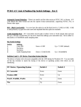
3-5 Serial Port COM1 Switch Settings..................................................................................3-25
3-6 Serial Port COM2 Switch Settings..................................................................................3-26
3-7 Parallel Port Switch Settings..........................................................................................3-26
3-8 Parallel Port Mode..........................................................................................................3-26
3-9 IDE Switch Configuration ...............................................................................................3-26
3-10 Floppy Drive Switch Settings..........................................................................................3-26
3-11 Reference Genlock Plug Jumper Settings .....................................................................3-29
3-12 Serial Digital I/O Plug Jumpers ......................................................................................3-34
3-13 Analog Composite Input Plug Jumpers..........................................................................3-37
3-14 Decoder Plug Jumpers...................................................................................................3-38
3-15 Analog Composite Output Plug Jumpers.......................................................................3-39
A-1 Serial Digital Video Input/Output.....................................................................................A-2
A-2 Analog Composite Video E-to-E (Direct) ........................................................................A-2
A-3 Analog Composite Video Output.....................................................................................A-3
A-4 Analog Composite Video E-to-E (Direct).........................................................................A-4
A-5 Program Input Genlock ...................................................................................................A-6
A-6 Analog Input/Output ........................................................................................................A-6
A-7 Component Analog Video Input ......................................................................................A-6
A-8 Component Analog Video Performance..........................................................................A-7
A-9 Format Voltage Level Definitions for CAVmtrxN Colorbar Matrix Test Clip ....................A-7
A-10 Format Voltage Level Definitions for CAVmtrxP Colorbar Matrix Test Clip.....................A-8
A-11 Reference Genlock..........................................................................................................A-9
A-12 Time Code.......................................................................................................................A-9
A-13 Analog Audio Mode.........................................................................................................A-9
A-14 Power Source..................................................................................................................A-9
A-15 Environmental Characteristics.......................................................................................A-10
A-16 Mechanical Characteristics ...........................................................................................A-10
A-17 Certification ...................................................................................................................A-11

PDR100 Installation ix
General Safety Summary
Review the following safety precautions to avoid injury and prevent
damage to this product or any products connected to it.
Only qualified personnel should perform service procedures.
While using this product, you may need to access other parts of the
system. Read the General Safety summary in other system manuals for
warnings and cautions related to operating the system.
Injury Precautions
Use Proper Power
Cord
To avoid fire hazard, use only the power cord specified for this product.
Ground the Product This product is grounded through the grounding conductor of the power
cord. To avoid electric shock, the grounding conductor must be
connected to earth ground. Before making connections to the input or
output terminals of the product, ensure that the product is properly
grounded.
Do Not Operate
Without Covers
To avoid electric shock or fire hazard, do not operate this product with
covers or panels removed.
Use Proper Fuse To avoid fire hazard, use only the fuse type and rating specified for this
product.
Do Not operate in
Wet/Damp
Conditions
To avoid electric shock, do not operate this product in wet or damp
conditions.
Do Not Operate in an
Explosive
Atmosphere
To avoid injury or fire hazard, do not operate this product in an explosive
atmosphere.
Avoid Exposed
Circuitry
To avoid injury, remove jewelry such as rings, watches, and other
metallic objects. Do not touch exposed connections and components
when power is present.
Product Damage Precautions
Use Proper Power
Source
Do not operate this product from a power source that applies more than
the voltage specified.
Provide Proper
Ventilation
To prevent product overheating, provide proper ventilation.
Do Not Operate With
Suspected Failures
If you suspect there is damage to this product, have it inspected by
qualified service personnel.

General Safety Summary
x PDR100 Installation
Safety Terms and Symbols
Terms in This
Manual
These terms may appear in this manual:
WARNING:Warning statements identify conditions or practices that can
result in personal injury or loss of life.
CAUTION: Caution statements identify conditions or practices that can
result in damage to the equipment or other property.
Terms on the
Product
These terms may appear on the product:
DANGER indicates a personal injury hazard immediately accessible as
one reads the marking.
WARNING indicates a personal injury hazard not immediately
accessible as you read the marking.
CAUTION indicates a hazard to property including the product.
Symbols on the
Product
The following symbols may appear on the product:
DANGER high voltage
Protective ground (earth) terminal
ATTENTION – refer to manual
Certifications and Compliances
Canadian Certified
Power Cords
Canadian approval includes the products and power cords appropriate for
use in the North America power network. All other power cords supplied
are approved for the country of use.
FCC Emission
Control
This equipment has been tested and found to comply with the limits for a
Class A digital device, pursuant to Part 15 of the FCC Rules. These limits
are designed to provide reasonable protection against harmful
interference when the equipment is operated in a commercial
environment. This equipment generates, uses, and can radiate radio
frequency energy and, if not installed and used in accordance with the
instruction manual, may cause harmful interference to radio
communications. Operation of this equipment in a residential area is
likely to cause harmful interference in which case the user will be
required to correct the interference at his own expense. Changes or
modifications not expressly approved by Tektronix can affect emission
compliance and could void the user’s authority to operate this equipment.
!
!
!
!
!
!

Certifications and Compliances
PDR100 Installation xi
Canadian EMC
Notice of
Compliance
This digital apparatus does not exceed the Class A limits for radio noise
emissions from digital apparatus set out in the Radio Interference
Regulations of the Canadian Department of Communications.
Le présent appareil numérique n’émet pas de bruits radioélectriques
dépassant les limites applicables aux appareils numériques de la classe A
préscrites dans le Règlement sur le brouillage radioélectrique édicté par
le ministère des Communications du Canada.
EN55022 Class A
Warning
For products that comply with Class A. In a domestic environment this
product may cause radio interference in which case the user may be
required to take adequate measures.

xii PDR100 Installation
Service Safety Summary
WARNING: These instructions are for use by qualified service
personnel only. To avoid personal injury, do not perform any servicing
unless you are qualified to do so. Refer to all safety summaries before
performing service.
Do Not Service
Alone
Do not perform internal service or adjustment of this product unless
another person capable of rendering first aid and resuscitation is present.
Disconnect Power To avoid electric shock, disconnect the main power by means of the
power cord. or, if provided, the power switch.
Use Care When
Servicing With
Power On
Dangerous voltages or currents may exist in this product. Disconnect
power, remove battery (if applicable), and disconnect test leads before
removing protective panels, soldering, or replacing components.
To avoid electric shock, do not touch exposed connections
!
!

PDR100 Installation 1-1
Chapter
1
Introduction
This manual is part of a set of manuals provided to support installation and operation
of the Tektronix PDR 100 Professional Disk Recorder. The set consists of the User
Manuals along with this Installation manual.
In addition to the PDR100 information, there are installation instructions for the
PDX103 Disk Expansion Unit, and the XLR100 Audio Bypass Unit. Each of these
has its own set of instructions but for ease of installation, mounting and cabling
information has been included in this manual.
Product Description
The PDR 100 is a disk-based video record and playback system yielding a quality
equal to beta machines using metal oxide tape. Aside from the obvious advantage of
not having to load tape, it occupies less rack space and is fully computer controlled.
Record/playback applications for the PDR 100 run on the Windows NT
TM
operating
system. The system’s total amount of program material storage depends on the
number of hard-disk drives and the video storage rate (number of bytes/field). With
the optional PDX103 Disk Expansion Unit and lowest video storage rate (50,000
bytes/field), it is possible to store up to nine hours of material.
The PDR 100 is mounted on rack slides for installation in either a standard or
“TELCO” rack. The unit is roughly the configuration of a large personal computer
(PC) with 16 Extended Industry Standard Architecture (EISA) slots, one ISA slot, up
to 32 Gbytes of disk storage, and a 32 by 32 CCIR 601 eight-bit routing switch. Three
control interfaces are supported: RS-232, RS-422, and keyboard/ mouse with VGA
output. The PDR 100 RS-422 interface has eight separate ports which require the
RS-422 Connector Panel (supplied with the PDR 100).
The system is controlled by an internal computer card with dedicated (system) hard
disk storage and a 3
1
/
2
-inch floppy disk drive. It can be addressed through any of the
three interfaces. A VGA circuit card supports an optional SVGA monitor for use with
the internal system controlling computer. The Microsoft Windows NT
TM
operating
software is loaded on the system hard disk.

Chapter 1 Introduction
1-2 PDR100 Installation
Operation Overview
Program video is input to the system in component serial digital, component analog,
or composite analog format, converted to parallel digital format, and routed to the
Disk Recorder circuit board by the on board video router. The parallel digital signal
is compressed (JPEG) and stored on the hard disk.
Upon recovery, the compressed parallel digital component video is decompressed and
routed to the output circuitry where it is converted back to serial digital or analog
format. The composite output undergoes an additional conversion back to either the
NTSC or PAL format. The composite output circuit board supports up to four
composite program outputs and a monitor channel. The monitor channel can have
time code burned in.
Each video channel can be supported by up to four channels of audio. A separate
audio circuit board is required for each four channels of audio input or output. The
audio signal is stored on a hard disk along with the video. For playback, the audio is
recovered from its storage location and output with the same video signal relationship
it had when recorded.
Control of the hard disks is accomplished by the Disk Recorder circuit boards, which
also provide the JPEG compression/decompression. The Master Disk Recorder can
control as few as 4 and as many as 12 hard disks. A Slave Disk Recorder can be added
to control between 4 and 12 additional hard disks. The total number of hard disks that
can be accommodated by a single PDR 100 (with PDX103 Disk Expansion unit) is
24.
The PDX103 is an optional Disk Expansion Unit containing its own power supply
and as many as 16 additional hard disks in a 7-inch (four rack units) high by 25.5-inch
deep, and 19-inch wide unit. The Disk Expansion Unit is delivered with either 8 hard
disks (2 banks of 4 to support 2 Disk Recorder boards in the PDR 100, a single bank
of 8 to support 1 Disk Recorder board), or with 16 hard disks to fully utilize the
capacity of 2 Disk Recorder boards.

Accessories
PDR100 Installation 1-3
Accessories
There are two types of accessories for the PDR100. Standard Accessories are those
items required to place the video disk recorder in service; they are shipped with the
VDR. Optional accessories are those available through Tektronix that will expand
VDR capabilities, simplify the installation, or aid in servicing.
Standard Accessories
The following items were included for shipment with the PDR 100:
• 1 Manual, Users (Tektronix part number 070-9042-XX)
• 1 Manual, Installation (Tektronix part number 070-9040-XX)
• Software Package
• 1 Windows NT instruction book (Tektronix part number 063-2284-XX)
• 1 Keyboard (Tektronix part number 119-4254-XX)
• 1 Mouse (Tektronix part number 119-4330-XX)
• 2 Packages (12 pieces) EMI Suppression Gaskets for BNC Connectors (Tektronix
part number 016-1448-XX)
• 1 Cable Assembly, Power (161-0216-00 for US and Japan; 161-0066-09 for
Europe; 161-0066-10 for the United Kingdom; or 161-0066-11 for Australia)
• 1 SCSI Terminator (011-0166-00)
• 1 RS-422 Control panel, with interconnecting cable (039-0028-XX)
• 1 Set of rack-mounting slides
Optional Accessories
The following items are available from Tektronix, Inc. Contact your nearest field
office or distributor for more information.
• SVGA Monitor
• Service Manual (Tektronix part number 070-9041-XX)
• XLR100 Audio Bypass and Breakout Unit
• PDX103 Disk Drive Expansion Unit
• Additional Hard Disk Drives for either PDR100-Series or PDX103
•
Eight-connector DB25-XLR breakout cable for audio or longitudinal time code I/O
(Tektronix part number 174-3249-XX)
• Eight-connector breakout cable, with DB25 connector and tinned leads (Tektronix
part number 174-3481-XX)

Chapter 1 Introduction
1-4 PDR100 Installation

PDR100 Installation 2-1
Chapter
2
Configuration
The PDR100 Mother board with its connectors for the circuit boards allows the
PDR100 to be configured in a number of ways. Any configuration of the PDR100
consists of circuit boards that are required in all configurations and circuit boards
specific to a particular configuration.
On the Mother board, the connectors are arranged into the EISA bus and Video Router
as shown in Figure 2-1. All of the circuit boards plug into the EISA bus. (Slot J2,
which is on the EISA bus, is limited to ISA only.) A number of the circuit boards, such
as the Master or Slave Disk Recorder and the Input/Output (I/O) boards, require
connection to both the EISA bus and the Video Router, which is provided by slots
J5-J16.
Figure 2-1. Circuit Board Slot Nomenclature
J1 J2 J5
J105
J17
J16J14
J9
ISA
Only
EISA Bus
Video Router
J116J109 J112
9040-2

Chapter 2 Configuration
2-2 PDR100 Installation
Configuration Guidelines
The information given here is to help install circuit boards in configurations that differ
from factory configurations. This information can be useful when adding a new
circuit board to the PDR100 and you need to move boards around to make room.
Some of the circuit boards must be installed in specific locations, others are installed
in locations that are dictated by the configuration.
Circuit Board Installation Rules
In order to ensure correct operation of the PDR100, it is necessary to follow some
specific rules involving the installation of the various circuit boards.
• Processor and VGA boards must be installed in Mother board slots J1 and J2
respectively.
• Slots J5 through J16 have access to both the EISA bus and the Video Router;
however, the number of router connections accessible from specific slots varies,
making it necessary to arbitrarily assign some configuration-specific boards to
designated slots.
• Disk Recorder circuit boards must be in Mother board slots J14 (Master) and J15
(Slave).
• Slot J17 on the Mother board is EISA only and is dedicated to the RS-422 board.
• The Reference Genlock circuit board must be installed in Mother board slot J16.
• Analog Composite Output circuit boards (for NTSC or PAL) can only be installed
in Mother board slots J11 or J12.
• Audio circuit boards need to be close enough to their respective input or output
boards to allow clock cabling. In most cases, the audio board will be adjacent to
the input board and no more than two slots away from the output board.
• Serial I/O boards cannot be installed adjacent to Analog Composite Output boards.

Circuit Boards Required for All Configurations
PDR100 Installation 2-3
Circuit Boards Required for All Configurations
The following circuit boards are required in every PDR100:
• Processor
• VGA-I/O
• Reference Genlock
• Master Disk Recorder
• RS-422 Interface
Processor
The Processor is always installed in slot J1. It communicates with the outside world
through the RS-422 Interface circuit board (that is installed in J17), RS-232 interface,
VGA, mouse keyboard combination, and if installed, a Local Area Network (LAN)
circuit board.
VGA-I/O
The VGA-I/O board is always installed in slot J2 next to the Processor board. In
addition to the video interface for the monitor, this board provides internal
connections to the PDR100’s RS-232 Serial port, the system hard disk drive, and the
floppy disk drive. There is also a parallel port, the IDE interface for the system hard
disk, and the floppy disk driver.
Reference Genlock
Slot J16 is assigned to the Reference Genlock circuit board. It requires both EISA bus
and Video Router connections. Like its neighbor the RS-422 Interface circuit board,
it is required for all configurations.
Master Disk Recorder
Each Disk Recorder circuit board requires a set of four or eight hard disk drives. This
can be as many as 12 hard disk drives per Disk Recorder, when the PDX103 is also
used. The Master Disk Recorder circuit board is always located in slot J14. It controls
4, 8, or 12 hard disk drives, depending on the number of hard disk drives installed and
whether the PDX103 is in use.

Chapter 2 Configuration
2-4 PDR100 Installation
Circuit Boards that Support Configurations
Some of the circuit boards can be loaded into almost any of the slots, while others
must go into specified locations. The slots that are available for configuration-specific
circuit boards are J3 through J13. See Figure 2-2.
J14 through J17 are also dedicated slots, used for the Disk Recorders, Reference
Genlock, and RS422A Interface circuit boards.
Slave Disk Recorder
When the PDR100 is configured for four channel operation, a Slave Disk Recorder
circuit board is required. This circuit board is always located in slot J15.
Analog Composite Input
The Analog Composite Video Input is a two circuit board set requiring two EISA/
Video Router slots (between J5 and J13.) One slot is occupied by the Decoder circuit
board, while the second slot has the one video-channel Input circuit board.
Figure 2-2. Required Circuit Boards for All Configurations
J116
J1 J2 J5
J105
J17
J16J14
J9
J109 J112
Processor,
Master Disc
Controller
Reference
Genlock
VGA, & RS-422 I/O
EISA Bus
Video Router
9040-3
/