Vizio VMA13-32 Installation Instructions Manual
- Category
- Wall & ceiling mounts accessories
- Type
- Installation Instructions Manual
This manual is also suitable for
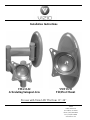
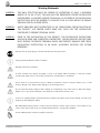
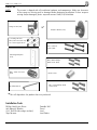
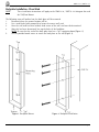
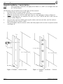
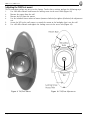
Vizio VMA13-32 is an articulating swing-out arm and tilt-pivot mount for Vizio LCD TVs between 13" and 32". It includes all necessary hardware like 1/4” wedge anchors, #14x2” wood screws, M4x10mm Phillips head screws, M6x35mm set screw, M3 Allen wrench, 14mm socket, as well as M4x16mm Phillips head screws. It comes with safety warnings and instructions for backplate installation on wood studs or concrete surfaces, mount installation, monitor installation, as well as detailed adjustment instructions for both swingout arm and tilt/pivot mount.
Vizio VMA13-32 is an articulating swing-out arm and tilt-pivot mount for Vizio LCD TVs between 13" and 32". It includes all necessary hardware like 1/4” wedge anchors, #14x2” wood screws, M4x10mm Phillips head screws, M6x35mm set screw, M3 Allen wrench, 14mm socket, as well as M4x16mm Phillips head screws. It comes with safety warnings and instructions for backplate installation on wood studs or concrete surfaces, mount installation, monitor installation, as well as detailed adjustment instructions for both swingout arm and tilt/pivot mount.


-
 1
1
-
 2
2
-
 3
3
-
 4
4
-
 5
5
-
 6
6
-
 7
7
-
 8
8
-
 9
9
-
 10
10
-
 11
11
-
 12
12


Vizio VMA13-32 Installation Instructions Manual
- Category
- Wall & ceiling mounts accessories
- Type
- Installation Instructions Manual
- This manual is also suitable for
Vizio VMA13-32 is an articulating swing-out arm and tilt-pivot mount for Vizio LCD TVs between 13" and 32". It includes all necessary hardware like 1/4” wedge anchors, #14x2” wood screws, M4x10mm Phillips head screws, M6x35mm set screw, M3 Allen wrench, 14mm socket, as well as M4x16mm Phillips head screws. It comes with safety warnings and instructions for backplate installation on wood studs or concrete surfaces, mount installation, monitor installation, as well as detailed adjustment instructions for both swingout arm and tilt/pivot mount.
Ask a question and I''ll find the answer in the document
Finding information in a document is now easier with AI
Related papers
-
Vizio M190MV User manual
-
Vizio VX240M - 24" LCD TV Quick start guide
-
Vizio E421VA User manual
-
-
Vizio M470VT User manual
-
-
Vizio M190VA User manual
-
-
-
Other documents
-
Home Decorators Collection HDCCL24G Installation guide
-
Samsung TWMB-1900 Setup Manual
-
Allied Brass 420-GYM Installation guide
-
-
-
Unbranded 9085628 Installation guide
-
Premier Mounts TV Mount XUF-1330L User manual
-
-
Vanco WMT2337 Mounting instructions
-
Premier MMT Installation guide