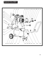
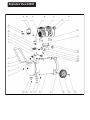
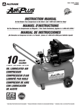
SIP 04381 is a portable air compressor with a 24L or 50L air receiver, designed for a variety of tasks such as inflating tires, powering air tools, and painting. It features an electric motor with thermal overload protection, an air pressure regulator with gauges, a quick coupler for easy connection of air tools, and a pressure relief safety valve. The compressor is easy to assemble and operate, and it comes with a one-year warranty.
SIP 04381 is a portable air compressor with a 24L or 50L air receiver, designed for a variety of tasks such as inflating tires, powering air tools, and painting. It features an electric motor with thermal overload protection, an air pressure regulator with gauges, a quick coupler for easy connection of air tools, and a pressure relief safety valve. The compressor is easy to assemble and operate, and it comes with a one-year warranty.


-
 1
1
-
 2
2
-
 3
3
-
 4
4
-
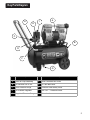 5
5
-
 6
6
-
 7
7
-
 8
8
-
 9
9
-
 10
10
-
 11
11
-
 12
12
-
 13
13
-
 14
14
-
 15
15
-
 16
16
-
 17
17
-
 18
18


SIP 04381 is a portable air compressor with a 24L or 50L air receiver, designed for a variety of tasks such as inflating tires, powering air tools, and painting. It features an electric motor with thermal overload protection, an air pressure regulator with gauges, a quick coupler for easy connection of air tools, and a pressure relief safety valve. The compressor is easy to assemble and operate, and it comes with a one-year warranty.
Ask a question and I''ll find the answer in the document
Finding information in a document is now easier with AI
Other documents
-
SIP INDUSTRIAL QTA24-10 Air Oil Less Air Compressors User manual
-
Ranger Products R2513H Operating instructions
-
NORTHSTAR PORTABLE ELECTRIC AIR COMPRESSOR Owner's manual
-
SIP INDUSTRIAL 036333 User manual
-
 AllTrade #540025 User manual
-
Aavix A12103 User guide
-
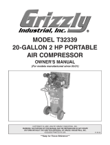 Grizzly PRO T32339 Owner's manual
-
Yetter 2984-050 Strip Freshener CC (Cab Controlled) Owner's manual
-
 Grizzly PRO T32337 Owner's manual
-
Central Pneumatic Item 61489 Owner's manual


