IMI Hydronic Engineering TA Fast-Fit 4 User manual

Type
User manual

IMI Hydronic Engineering TA Fast-Fit 4 is a prefabricated solution for small terminal units, providing easy installation and maintenance of heating and cooling systems. It features a compact design with integrated components like shut-off valves, drain valves, strainers, and bypasses, reducing the need for additional fittings and saving time during installation. The TA Fast-Fit 4 allows for forward and back flushing of the distribution system, ensuring efficient cleaning and maintenance.

IMI Hydronic Engineering TA Fast-Fit 4 is a prefabricated solution for small terminal units, providing easy installation and maintenance of heating and cooling systems. It features a compact design with integrated components like shut-off valves, drain valves, strainers, and bypasses, reducing the need for additional fittings and saving time during installation. The TA Fast-Fit 4 allows for forward and back flushing of the distribution system, ensuring efficient cleaning and maintenance.

1
9696-32-800-480 UK
12.2022
TA Fast-Fit 4
2
www.imi-hydronic.com
TA Fast-Fit 4
Prefabricated solutions
For small terminal units
TA-Modulator/TA-COMPACT-P STAV
3
TA-Modulator
TA-COMPACT-P
STAV
Female threads
Shut-off valve
Female threads
Strainer (optional)
By-pass
p
T
Drain valve
H
q
T
NOTE!
It is not allowed to hold the
TA Fast-Fit 4 assembly, during
installation, on other places then
indicated by the wrenches in the
illustration.
Max. torque 50 Nm (36.9 lbf.ft.)
NOTE! Assembly example, product components may vary.
DN 15-20: 119 / 128 / 145 mm *
(1/2’’ - 3/4’’: 4.68’’ / 5.04’’ / 5.71’’) *
DN 25: 130 / 139 / 156 mm *
(1’’: 5.12’’ / 5.47’’ / 6.14’’) *
DN 32: 133 / 142 / 159 mm *
(1 1/4’’: 5.24’’ / 5.59’’/ 6.26’’) *
~15 mm (~0.59’’)
DN 10-20: 107 mm
(3/8’’ - 3/4’’: 4.21’’)
DN 25-32: 113 mm
(1’’ - 1 1/4’’: 4.45’’)
~15 mm (~0.59’’)
IP54
IP54
EMO T / EMO TM TA-Slider 160
*) Depending on version
4
TA-Modulator
(TA-STR optional)
3
4
2
1
TA-Modulator
(TA-STR optional)
3
4
12
TA-Modulator
(TA-STR optional)
3
4
12
TA-Modulator
(TA-STR optional)
3
4
12
Normal operation Back ushing
Flushing the distribution system Forward ushing
1. Open
2. Closed
3. Open
4. Open
1. Closed
2. Open
3. Open
4. Open
1. Closed
2. Closed
3. Open
4. Closed
1. Open
2. Open
3. Closed
4. Open
Open   Closed  Flushingthediributionsyem
5
TA-Modulator / TA-COMPACT-P
10.0
1“X” 1Example!
“5”
q
123
45
6
DH
12
“X”
3
5 mm
~1
456
8Example!
7
9
7
Fixed orice double regulating valve
Installation
Toensureowmeasurementaccuracyitis
essential that
1 the valve must be installed in a straight run
of pipe of the same nominal size, with the
 owarrowonthevalvebodypointinginthe
 directionofow.
2 the piping in the inlet side is straight and has
a minimum length according to Fig. 1.
3 after cutting the pipe, the end must be
 deburredbeforettingittothevalve.
N.B. If using pipes smaller than valve size
(also when using KOMBI) – contact
IMI Hydronic Engineering.
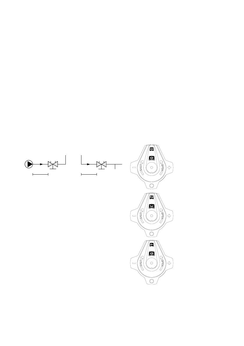
Installation layout
N.B. Toensureowmeasurementaccuracy
it is essential that the piping in the inlet side is
straight and has a minimum length according
to Fig. 1.
Pipe cutting
After cutting the pipe, the end must be
deburredbeforettingittothevalve.Failureto
carry out this procedure may lead to errors in
owmeasurementaccuracy.
5D10D
STAV STAV
Fig 1. D = Valve DN
Setting
Flow regulation is achieved by adjusting the
valvesettinguntiltherequiredowrateis
obtained. The handwheel will indicate the valve
setting.
For maximum limit of the valve, use a 3 mm
Allen key, turn the inner spindle clockwise to its
end position.
Valve setting indicator
The valves operate from closed to fully open
with 4 complete turns of the handwheel.
The handwheel indicates the valve setting
by means of digits appearing in outer (black)
and inner (red) windows. The digit in the outer
window indicates the number of full turns. The
digit in the inner window indicates tenths of a
turn.
Valve closed
Opened 2.3 turns
Fully open valve
STAV
8
www.imi-hydronic.com
We reserve the right to introduce technical alterations without prior notice.
  • Page 1 1
  • Page 2 2
  • Page 3 3
  • Page 4 4
  • Page 5 5
  • Page 6 6
  • Page 7 7
  • Page 8 8

IMI Hydronic Engineering TA Fast-Fit 4 User manual

Type
User manual

IMI Hydronic Engineering TA Fast-Fit 4 is a prefabricated solution for small terminal units, providing easy installation and maintenance of heating and cooling systems. It features a compact design with integrated components like shut-off valves, drain valves, strainers, and bypasses, reducing the need for additional fittings and saving time during installation. The TA Fast-Fit 4 allows for forward and back flushing of the distribution system, ensuring efficient cleaning and maintenance.

Ask a question and I''ll find the answer in the document

Finding information in a document is now easier with AI