Page is loading ...

Agility™ Water-cooled Chiller
Filterless Motor Compressor Retrofit
KIT19897
Installation Instructions
December 2022
SAFETY WARNING
Only qualified personnel should install and service the equipment. The installation, starting up, and servicing of
heating, ventilating, and air-conditioning equipment can be hazardous and requires specific knowledge and training.
Improperly installed, adjusted or altered equipment by an unqualified person could result in death or serious injury.
When working on the equipment, observe all precautions in the literature and on the tags, stickers, and labels that are
attached to the equipment.
PART-SVN255A-EN
X39641445001

©2022 Trane PART-SVN255A-EN
Introduction
Read this manual thoroughly before operating or servicing this
unit.
Warnings, Cautions, and Notices
Safety advisories appear throughout this manual as required.
Your personal safety and the proper operation of this machine
depend upon the strict observance of these precautions.
Important Environmental Concerns
Scientific research has shown that certain man-made
chemicals can affect the earth’s naturally occurring
stratospheric ozone layer when released to the atmosphere. In
particular, several of the identified chemicals that may affect
the ozone layer are refrigerants that contain Chlorine, Fluorine
and Carbon (CFCs) and those containing Hydrogen, Chlorine,
Fluorine and Carbon (HCFCs). Not all refrigerants containing
these compounds have the same potential impact to the
environment. Trane advocates the responsible handling of all
refrigerants-including industry replacements for CFCs and
HCFCs such as saturated or unsaturated HFCs and HCFCs.
Important Responsible Refrigerant
Practices
Trane believes that responsible refrigerant practices are
important to the environment, our customers, and the air
conditioning industry. All technicians who handle refrigerants
must be certified according to local rules. For the USA, the
Federal Clean Air Act (Section 608) sets forth the requirements
for handling, reclaiming, recovering and recycling of certain
refrigerants and the equipment that is used in these service
procedures. In addition, some states or municipalities may
have additional requirements that must also be adhered to for
responsible management of refrigerants. Know the applicable
laws and follow them.
The three types of advisories are defined as follows:
WARNING Indicates a potentially hazardous
situation which, if not avoided, could
result in death or serious injury.
CAUTIONsIndicates a potentially hazardous
situation which, if not avoided, could
result in minor or moderate injury. It could
also be used to alert against unsafe
practices.
NOTICE Indicates a situation that could result in
equipment or property-damage only
accidents.
WARNING
Proper Field Wiring and Grounding
Required!
Failure to follow code could result in death or serious
injury. All field wiring MUST be performed by qualified
personnel. Improperly installed and grounded field
wiring poses FIRE and ELECTROCUTION hazards. To
avoid these hazards, you MUST follow requirements for
field wiring installation and grounding as described in
NEC and your local/state/national electrical codes.
WARNING
Personal Protective Equipment (PPE)
Required!
Failure to wear proper PPE for the job being undertaken
could result in death or serious injury. Technicians, in
order to protect themselves from potential electrical,
mechanical, and chemical hazards, MUST follow
precautions in this manual and on the tags, stickers,
and labels, as well as the instructions below:
• Before installing/servicing this unit, technicians
MUST put on all PPE required for the work being
undertaken (Examples; cut resistant gloves/sleeves,
butyl gloves, safety glasses, hard hat/bump cap, fall
protection, electrical PPE and arc flash clothing).
ALWAYS refer to appropriate Safety Data Sheets
(SDS) and OSHA guidelines for proper PPE.
• When working with or around hazardous chemicals,
ALWAYS refer to the appropriate SDS and OSHA/GHS
(Global Harmonized System of Classification and
Labeling of Chemicals) guidelines for information on
allowable personal exposure levels, proper
respiratory protection and handling instructions.
• If there is a risk of energized electrical contact, arc, or
flash, technicians MUST put on all PPE in accordance
with OSHA, NFPA 70E, or other country-specific
requirements for arc flash protection, PRIOR to
servicing the unit. NEVER PERFORM ANY
SWITCHING, DISCONNECTING, OR VOLTAGE
TESTING WITHOUT PROPER ELECTRICAL PPE AND
ARC FLASH CLOTHING. ENSURE ELECTRICAL
METERS AND EQUIPMENT ARE PROPERLY RATED
FOR INTENDED VOLTAGE.

Introduction
PART-SVN255A-EN 3
Copyright
This document and the information in it are the property of
Trane, and may not be used or reproduced in whole or in part
without written permission. Trane reserves the right to revise
this publication at any time, and to make changes to its content
without obligation to notify any person of such revision or
change.
Trademarks
All trademarks referenced in this document are the trademarks
of their respective owners.
WARNING
Follow EHS Policies!
Failure to follow instructions below could result in
death or serious injury.
• All Trane personnel must follow the company’s
Environmental, Health and Safety (EHS) policies
when performing work such as hot work, electrical,
fall protection, lockout/tagout, refrigerant handling,
etc. Where local regulations are more stringent than
these policies, those regulations supersede these
policies.
• Non-Trane personnel should always follow local
regulations.

4 PART-SVN255A-EN
Table of Contents
General Information . . . . . . . . . . . . . . . . . . . . . . . 5
Purpose . . . . . . . . . . . . . . . . . . . . . . . . . . . . . . 5
Related Literature . . . . . . . . . . . . . . . . . . . . . . 5
Sample Nameplate . . . . . . . . . . . . . . . . . . . . . 5
Parts List . . . . . . . . . . . . . . . . . . . . . . . . . . . . . . 5
Tools Required . . . . . . . . . . . . . . . . . . . . . . . . . 6
Parts not Included . . . . . . . . . . . . . . . . . . . . . . 6
Installation . . . . . . . . . . . . . . . . . . . . . . . . . . . . . . . 7
Shutdown Power . . . . . . . . . . . . . . . . . . . . . . . 7
Major Component Description . . . . . . . . . . . . 7
Trane Unit Controls . . . . . . . . . . . . . . . . . . . . . 8
UC800/Symbio™ 800 . . . . . . . . . . . . . . . . . 8
Compressor Removal . . . . . . . . . . . . . . . . . . . 8
Output Filter Panel Removal . . . . . . . . . . . . . . 8
Drain Glycol Tank . . . . . . . . . . . . . . . . . . . . . . 9
Component Weights . . . . . . . . . . . . . . . . . . . 11
Rigging and Lifting . . . . . . . . . . . . . . . . . . . . . 11
Unit Lifting Points – Preferred Lifting
Method . . . . . . . . . . . . . . . . . . . . . . . . . . . . 12
Unit Lifting Points – Alternative Lifting
Method . . . . . . . . . . . . . . . . . . . . . . . . . . . . 12
Secure Filter . . . . . . . . . . . . . . . . . . . . . . . . . . 12
Remove Filter . . . . . . . . . . . . . . . . . . . . . . . . . 12
Glycol Cooling Line Installation . . . . . . . . . . . 13
Transition Box Installation . . . . . . . . . . . . . . . 14
Compressor Installation . . . . . . . . . . . . . . . . . 15

PART-SVN255A-EN 5
General Information
Chillers with the following configuration should be retrofit with
a new compressor:
• Agility Model HDWA
• 300 or 400 ton units
• Built prior to February 2023
• Design sequence AD or earlier
Purpose
The compressor used for 300 and 400T Agility chillers built
prior to February 2023 has been discontinued in production.
The replacement compressor does not require the output filter.
This retrofit allows the use of the newly offered compressor,
and removal of output filter for older units.
Related Literature
•Installation, Operation, and Maintenance, Agility™
Water-cooled Chillers with Symbio™ Controls
(HDWA-SVX002*-EN)
•Service Guide, Agility™ Water-cooled Chillers with
Symbio™ Controls (HDWA-SVG002*-EN)
•Installation Guide, Agility™ Water-cooled Chillers with
Symbio™ Controls Disassembly and Reassembly
(HDWA-SVN003*-EN)
•Programming Guide, Tracer® TU Service Tool for use with
Water-cooled Agility™ Chillers with Symbio™ Controls
(HDWA-SVP002*-EN)
•Service Manual, TR200 New D-Frame, 110-400 kW
(BAS-SVM01*-EN)
•Programming Guide, Danfoss TR200 (BAS-SVP04*-EN)
•HUB Solution, HDWA Agility™ Drive Configuration
Instructions (MCT10 Software Tool)
•Installation Instructions, Symbio™ 800 Control Upgrade
Kit for UC800 Adaptiview™ Display (CDUB-SVN002*-EN)
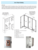
Sample Nameplate
Parts List
Figure 1. Sample nameplate
Table 1. Parts list for KIT19897
Manufacturing
Part Number Part Description
453742500001 ASSEMBLY; TRANSITION ENCLOSURE
X13491386030 TERMINAL BLOCK; 2P
453742530001 WIRE KIT; TRANSITION HARNESS, 313MCM
X19150693001 RING TERMINAL; 50
X19210282010 WIRE TIE
X20600036020 EDGE MOLDING
X45050656010 HOSE; DRIVE COOLING, 3/4 INCH I.D. - 200 P.S.I.
X32030305030 HOSE CLAMP
453722250001 ASSEMBLY; WIRE TRAY
X19051622020 WIRE HARNESS; 1-2 BRANCHING 1000 MM
CNT09384 DANFOSS TR200 MARKII CONTROL CARD
Table 2. Compressor part numbers
Size (tons) Part Number
300 COM13897
400 COM13896

General Information
6 PART-SVN255A-EN
Tools Required
• 1/8 in. and 3/8 in. wide flat head screwdrivers
• Flat head screwdriver
• Phillips screwdriver
• Torque wrench
• Socket set
• Breaker bar
• Rigging and lifting equipment
• Spreader bar
• Wrenches
• T20 torx head driver
• Danfoss MCT10 service tool
• USB cable Type A to Type B
• Wiring Tool
Parts not Included
• Glycol
•Wire ties
• Symbio™ upgrade kit (if required)

PART-SVN255A-EN 7
Installation
Shutdown Power
1. Using lockout/tagout safety procedures, shutdown main
power to the chiller.
2. Open all starter and control panel disconnect switches and
secure them in the open position.
3. Confirm the power is off to the chiller control panel.
Major Component Description
WARNING
Hazardous Voltage w/Capacitors!
Failure to disconnect power and discharge capacitors
before servicing could result in death or serious injury.
Disconnect all electric power, including remote
disconnects and discharge all motor start/run
capacitors before servicing. Follow proper lockout/
tagout procedures to ensure the power cannot be
inadvertently energized. For variable frequency drives
or other energy storing components provided by Trane
or others, refer to the appropriate manufacturer’s
literature for allowable waiting periods for discharge of
capacitors. Verify with a CAT III or IV voltmeter rated per
NFPA 70E that all capacitors have discharged.
WARNING
Refrigerant under High Pressure!
Failure to follow instructions below could result in an
explosion which could result in death or serious injury
or equipment damage.
System contains refrigerant under high pressure.
Recover refrigerant to relieve pressure before opening
the system. See unit nameplate for refrigerant type. Do
not use non-approved refrigerants, refrigerant
substitutes, or refrigerant additives.
WARNING
Hazardous Voltage!
Failure to disconnect power before servicing could
result in death or serious injury.
Disconnect all electric power, including remote
disconnects before servicing. Follow proper lockout/
tagout procedures to ensure the power can not be
inadvertently energized. Verify that no power is present
with a voltmeter.
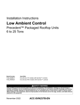
Figure 2. Affected chiller components
Drive
Wire Trays
Drive Cooling/
Glycol Loop
Motor Leads and
Wire Trays
Compressor
Output Filter

Installation
8 PART-SVN255A-EN
Trane Unit Controls
UC800/Symbio™ 800
If the existing chiller has UC800 controls, an upgrade to
Symbio™ 800 is required as part of the compressor
replacement. Follow the instructions in Installation
Instructions, Symbio™ 800 Control Upgrade Kit for UC800
Adaptiview™ Display (CDUB-SVN002*-EN).
Danfoss TR200 Drive Control Board
1. Determine the control board version using the figures
below.
•Markl: USB connector has a black element.
•MarkII: USB has a white element.
2. MarkII control board does not need to be replaced.
3. If control board is MarkI, replace with a MarkII version as
follows:
a. Copy the configuration from the drive to your laptop.
See HUB Solution, HDWA Agility Drive Configuration
Instructions (MCT10 Software Tool).
b. Remove the MarkI control board and install the MarkII
control board. See Service Manual, TR200 New D-
Frame, 110-400 kW (BAS-SVM01*-EN), section 7.3.2
for replacement procedure.
c. Load the drive configuration from your laptop to the
connected drive. See HUB Solution, HDWA Agility
Drive Configuration Instructions (MCT10 Software
Tool).
Compressor Removal
Note: The existing compressor must be removed before filter
removal. Glycol piping and transition box must be
reinstalled prior to the installation of the replacement
compressor.
Remove compressor per instructions found in Service Guide,
Agility™ Water-cooled Chillers with Symbio™ Controls
(HDWA-SVG002*-EN).
Output Filter Panel Removal
Follow the procedure below for instructions for removing the
existing output filter panel.
Figure 3. Retrofitted chiller components
Figure 4. MKI card
Figure 5. MKII card

Installation
PART-SVN255A-EN 9
Drain Glycol Tank
1. Remove glycol system drain plug.
2. Open drain valve to drain the glycol tank.
3. Remove bottom hose of heat exchanger and drain.
4. Remove top hose of heat exchanger and drain.
Drain Plug
Drain Valve

Installation
10 PART-SVN255A-EN
5. Remove hose connection cover.
6. Disconnect hose fittings.
7. Remove filter bolt covers.
8. Disconnect filter output wires.
Hose Cover

Installation
PART-SVN255A-EN 11
9. Remove vertical wire cover box.
10. Remove horizontal wire cover box.
Component Weights
Rigging and Lifting
Table 3. Component weights
Component Weight (lb)
Existing filter 250
New buss bar enclosure 72
WARNING
Heavy Objects!
Failure to follow instructions below or properly lift unit
could result in unit dropping and possibly crushing
operator/technician which could result in death or
serious injury, and equipment or property-only damage.
Ensure that all the lifting equipment used is properly
rated for the weight of the unit being lifted. Each of the
cables (chains or slings), hooks, and shackles used to
lift the unit must be capable of supporting the entire
weight of the unit. Lifting cables (chains or slings) may
not be of the same length. Adjust as necessary for even
unit lift.

Installation
12 PART-SVN255A-EN
Unit Lifting Points – Preferred Lifting
Method
The preferred method for lifting a filter unit to position it for
installation is to use an identical individual hoisting device at
each lift point.
Unit Lifting Points – Alternative Lifting
Method
If it is only possible to use a single hoisting device to lift a filter
unit to position it for installation, a spreader bar should be used
to allow adjusting the rigging as necessary to balance the unit
around its center-of-gravity to ensure full control of the unit
during lifting.
Secure Filter
1. Install lifting eyes on top of the filter.
2. Secure filter with proper lifting device.
Remove Filter
1. Remove filter bolts from the drive.
WARNING
Improper Unit Lift!
Failure to properly lift unit in a LEVEL position could
result in unit dropping and possibly crushing operator/
technician which could result in death or serious injury,
and equipment or property-only damage.
Test lift unit approximately 24 inches (61 cm) to verify
proper center of gravity lift point. To avoid dropping of
unit, reposition lifting point if unit is not level.
Figure 6. Preferred lifting method using two identical
individual hoists
Figure 7. Alternative lifting method using a single
hoist and spreader bar

Installation
PART-SVN255A-EN 13
2. Lift filter away from unit.
a. Headroom required is: 13 3/8 inches (339 mm).
b. If headroom clearance is not sufficient, remove
economizer flange and remove the economizer tube.
Replace provided economizer O-ring during
reassembly.
Glycol Cooling Line Installation
Install glycol cooling lines as described for your specific chiller
application.
1. Install the kit supplied hoses onto existing barbed fittings
and secure with hose clamps.
2. Refill glycol system using amounts listed in table below and
Service Guide, Agility™ Water-cooled Chillers with
Symbio™ Controls (HDWA-SVG002*-EN):
Figure 8. Glycol cooling lines
Figure 9. Glycol cooling line installation (single drive)
Figure 10. Glycol cooling line installation (dual drive)
Drive Glycol amount (gal)
Single 0.9
Double 1.1

Installation
14 PART-SVN255A-EN
Transition Box Installation
1. Using proper lifting procedures, lift transition box into place
in the location of the previous filter.
2. Bolt transition box in place.
3. Route the drive wires to the transition assembly and install
horizontal wire cover box.
4. Install vertical wire cover box.
5. Fasten the wire lugs to the proper bus bars. Torque
fasteners 22 to 26 ft-lb.

Installation
PART-SVN255A-EN 15
6. Install rubber edge molding onto the tie down bracket and
onto the inside flange of the transition cover.
7. Secure the transition box cover.
Compressor Installation
1. Complete the compressor installation per Service Guide,
Agility™ Water-cooled Chillers with Symbio™ Controls
(HDWA-SVG002*-EN).
2. Position power wires onto motor terminals and tighten wire
ties so the wires do not put stress on the terminals.
3. Trim black and black/white leads on the potential
transformer (4T1). Crimp on 1/2 inch diameter ring
terminals and install on motor terminals as follows:
•Black/white: T1 terminal
•Black: T2 terminal
4. Torque nuts to 22 to 26 ft-lb (29.8 to 35.2 Nm).
5. Replace covers.

©2022 Trane
Trane has a policy of continuous product and product data improvement and reserves the right to change design and specifications without notice. We
are committed to using environmentally conscious print practices.
Trane - by Trane Technologies (NYSE: TT), a global climate innovator - creates comfortable, energy efficient
indoor environments for commercial and residential applications. For more information, please visit trane.com
or tranetechnologies.com.
PART-SVN255A-EN 03 Dec 2022
(NEW)
/