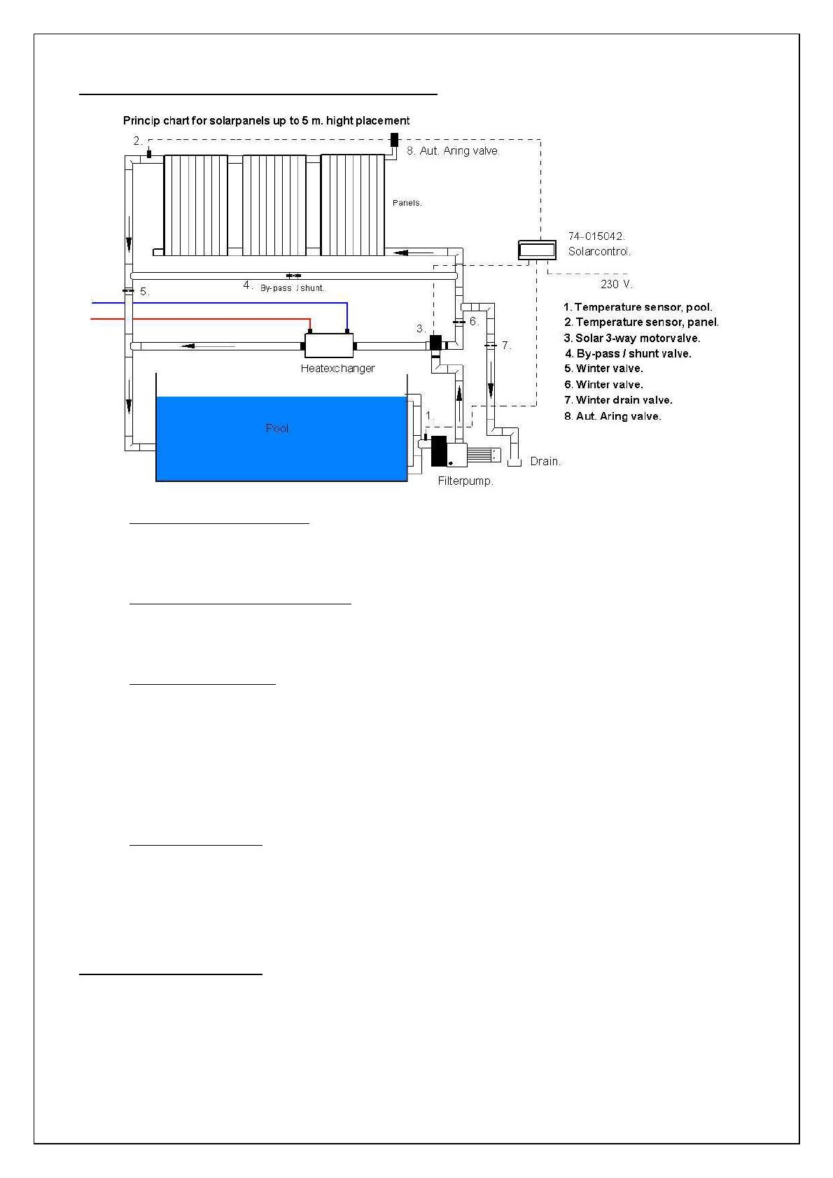
2. Installation diagram for solar panel and control unit
1. The pool temperature sensor should be installed on the suction side of the filter pump or immediately
after the filter pump. The sensor must be protected against direct sunlight and draughts/air streams
from pump(s) which may adversely affect the ability of the sensor to measure actual pool
temperature. Insulate the sensor if necessary.
2. The solar panel temperature sensor must be installed on the solar panel outlet, preferably on the
rear of the panel in order to prevent sunlight from adversely affecting the ability of the sensor to
measure actual panel temperature. Insulate the sensor if necessary. If it is necessary to extend the
sensor cable, a 2 x 1.5 mm² cable must be used as minimum.
3. Solar 3-way motorvalve (type 74-120463) must be installed as illustrated. The valve is T-shaped.
Water from the filter pump must be led in from below. Water to the solar panel should be led out to
the right while water to the pool is led out to the left. If necessary, the solar panel and pool outlets
may be exchanged. The limit switch function of the control unit can also be exchanged by
exchanging the wires from NO and NC. The outlets can thus be used as required. See fig. 2.
4. Note! To allow the measurement of panel temperature, a small flow will be maintained even when
the valve has shut off the water supply to the solar panel. Such temperature data is required by the
controls.
5. A shunt/bypass valve must be installed if the flow (in m³) through the filter pump is greater than the
total capacity of the solar panel. The shunt/bypass valve can also be used to trim the system
depending on season.
6. The valve no. 7 must be opened when shutting down the system for the winter. Valve no. 5 & 6 must
be closed. If the panels are inclined, the air-release valve (type 74-100103) allows the water
contained in them to be drained.
3. Installing the control unit
• The control unit must be installed in an easily accessible dry location.
• The control unit should be connected parallel to the pool filter pump (230 V).
• Control output: 24 vac. NC – NO – N. To motor-driven valve. Max. 5 VA.
• Control output: 230 vac. NC – NO – N. To 230 v motor.driven valve. Max 10A.
• Control output: 230 vac. NO – N. To 230 v solar pump. Max. 10A.
• Sensor cables must not be positioned alongside 230/400 V cables as the resulting induction will
cause deviation in sensor ohm values.