Hinkley 903680FGT-LDD User manual

Category
Household fans
Type
User manual

This manual is also suitable for

CEILING FAN INSTRUCTION MANUAL
DC
DC MOTOR LEDDAMP
INDOOR/OUTDOOR LED FAN
80" SCULPT
SO WE’RE HERE IF YOU HAVE A QUESTION, NEED SOME
HELP OR WANT TO CHAT ABOUT OUR PRODUCTS. SEND
SUGGESTIONS OUR WAY TOO—WE’RE ALWAYS LOOKING TO
MAKE YOUR EXPERIENCE WITH HINKLEY A POSITIVE ONE.
This manual contains complete instructions for the
installation and operation of this fan. It has been
designed to make the installation process as easy as
possible. If you are unfamiliar or uncomfortable with
wiring, please contact a qualified electrician. If you
need additional assistance or have any questions,
please reach out to us.
For warranty information, visit hinkley.com.
> SERVICE@HINKLEY.COM
> 800.HINKLEY
> LETS SEE THAT HINKLEY STYLE @HINKLEY
#HINKLEYSTYLE
WARNING:
Read and follow these instructions carefully and be mindful of all warnings shown throughout.
©2019 Hinkley Lighting, Inc. | hinkley.com | 01
TABLE OF CONTENTS
02 GENERAL INSTALLATION & OPERATING
INSTRUCTIONS
03 IMPORTANT SAFETY PRECAUTIONS
03 TOOLS & MATERIALS REQUIRED
04 UNPACKING YOUR FAN
05 PREPARATION
05 INSTALLING THE HANGING BRACKET
06 HANGING THE FAN
08 ELECTRICAL CONNECTIONS
09 FINISHING THE INSTALLATION
10 BLADE ATTACHMENT
11 INSTALLING THE LIGHT KIT AND GLASS SHADE
12 INSTALLING THE WALL CONTROL
13 OPERATION
15 CARE AND CLEANING
15 TROUBLESHOOTING
16 ENERGY GUIDE
16
16
SPECIFICATIONS
SMART BY BOND
NOTE: Limit one fan per power circuit.
GENERAL INSTALLATION & OPERATION INSTRUCTIONS
1
2
3
4
5
6
7
8
9
10
02 | hinkley.com
To ensure the success of the installation, be sure to read the instructions and review the diagrams thoroughly before beginning.
To avoid possible electric shock, be sure electricity is turned o at the main power box before wiring. All electrical connections must be made in
accordance with local codes, ordinances and/or the National Electric Code. If you are unfamiliar with the methods of installing electrical wiring
and products, secure the services of a qualied and licensed electrician as well as someone who can check the strength of the supportive ceiling
members and make the proper installation(s) and connections.
WARNING: To reduce the risk of re, electric shock, or other personal injury, mount fan only on an outlet box or supporting system marked
acceptable for fan support of 35 lbs (15.9 kg) or less and use mounting screws provided with the outlet box. Most outlet boxes commonly used
for the support of lighting xtures are not acceptable for fan support and may need to be replaced. Consult a qualied electrician if in doubt.
Make sure that your installation site will not allow rotating fan blades to come in contact with any object. Blades should be at least 7 feet from
oor.
Blades should be attached after motor housing is hung and in place. Fan motor housing should be kept in the carton until ready to be installed
to protect its nish. If you are installing more than one ceiling fan, make sure that you do not mix fan blade sets, as each blade is part of a
weighted set.
After making electrical connections, spliced conductors should be turned upward and pushed carefully up into outlet box. The wires should be
spread apart with the common conductor and the grounding conductor on one side of the outlet box, and the "HOT" wires on the other side.
Electrical diagrams are for reference only. Light kits that are not packed with the fan must be UL listed and should be installed per the light kit's
installation instructions.
After fan is completely installed, check to make sure that all connections are secure to prevent fan from falling and/or causing damage or injury.
The fan can be made to work immediately after installation - the bearings are adequately charged with grease so that, under normal conditions,
further lubrication should not be necessary for the life of the fan.
To operate the reverse function on this fan, press the reverse button while the fan is running.
NOTE: Limit one fan per power circuit.
IMPORTANT SAFETY PRECAUTIONS
TOOLS & MATERIALS REQUIRED
WARNINGS:
PHILLIPS SCREWDRIVER
FLAT SCREWDRIVER
WRENCH OR PLIERS
WIRE CUTTER
STEPLADDER
WIRING SUPPLIES AS REQUIRED BY
ELECTRICAL CODE
©2019 Hinkley Lighting, Inc. | hinkley.com | 03
• Disconnect power by removing fuse or turning o circuit breaker before installing the fan and/or optional lighting.
• Support directly from building structure.
• To reduce the risk of re, electric shock or personal injury, mount to outlet box marked "acceptable for fan support" and use mounting
screws provided with the outlet box. Most outlet boxes commonly used for the support of lighting xtures are not acceptable for fan
support and may need to be replaced. Consult a qualied electrician if in doubt.
• Do not use an incandescent light dimmer. Do not use this fan with any transformer type fan speed control device.
• To reduce the risk of personal injury, do not bend the blade arms when installing them, balancing the blades or cleaning the fan.
Do not insert any object(s) between rotating fan blades.
NOTE:
The important precautions, safeguards and instructions appearing in this manual are not meant to cover all possible conditions and situations
that may occur. It must be understood that common sense, caution and carefulness are factors which cannot be built into this product. These
factors must be supplied by the person(s) installing, caring for and operating the unit.
OFF ON
I
IIIII IVV
VI
UNPACKING YOUR FAN
UNPACK YOUR FAN AND CHECK THE CONTENTS.
04 | hinkley.com
HOVER PACKAGE CONTENT
1Blade Set of 3 BL903680FMB(Walnut)
CA903680FMB
CA903680FGT
YC903680FMB
YC903680FGT
DR94016FGT
DR94016FMB
GL903680OPETCH
CN903680
980013FAS
MH903680FMB
MH903680FGT
E903680LED
BL903680FGT(Driftwood)
2Hanging Bracket
3Ceiling Canopy and Trim Ring
4
5
7
6
8
9
10
11
1
6
11
2
58
7
3
9
10
• Do not discard the carton. If warranty replacement or repair is ever necessary, the fan should be returned in original packing.
Remove all parts and hardware. Do not lay motor housing on its side, or the decorative housing may shift, be bent or damaged.
• Examine all parts. You should have the following:
NOTE: Design of parts shown above may look slightly dierent for
your specic model of fan.
4
Downrod Asm.
Yoke Cover
Adapter Plate
16W LED Assembly
Glass Shade
Receiver /Controller
Wall Control w/12v Battery
Wall Control With: Face Plate,
2 Sets of Mounting Screws,
and Machine Screws
Hardware Bag
Fan Housing with Motor
*Remove rubber shipping
supports around motor, if
applicable. Save the screws.
Blade to Motor Screws and
Lock Washers and Flat Washers.
Safety cable hardware
(wood screw, at washer)
Bracket Mounting Hardware
(wood screws, screws, lock
washers, star washers, at washers)
5 Wire Nuts
Balance Kit
PREPARATION
INSTALLING THE HANGING BRACKET
PREPARATION:
Parts identification on assembled fan.
©2019 Hinkley Lighting, Inc. | hinkley.com | 05
Ceiling Fan
Outlet Box
Hanger
Bracket
Outlet Box
Screw
Flat Washer
Spring Washer
Fig. 1
Verify you have all parts before beginning the
installation. Check foam insert closely for missing
parts. Remove motor from packing. To avoid
damage to nish, assemble motor on soft padded
surface or use the original foam inset in motor
box.
DO NOT LAY MOTOR HOUSING ON ITS SIDE AS
THIS COULD RESULT IN SHIFTING OF
MOTOR IN DECORATIVE ENCLOSURE.
CAUTION: To avoid possible electrical shock, be sure electricity is turned o at the main
power box before wiring. All wiring must be in accordance with National and Local
Electrical Codes and the ceiling fan must be grounded as a precaution against possible
electric shock.
Blade
Yoke Cover
Downrod
LED Light Kit
Canopy
Motor Housing
1
2
3
4
Locate ceiling joist where fan is to be mounted, being sure location agrees with
the requirements in the minimum clearance section of this guide. Wood joists
must be sound and of adequate size to support 35 pounds (See page 2, items 3
and 4).
If not already present, mount a UL listed outlet box marked "suitable for fan
support" following the instructions provided with the outlet box. The outlet box
must be able to support a minimum of 35 pounds.
Remove canopy from hanger bracket. Remove twist-lock trim ring by rotaing
counter-clockwise. Remove canopy screw that does not have
key slot in canopy. Loosen screw with key slot and remove canopy.
Attach hanging bracket to outlet box using screws provided with the outlet box.
HANGING THE FAN
1
2
3
4
5
06 | hinkley.com
Fig. 1
Fig. 2
Downrod
Cross pin
Hanger
ball Set screw
Downrod
Hook-up
(5) Wires
Mounting Collar
Downrod Pin
Security Screws
Cotter Pin
Top of
Fan Body
Remove ball from downrod by loosening set screw in the side of the
ball. Slide ball down and remove ball pin; remove ball. (Fig. 1)
Carefully support fan body (motor) in its styrofoam packing with the
mounting collar (where the wires come out) facing upward.
Loosen the two security set screws and remove the downrod pin
and retaining clip from the coupling on top of the motor assembly.
(Fig. 2)
Carefully feed the electrical lead wires and safety cable from the fan
through the downrod. Thread downrod into coupler until holes
align. Insert downrod pin through holes in mounting collar and
downrod; clip cotter pin through small hole in end of downrod pin
to hold downrod in place.
Tighten security set screws against downrod using a large at blade
screwdriver to ensure a tight t against downrod. Tighten nuts
against mounting collar.
Adapter Plate
07
©2019 Hinkley Lighting, Inc. |hinkley.com
Fig. 3
Ground Wire
Top of
Fan Body
Hook-up (5) Wires
Yoke Cover
Downrod
Canopy
Hanger ball
Set screw
Cross Pin
REMEMBER to turn o the power before you begin.
To properly install your ceiling fan, follow the steps below.
Slip the yoke cover, trim ring and canopy onto the downrod. (Fig. 3)
Slide the hanger ball onto the downrod, insert the cross pin through the
downrod and tighten. Tighten the set screw.
Feed wires through holes in rubber ball moisture cap and slide cap down
over top of ball. (Fig. 3)
Lift ball/downrod/fan into hanger bracket opening.
NOTE: The tab opposite hanger bracket opening should t in slot on ball.
(Fig. 4)
6
7
8
9
NOTE:
6 feet of lead wire is supplied on the fan for use with
longer downrods.
Trim Ring
Fig. 4
Attach the wood screw and the flat washer to the ceiling joist as
shown (do not fully tighten). Slide the cable clamp onto the
safety cable from the fan. Loop the safety cable around the
wood screw that was just attached to ceiling joist. Feed the end
of the cable into the clamp and pull as much cable through as
possible. Firmly tighten screw in the clamp. Cut o excess cable.
INSTALLATION OF SAFETY CABLE SUPPORT
Safety Cable Clamp
Safety Cable
Wood Ceiling Joist
Safety Cable Loop
Wood Screw
And Washer
ELECTRICAL CONNECTIONS
08 hinkley.com
REMEMBER -Turn o the power! NOTE - Control must be installed within 30 feet of fan.
Use the wire nuts supplied with your fan when making connections. Secure the connectors with electrical tape and make sure there are no loose connections or wire
strands.
Insert the receiver into the ceiling mounting bracket with the at side of the
receiver facing the ceiling. (Fig. 1) For best performance, make sure the Black
Antenna, on the end of the receiver, remains extended and not tangled with
any of the electrical wires.
Make wire connections from the fan to the receiver unit. For this
step use the bundle of 5 wires on the receiver. (Fig. 2)
Connect the YELLOW fan wire to the YELLOW receiver wire.
Connect the GRAY fan wire to the GRAY receiver wire.
Connect the RED fan neutral wire to the RED receiver neutral wire.
Connect the WHITE fan neutral wire to the WHITE receiver neutral wire.
Connect the BLUE fan neutral wire to the BLUE receiver neutral wire.
Connect the wiring from the ceiling to the receiver unit. (Use the 2 wire
bundle on the receiver.) Secure with supplied wire nuts.
Connect the BLACK building supply wire to the BLACK receiver wire.
Connect the WHITE receiver neutral wire to the WHITE building neutral
wire.
Connect the COPPER building ground wire to the YELLOW/GREEN fan
ground wire. Also connect the two GREEN wires (from fan) to building
ground wire.
|
Fig. 2
Fig. 1
Receiver
Hanger
bracket
Receiver
Fan
Outlet box
Ceiling
WH (AC IN)
GRN
GRN
GROUND
GRN (downrod)
GRN (hanger bracket)
WH
BLK
BLK (AC IN)
YELLOW/GRN
BLUE (to motor)
WHITE (to motor)
RED (to motor)
GRAY (to motor)
YELLOW (to motor)
RED (motor)
WHITE (motor)
GRAY (motor)
BLUE (motor)
YELLOW (motor)
1
2
3
NOTE: One fan per power circuit.
FINISHING THE INSTALLATION
©2019 Hinkley Lighting, Inc. | hinkley.com | 09
1
2
3
4
2
1Tuck connections neatly into ceiling outlet box.
Slide the canopy up to mounting bracket and allign the key
hole on the canopy to the screw on the mounting bracket,
turn canopy until it locks in place at the narrow section of the
key holes.
Align the circular hole on canopy with the remaining
hole on the mounting bracket, secure by tightening the
two set screws.
Assemble trim ring by aligning slots in trim ring with canopy
screw heads.Twist to lock into place.
NOTE: Adjust the canopy screws as necessary until the canopy
and trim ring are snug.
Canopy
Screws
Trim Ring
Ceiling Fan
Outlet Box
Hanger
Bracket Groove
WARNING:
Make sure the hook on the hanging bracket properly sits in the groove in the hanger ball before
attaching the canopy to the bracket by turning the housing until it drops into place.
BLADE ATTACHMENT
NOTE:
Assemble blade to motor with provided screws, lock washers and at
washers. Repeat procedure for all blades. Make sure screws are TIGHT!
Loose motor screws can contribute to unnecessary wobble or fan noise.
Cordless power screwdrivers are NOT recommended,
as they usually strip the heads of the screws and
usually will not fully compress the lock washers on
the motor screws. Use a large at blade screwdriver
for nal tightening to fully compress the washers. This
will help ensure proper alignment of the blades and
noise-free, wobble-free running.
10 | hinkley.com
NOTE:Remove any rubber supports that are installed for
shipping.
Adapter Plate
Screws
Blades
INSTALLING THE LED ASSEMBLY AND GLASS SHADE
©2019 Hinkley Lighting, Inc. | hinkley.com | 11
1
2
3
NOTE: Be sure the power is o before installing.
Fig. 1 Fig. 2
Connect the 2-wire plug from the fan to the 2-wire plug of the LED Assembly.
Make sure the connector snaps together.
Carefully tuck the wire connector and wires inside the mounting hub of the motor assembly. Fig.1
Raise the glass shade against the LED Assembly and turn
clockwise until snug, DO NOT OVERTIGHTEN.
Restore power and your light kit is ready for operation.(Fig.2)
Aligning all 4 holes in LED Assembly with 3 holes
in the Mounting Hub make sure all screws are tight
(Fig.1)
Glass shade
Wire connectors
LED
Assembly
Light Wires
LED Assembly
Mounting Hub
(bottom of motor)
Screws
Washers
Rubber Washers
INSTALLING THE WALL CONTROL
12 | hinkley.com
Fig. 2
Wall plate
Switch
Outlet box
Fig. 1
REMEMBER to turn o the power before you begin.
NOTE - Control must be installed within 30 feet of fan.
Remove the existing wall plate and the old switch from the
wall outlet box. (Fig. 1)
Connect the wiring from the wall switch receptacle to wall
transmitter unit
Connect one BLACK wire from the wall to one BLACK wire
(labeled "TO FAN") from the wall transmitter.
Connect the other BLACK wire (labeled "TO POWER
SUPPLY") from the transmitter to the remaining BLACK wire
from the wall (A/C supply source).
Connect the green ground wire form the switch to the ground
wire on the wall outlet box.
Install the wall transmitter on the existing wall outlet box using
the screws provided. Attached the wall plate with the
mounting screws to nish the installation. (Fig. 2)
TransmitterDecorative Wall Plate
1
2
4
3
OPERATION
1
2
3
4
©2019 Hinkley Lighting, Inc. | hinkley.com | 13
Your DC brushless motor is equipped with an
automatically learned type remote control. There is
no frequency switches on the receiver or
transmitter. The fan can start to use once the
pairing process is done.
Remove the panel from the transmitter and then
install one 23A/12V battery (included). To prevent
damage to transmitter, remove the battery if not
use for long periods of time (Fig. 16).
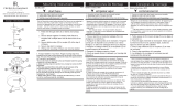
I, II, III, IV, V and VI button:
These six buttons are used to set the
fan speed as follows:
I = minimum speed
II = low speed
III = medium low speed
IV = medium speed
V = medium high speed
VI = high speed
button:
This button turns the fan o.
Reverse button:
This button is to control fan direction.
This button must be pressed while fan is
running (suggested speed IV)
Light button:
This button is to control optional light.
Switch the "D" and "ON" dip switch on the
front of transmitter to decide the light in
"ON/OFF" or "Dimmable" condition.
"SET" code setting button:
Follow the below steps to use the set
button. (Fig. 1)
ON - OFF Slide button: Power switch.
(Fig. 16)
Signal light (Fig. 2)
Pairing Process
With the fan’s power o, restore power to the fan.
Press and hold “SET” button for about 5 seconds
and release. If optional light kit is installed, the light
kit will ash twice and the signal light on the wall
control will come on when the button is pressed.
The fan has completed the pairing process with the
wall control and is ready for use.
NOTE: A single fan can be controlled with as many
as 3 wall controls in one room. Every control will
need to repeat the pairing process based on
instructions above and all controls must be within
30 feet of the fan.
Power switch
Signal light
Fig. 1
Fig. 2
1
2
3
4
5
6
7
14 | hinkley.com
Fig. 3 Fig. 4
SUMMER MODE
(COUNTERCLOCKWISE DIRECTION)
WINTER MODE
(CLOCKWISE DIRECTION)
8
9
Summer Mode and Winter Mode Operation
Summer Mode (forward):
A DOWNWARD airow creates a cooling eect as shown in Figure 3. This allows you to set your air conditioner on a warmer setting without
aecting your comfort.
Winter Mode (Reverse):
An UPWARD airow moves warmer air o the ceiling area as shown in Figure 4. This allows you to set your heating unit on a cooler setting without
aecting your comfort.
CARE AND CLEANING
Periodically it may be necessary to re-tighten blade to blade arm screws or blade arm to motor screws to prevent clicking or humming sound during operation. This is
especially true in climates with broad temperature and humidity ranges.
When dusting the blades, you must support the blade to prevent bending - no pressure should be applied to the blades. If you experience any aws in the operation of
your fan, please check the following points.
©2019 Hinkley Lighting, Inc. | hinkley.com | 15
TROUBLESHOOTING
PROBLEM SOLUTION
FAN WILL
NOT START
FAN SOUNDS
NOISY
FAN WOBBLES
1. Check circuit fuses or breakers.
2. Check wall control LED indicator light. If LED is not illuminated when pushing a button, it is not transmitting a
signal. Please check power to wall control/circuit breaker and all electrical connections.
3. Assure there are no more than 2 fans operating on a circuit through the wall control. Assure that there are no
more than 12 fans operating on a circuit through an on/o wall switch or a breaker (not through a wall control).
4. Assure that the fan in within range of the WiFi (150 ft.) or wall control (30 ft.).
5. Check to assure only one fan is installed in the power circuit.
1. Allow a 24-hour "breaking-in" period. Most noise associated with a new fan will disappear during this time.
2. Make sure all motor housing screws are securely fastened.
3. Make sure the screws that attach the fan blade to the fan are tight.
4. Make sure your ceiling box is secure and rubber isolator pads are used between the mounting bracket and outlet
box.
1. Check that all blade and blade arm screws are secure.
2. If the blade wobble is still noticeable, interchanging two adjacent (side by side) blades can redistribute the weight
and possibly result in smoother operation.
3. Check to assure all dowrods to motor hardware and/or hanger ball are tight.
4. Make sure ceiling box is secure.
CAUTION:
Switch o power supply before carrying out any of these checks.
16 | hinkley.com
ENERGY GUIDE SPECIFICATIONS
AVERAGE PERFORMANCE AND ENERGY INFORMATION
SMART BY BOND
PERFORMANCE
SPECIFICATIONS
STANDARD
HIGH SPEED LOW SPEED
Airflow (CFM)
Energy Use (Watts)
Airflow Eciency (CFM/W)
Energy Costs (Yearly)
Amps
RPMs
HINKLEY SMART FAN OPTIONS (SOLD SEPARATELY):
https://bondhome.io/app
In addition to the included wall control, you can control your Hinkley fan
through the Bond app using the smart technology accessory controls
SOLD SEPARATELY.
To use the app, download it for free from the App Store or Google Play.
Open the app to create your account. You can also login with your Facebook or
Google account.
Next, set up a WiFi connection. You will need the SSID and WiFi password for
the network you want to connect to.
You will receive a prompt to choose the finish of your fan and name your fan
device.
The app will walk you through the main screen and show you how to change
fan speeds, dim the light, set timers or utilize breeze mode.
NOTE: Maximum of 2 fans can operate on a circuit through the wall control.
Maximum of 12 fans can operate on a circuit through an on/o switch or breaker
when utilizing the app for the fan control (without the wall control in the circuit).
8,548
5
19
110231023
33.1
333
9
0.47 0.47
115
5744
5.0
1149
1
0.09
51
HINKLEY IS PROUD TO PROVIDE YOU WITH CEILING FAN
PRODUCTS THAT ENHANCE YOUR SPACE WITH COMFORT,
PURPOSE AND STYLE. AS A FAMILY COMPANY, WE ARE
COMMITTED TO DESIGN, PERFORMANCE AND QUALITY,
AND WHAT’S IMPORTANT TO YOU IS PARAMOUNT TO US.
GLO BAL HEADQUARTERS
33000 Pin Oak Parkway | Avon Lake, Ohio 44012
T (440) 653 5500 | F (440) 653 5555 | hinkley.com
  • Page 1 1
  • Page 2 2
  • Page 3 3
  • Page 4 4
  • Page 5 5
  • Page 6 6
  • Page 7 7
  • Page 8 8
  • Page 9 9
  • Page 10 10
  • Page 11 11
  • Page 12 12
  • Page 13 13
  • Page 14 14
  • Page 15 15
  • Page 16 16
  • Page 17 17
  • Page 18 18
  • Page 19 19
  • Page 20 20
  • Page 21 21
  • Page 22 22
  • Page 23 23
  • Page 24 24
  • Page 25 25
  • Page 26 26
  • Page 27 27
  • Page 28 28
  • Page 29 29
  • Page 30 30
  • Page 31 31
  • Page 32 32
  • Page 33 33
  • Page 34 34
  • Page 35 35
  • Page 36 36
  • Page 37 37
  • Page 38 38
  • Page 39 39
  • Page 40 40
  • Page 41 41
  • Page 42 42
  • Page 43 43
  • Page 44 44
  • Page 45 45
  • Page 46 46
  • Page 47 47
  • Page 48 48
  • Page 49 49
  • Page 50 50
  • Page 51 51
  • Page 52 52
  • Page 53 53
  • Page 54 54
  • Page 55 55
  • Page 56 56
  • Page 57 57
  • Page 58 58
  • Page 59 59
  • Page 60 60

Hinkley 903680FGT-LDD User manual

Category
Household fans
Type
User manual
This manual is also suitable for

Ask a question and I''ll find the answer in the document

Finding information in a document is now easier with AI