Page is loading ...

127411-1
3/99
Printed on
recycled paper.
© 1999 by Crown International, Inc., P.O. Box 1000, Elkhart, IN 46515-1000
U.S.A. Telephone: 219-294-8000. Fax: 219-294-8329.
P.I.P.
modules are
produced by the Professional Audio Division of Crown International, Inc.
Trademark Notice:
Crown
®
,
Macro-Tech
®
,
Com-Tech
®
,
IQ System
®
,
IOC
®
and
P.I.P.
®
are registered trademarks of Crown International, Inc. Other trademarks
are the property of their respective owners.
P.I.P.
–
PA

P.I.P.–PA
Page 2

P.I.P.–PA
Page 3
1 Welcome
Thank you for purchasing the
Crown
P.I.P.-PA
accessory.
P.I.P.
®
modules are designed to
quickly install in the rear panel of
many Crown amplifiers.
P.I.P.
stands for “Programmable Input
Processor.” Their versatile fea-
tures expand the capabilities of
your amplifier and enable you to
customize it for your particular
needs.
The
P.I.P-PA
adds a switchable
balanced low-Z microphone in-
put and a balanced line-level in-
put to each channel of a
Com-
Tech
®
or
Macro-Tech
®
series
amplifier. A remote-control fea-
ture allows you to independently
switch between the mic and line-
level inputs of each channel.
Designed for paging and back-
ground music systems, the
switching circuitry has built-in
delays for pleasing, less abrupt
fades from mic to line and visa
versa.
The mic inputs are transformer
isolated and employ a variable
gain stage. The gain of each
channel can be easily controlled
from the rear panel. Phantom
power is also provided via the
microphone connectors. It can
be disabled by moving a jumper
on the circuit board.
Bass roll-off for each mic input is
provided with a low-cut filter.
These filters roll off at 6 dB/oc-
tave and have a –3 dB frequency
of 150 Hz. They can be indepen-
dently disabled by moving a
jumper on the circuit board.
Finally, each channel includes a
variable-threshold compressor
which is
IOC
®
error-driven at its
maximum setting or acts as an
audio feedback signal-driven
compressor at less than maxi-
mum settings.
Features
❏ Remote switchable balanced
mic and line-level inputs with
custom mute-delay circuitry for
pleasing fades.
❏ Balanced 1:1 isolation transform-
ers for mic inputs.
❏ Adjustable mic input sensitivity.
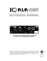
Fig. 1.1 P.I.P.-PA

P.I.P.–PA
Page 4
❏ Phantom power provided for
mic inputs (can be disabled).
❏ Low-frequency filters for mic
inputs (can be disabled).
❏ Variable-threshold error-driven or
audio feedback signal-driven
compressor.
❏ Balanced RFI suppression is
provided at each input.
❏ Gold plated edge-connector
for trouble-free connection to
amp.
❏ Quick-connect barrier con-
nectors provide greater wir-
ing flexibility and make instal-
lation easier.
2 Facilities2 Facilities
2 Facilities2 Facilities
2 Facilities
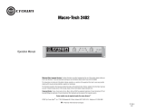
A. Low-Cut Filter Jumper
A 150-Hz, 6-dB/octave low-cut fil-
ter is provided for each mic input
only. (It has no effect upon the
line-level input.) It can be used to
attenuate unwanted pops and
noise which microphones some-
times pick up. The filter of either
channel can be enabled or dis-
abled with the jumpers shown.
The on/off positions of the jump-
ers are labeled on the circuit
board.
B. Compressor Threshold
The threshold of each channel’s
compressor can be adjusted with
these controls. When turned to
their maximum setting (full clock-
wise), the compressors respond
only to the IOC error-signal of their
respective channel. When set
lower, the compressors are sig-
nal-driven by an audio feedback
signal.
C. Phantom Power Jumper
Phantom power (+18 VDC at 9
mA) is provided to the mic inputs
when these jumpers are set to
their “on” position. The on/off po-
sitions of the jumpers are labeled
on the circuit board.
D. Ground Isolation
Jumper
The input grounds can be iso-
lated from the chassis ground by
removing this jumper.
E. Balanced Line Input
Line-level connection is made with
these convenient quick-connect
barrier connectors. Each conduc-
tor is easily attached with screws.
Once the cable is attached, the
connector can be quickly un-
plugged and, if desired, moved to
a different line input.

P.I.P.–PA
Page 5
F. Balanced Mic Input
Low-impedance mic line connec-
tion is made with these connec-
tors in similar fashion as the line-
level inputs (E).
G. Mic Input Gain Control
Use a small, flat-blade screwdriver
to adjust the mic input sensitivity
with these controls.
H. Remote Switch Input
The remote control switches for
both Channel 1 and Channel 2 are
attached to this connector. (The
ground leads are common.) With
no switch attached, the line-level
inputs (E) are normalled to the
amplifier inputs.
Fig. 2.1 Bottom View

P.I.P.–PA
Page 6
3 Installation
Before installing this
P.I.P.
mod-
ule, you’ll want to configure it.
1. Set the microphone phantom
power jumper of each chan-
nel to the desired position. The
on/off positions are labelled
on the circuit board (see Fig-
ure 2.1).
2. Set the microphone low-cut
filter jumpers of each channel
to the desired position. The
on/off positions are labelled
on the circuit board (see Fig-
ure 2.1).
3. Adjust the compressor thresh-
old of each channel. A fifteen-
mark scale is printed on the
circuit board (see Figure 2.1)
which corresponds to the typi-
cal threshold settings shown
in the table in Figure 3.1.
Now you are ready to install the
P.I.P.
in the amplifier.
Fig. 3.1 Compressor Threshold
Settings
Note: These voltage and power levels
are valid only for Stereo (Dual) and
Parallel-Mono modes of operation. The
voltages shown must be doubled and
the power levels recalculated for
Bridged-Mono mode.
Also note: The maximum output power
is strictly limited to the capability of your
amplifier. Any threshold setting above
the maximum output power of your amp
will result in the compressor acting solely
as a “clip” eliminator.
Installation Procedures
You may need a Phillips screw-
driver to remove the existing
P.I.P.
module or panel from your ampli-
fier.
CAUTION: Before connecting
this or any
P.I.P.
to your amplifier,
it is important to turn its level
controls down, turn it off and re-
move the AC power. Don’t touch
the circuitry. Even though the

P.I.P.–PA
Page 7
amplifier is off, there could still be
enough energy remaining to
cause electric shock.
1. Turn down the level controls
(full counterclockwise), turn off
the amplifier and unplug it from
the AC power source.
2. Remove the existing
P.I.P.
mod-
ule or panel (two screws). For
PIP2
amplifiers, this may in-
volve disconnecting the
P.I.P.
from a
PIP2
input adapter (see
Figures 3.3 and 3.4). If a
PIP2
input adapter is already
present, do not remove the rib-
bon cables from the adapter.
Otherwise you will have to re-
connect them in the next step.
3.
Standard P.I.P. Amplifiers
: Align
the edges of the
P.I.P.-PA
in the
P.I.P.
card rails and firmly push
the unit in until it is seated
against the mounting bracket
(see Figure 3.2).
PIP2 Amplifiers:
(Requires a
PIP2
input adapter. Crown part
number Q43528-1.) Connect
the
PIP2
input adapter to the
two input cables of the ampli-
fier (see Figure 3.3). Notice that
the
PIP2
input adapter should
be positioned with the
P.I.P.
edge connector on top and
facing away from the amplifier.
The 20-pin cable (A) is con-
nected first then the 18-pin
cable (B) is connected. Both
A
B
B
A
18 PIN (B)
20 PIN (A)
Q43528-1
FROM AMPLIFIER
P
.I.P
.
M
O
D
U
L
E
BACK PANEL
OF PIP2
AMPLIFIER
PIP2 CONNECTOR
BOARD
Fig.3.3 PIP2 Input Adapter
Connection
Fig. 3.4 Installation into a
PIP2 Amplifier
P.I.P.
MODULE
B
A
C
K
P
A
N
E
L
O
F
A
M
P
L
IF
IE
R
Fig. 3.2 Installation into a
Standard P.I.P. Amplifier
ribbon cables should extend
below the
PIP2
input adapter.
Next, insert the edge connec-
tor of the
P.I.P.-PA
into the
PIP2
input adapter (see Figure 3.4)
and insert the assembly into
the
P.I.P.
opening in the back of
the amplifier.
4. Secure the
P.I.P.-PA
with the
two screws and lock washers

P.I.P.–PA
Page 8
provided. (The lock washers
are important because they
bind the
P.I.P.
to the chassis
ground of the amplifier.)
5. Connect input and output wir-
ing.
6. Plug in the amplifier and turn it
on. Adjust its level controls to a
desired setting.
Do not tamper with the circuitry.
Circuit changes made by unau-
thorized personnel, or unautho-
rized circuit modifications are not
allowed.
Remember: Crown is not liable
for any damage resulting from
overdriving other components in
your sound system.
Important: If the amplifier is used
in either Bridged-Mono or Paral-
lel-Mono mode, you
must turn the
Ch. 2 amplifier level control off
(fully counterclockwise). The in-
put and level control of Ch. 2 are
not defeated in mono mode so
any signal applied to Ch. 2 will
beat against the signal in Ch. 1.
Refer to the amplifier
Reference
Manual
for more information about
Bridged-Mono or Parallel-Mono
modes of operation.
Mono-Mode Wiring
There are two ways to install the
P.I.P.-PA
in a mono configuration.
One method uses the amplifier in
STEREO (Dual) mode. The other
method uses BRIDGED-MONO or
PARALLEL-MONO mode.
If you want to use the
P.I.P.-PA
in
a mono system but still want to
individually control the level of
each amp channel, follow these
instructions: Place the amplifier in
STEREO (Dual) mode, being care-
ful to follow the instructions in your
amplifier's
Reference Manual.
Then simply "daisy chain" the au-
dio signal from one input of the
P.I.P.-PA
to the other. Either the
mic inputs or the line-level inputs
can be paralleled to give both
channels the same signal. (Daisy
chaining the inputs reduces the
input impedance to half.)
You can also mix this technique in
any fashion you desire. For ex-
ample, you could daisy chain a
single microphone to both mic
inputs while feeding the line in-
puts each with a different line-
level feed and visa versa. In this
way you could feed background
music from a radio to one chan-
nel, audio from a tape recorder to
another channel and enable both
channels to be interrupted by the
same paging mic.
The second method for wiring a
mono system gives less flexibility
at the inputs but provides more
power to a single mono output.
This technique requires that you
place your amplifier in either
BRIDGED-MONO or PARALLEL-

P.I.P.–PA
Page 9
MONO mode. Remember to fol-
low the instructions in your
amplifier's
Reference Manual.
Then connect the mono input wir-
ing to the mic and/or line
input of
Channel 1 only. Do not use the
input of Channel 2 while the
amplifier is in BRIDGED-
MONO or PARALLEL-MONO
mode and keep the amplifier’s
Channel 2 level control turned
down.
Input Cable Routing
Because the gain of a Crown
amplifier equipped with a
P.I.P.-
PA
can be quite high (as high as
90 dB) it is very important to exer-
cise care when routing the input
and output cables.
IMPORTANT: Use shielded wire
for mic input cables and
avoidavoid
avoidavoid
avoid
routing them near the output
cables or noise and/or feedback
oscillation may result. It is wise to
take similar precautions with line-
level inputs cables too.
To avoid hum, do not route the
input cables near power cables.
Switching Between Mic/Line
The line-level inputs are the de-
fault inputs if no switch is attached
to select the mic inputs. In this
case, each mic input is attenu-
ated 54 dB while each line input is
delivered to the amplifier.
When the remote switch connec-
tion is shorted (that is, a switch is
installed and turned on) the line-
level input is attenuated 30 dB
and the mic input is delivered to
the amplifier.
A timed fader circuit causes the
switch from line to mic and mic to
line to be a smooth transition. The
intent is to create a more pleasing
transition for situations where the
line-level input is used to feed
background music and the mic
input is used for paging.
When the switch is activated, the
line-level input is muted after a
delay of 10 msec. Because it is
muted only 30 dB it is still barely
audible. The mic input turns on
almost immediately to insure that
no syllables of speech are lost,
giving an abrupt transition from
background music to paging.
When the switch is opened the
mic input is quickly muted 54 dB
in about 3 msec. The line-level
input is turned back on after a
lengthy delay of 1.5 seconds, pro-
viding a more pleasing fade back
to music after the page.
The remote line can also be con-
trolled with a +5 to +24 VDC logic
line. For example, you could use
the Auxiliary control feature of an
IQ–P.I.P.
or an
MPX/SMX-6
multi-
plexer to control the mic/line
switching with an
IQ System
®
. To
do this, add a 20 K ohm “pull
down” resistor across each re-
mote line. When the logic line is

P.I.P.–PA
Page 10
“Hi” the line-level input is enabled.
When it is “Lo” the mic input is
enabled.
Figure 3.5 shows how to connect
a remote switch (or logic line) to
each channel using the remote
connector.
Ground Isolation
If present, ground loop problems
can be reduced by unsoldering or
cutting and removing the ground
jumper shown in Figure 2.1.
When removed, the signal ground
is isolated from the chassis ground
by a 2.7 ohm resistor as shown
below:
Fig. 3.5 Remote Switch Wiring
Fig. 3.6 Ground Isolation

P.I.P.–PA
Page 11
4 Specifications
Note: All specifications referenced to a
0.775 V input signal.
Signal to Noise:
Line: Nomi-
nally –80 dB from 20 Hz to 20
kHz. Mic: Nominally –118 dB
equivalent input noise, 20 Hz to
20 kHz (Rs=150Ω).
Frequency Response:
Line:
±0.5 dB from 20 Hz to 20 kHz.
Mic: ±1 dB from 50 Hz to 15 kHz.
Common Mode Rejection:
Bet-
ter than 70 dB at 60 Hz.
Nominal Input Impedance:
Line:
50 K ohms balanced and 25
K ohms unbalanced. Mic: 2
K ohms balanced.
Phantom Power:
18 VDC at 9
mA. (Can be disabled with a
jumper block on the circuit
board.)
Recommended Source Imped-
ance: Line: 600 ohms. Mic: 250
ohms.
Maximum Input Level: Line: +22
dB. Mic: +8 dB.
Nominal Gain: Line: Unity. Mic:
Adjustable from 20 to 50 dB with
user-accessible gain pots.
Compressor: Driven by both the
audio signal and by the
IOC
error
signal. The adjustable threshold
is controlled by a pot on the cir-
cuit board and the attack and
decay times are nominally fixed
at 20 msec and 200 msec, re-
spectively. At its maximum set-
ting it functions as an error-driven
compressor and is activated by
the
IOC
signal. Below the maxi-
mum setting it is driven by the
audio feedback signal.
Remote Mic/Line Switch: The
mic/line priority of each channel
can be remotely controlled using
the “Remote” connector pro-
vided. Each channel is controlled
independently. When mic prior-
ity is selected, the line-level input
is attenuated 30 dB. When line-
level priority is selected, the mic
input is attenuated by 54 dB. A
delay circuit provides a smooth
fade from mic to line and visa
versa.
Dimensions: 6
3
/
8
x 1
7
/
8
x 3
7
/
8
in
(16.2 x 4.8 x 9.8 cm).
Weight: 12 ounces (340 grams).

P.I.P.–PA
Page 12
5 Schematic
Notes:Notes:
Notes:Notes:
Notes:
1. All resistors are in ohms,
1
/
4
W, 5% unless otherwise specified.
Electronic image for this figure
was not included due to quality
considerations. Please refer to
the printed documentation.

P.I.P.–PA
Page 13
2. All capacitors are in microfarads unless otherwise specified.
Electronic image for this figure
was not included due to quality
considerations. Please refer to
the printed documentation.

P.I.P.–PA
Page 14
6 Service
This unit has very sophis-
ticated circuitry which should
only be serviced by a fully
trained technician.
6.1 Worldwide Service
Service may be obtained from
an authorized service center.
(Contact your local Crown/
Amcron representative or our
office for a list of authorized
service centers.) To obtain
service, simply present the bill
of sale as proof of purchase
along with the defective unit to
an authorized service center.
They will handle the
necessary paperwork and
repair.
Remember to transport your
unit in the original factory
pack.
Always use the
original factory pack
to transport the unit.
choose either. It is important
that you have your copy of the
bill of sale as your proof of
purchase.
6.2.1 Service at a North
American Service Center
Simply present your bill of
sale along with the defective
unit to an authorized service
center to obtain service. They
will handle the necessary
paperwork and repair.
Remember to transport the
unit in the original factory
pack. A list of authorized
service centers in your area
can be obtained from our
Technical Support Group.
6.2.2 Factory Service
To obtain factory service, fill
out the
service informationservice information
service informationservice information
service information
pagepage
pagepage
page found in the back of this
manual and send it along with
your proof of purchase and
the defective unit to the
Crown factory.
For warranty service, we will
pay for ground shipping both
ways in the United States.
Contact Crown Factory
Service or Technical Support
to obtain prepaid shipping
labels prior to sending the
unit. Or, if you prefer, you may
prepay the cost of shipping,
6.2 North American Service
Service may be obtained in
one of two ways: from an
authorized service center or
from the factory. You may

P.I.P.–PA
Page 15
Crown Audio Customer Service
Technical Support / Factory Service
Plant 2 SW, 1718 W. Mishawaka Rd.,
Elkhart, Indiana 46517 U.S.A.
Telephone:
219-294-8200
800-342-6939
(North America,
Puerto Rico, and
Virgin Islands only)
Facsimile:
219-294-8301
(Technical Support)
219-294-8124
(Factory Service)
Fax Back:
219-293-9200 or
800-294-4094
(North America only)
219-294-8100
(International)
Internet:
www.crownaudio.com
and Crown will reimburse you.
Send copies of the shipping
receipts to Crown to receive
reimbursement.
Your repaired unit will be
returned via UPS ground.
Please contact us if other
arrangements are required.
Factory Service Shipping
Instructions:
1. When sending a Crown
product to the factory for
service, be sure to fill out
the service information
form that follows and en-
close it inside your unit’s
shipping pack. Do not
send the service infor-
mation form separately.
2. To ensure the safe trans-
portation of your unit to
the factory, ship it in an
original factory packing
container. If you don’t
have one, call or write
Crown’s Parts Depart-
ment. With the exception
of polyurethane or
wooden crates, any
other packing material
will not be sufficient to
withstand the stress of
shipping.
Do not useDo not use
Do not useDo not use
Do not use
loose, small size pack-loose, small size pack-
loose, small size pack-loose, small size pack-
loose, small size pack-
ing materials.ing materials.
ing materials.ing materials.
ing materials.
3. Do not ship the unit in
any kind of cabinet
(wood or metal). Ignoring
this warning may result in
extensive damage to the
unit and the cabinet. Ac-
cessories are not
needed—do not send
the instruction manual,
cables and other hard-
ware.
If you have any questions,
please call or write the Crown
Technical Support Group.

P.I.P.–PA
Page 16
NORTH AMERICA
SUMMARY OF WARRANTY
The Crown Audio Division of Crown International, Inc., 1718 West Mishawaka Road,
Elkhart, Indiana 46517-4095 U.S.A. warrants to you, the ORIGINAL PURCHASER and
ANY SUBSEQUENT OWNER of each NEW Crown product, for a period of three (3) years
from the date of purchase by the original purchaser (the “warranty period”) that the new
Crown product is free of defects in materials and workmanship. We further warrant the
new Crown product regardless of the reason for failure, except as excluded in this
Warranty.
ITEMS EXCLUDED FROM THIS CROWN WARRANTY
This Crown Warranty is in effect only for failure of a new Crown product which occurred
within the Warranty Period. It does not cover any product which has been damaged
because of any intentional misuse, accident, negligence, or loss which is covered under
any of your insurance contracts. This Crown Warranty also does not extend to the new
Crown product if the serial number has been defaced, altered, or removed.
WHAT THE WARRANTOR WILL DO
We will remedy any defect, regardless of the reason for failure (except as excluded), by
repair, replacement, or refund. We may not elect refund unless you agree, or unless we
are unable to provide replacement, and repair is not practical or cannot be timely made.
If a refund is elected, then you must make the defective or malfunctioning product
available to us free and clear of all liens or other encumbrances. The refund will be equal
to the actual purchase price, not including interest, insurance, closing costs, and other
finance charges less a reasonable depreciation on the product from the date of original
purchase. Warranty work can only be performed at our authorized service centers or
at the factory. We will remedy the defect and ship the product from the service center
or our factory within a reasonable time after receipt of the defective product at our
authorized service center or our factory. All expenses in remedying the defect, including
surface shipping costs in the United States, will be borne by us. (You must bear the
expense of shipping the product between any foreign country and the port of entry in
the United States and all taxes, duties, and other customs fees for such foreign
shipments.)
HOW TO OBTAIN WARRANTY SERVICE
You must notify us of your need for warranty service not later than ninety (90) days after
expiration of the warranty period. All components must be shipped in a factory pack,
which, if needed, may be obtained from us free of charge. Corrective action will be taken
within a reasonable time of the date of receipt of the defective product by us or our
authorized service center. If the repairs made by us or our authorized service center are
not satisfactory, notify us or our authorized service center immediately.
DISCLAIMER OF CONSEQUENTIAL & INCIDENTAL DAMAGES
YOU ARE NOT ENTITLED TO RECOVER FROM US ANY INCIDENTAL DAMAGES
RESULTING FROM ANY DEFECT IN THE NEW CROWN PRODUCT. THIS INCLUDES
ANY DAMAGE TO ANOTHER PRODUCT OR PRODUCTS RESULTING FROM SUCH A
DEFECT.
SOME STSOME ST
SOME STSOME ST
SOME ST
AA
AA
A
TES DO NOT ALLOW THE EXCLUSION OR LIMITTES DO NOT ALLOW THE EXCLUSION OR LIMIT
TES DO NOT ALLOW THE EXCLUSION OR LIMITTES DO NOT ALLOW THE EXCLUSION OR LIMIT
TES DO NOT ALLOW THE EXCLUSION OR LIMIT
AA
AA
A
TIONS OFTIONS OF
TIONS OFTIONS OF
TIONS OF
INCIDENTINCIDENT
INCIDENTINCIDENT
INCIDENT
AL OR CONSEQUENTIAL DAMAGES, SO THE ABOVE LIMITAL OR CONSEQUENTIAL DAMAGES, SO THE ABOVE LIMIT
AL OR CONSEQUENTIAL DAMAGES, SO THE ABOVE LIMITAL OR CONSEQUENTIAL DAMAGES, SO THE ABOVE LIMIT
AL OR CONSEQUENTIAL DAMAGES, SO THE ABOVE LIMIT
AA
AA
A
TION ORTION OR
TION ORTION OR
TION OR
EXCLUSION MAEXCLUSION MA
EXCLUSION MAEXCLUSION MA
EXCLUSION MA
Y NOT APPLY NOT APPL
Y NOT APPLY NOT APPL
Y NOT APPL
Y TO YOU.Y TO YOU.
Y TO YOU.Y TO YOU.
Y TO YOU.
WARRANTY ALTERATIONS
No person has the authority to enlarge, amend, or modify this Crown Warranty. This
Crown Warranty is not extended by the length of time which you are deprived of the use
of the new Crown product. Repairs and replacement parts provided under the terms of
this Crown Warranty shall carry only the unexpired portion of this Crown Warranty.
DESIGN CHANGES
We reserve the right to change the design of any product from time to time without notice
and with no obligation to make corresponding changes in products previously
manufactured.
LEGAL REMEDIES OF PURCHASER
THIS CROWN WARRANTY GIVES YOU SPECIFIC LEGAL RIGHTS, YOU MAY ALSO
HAVE OTHER RIGHTS WHICH VARY FROM STATE TO STATE. No action to enforce this
Crown Warranty shall be commenced later than ninety (90) days after expiration of the
warranty period.
THIS STATEMENT OF WARRANTY SUPERSEDES ANY OTHERS
CONTAINED IN THIS MANUAL FOR CROWN PRODUCTS.
9/90
YEAR
3
THREE YEAR
FULL WARRANTY
Telephone: 219-294-8200. Facsimile: 219-294-8301

P.I.P.–PA
Page 17
WORLDWIDE
SUMMARY OF WARRANTY
The Crown Audio Division of Crown International, Inc., 1718 West Mishawaka Road,
Elkhart, Indiana 46517-4095 U.S.A. warrants to you, the ORIGINAL PURCHASER and
ANY SUBSEQUENT OWNER of each NEW Crown
1
product, for a period of three (3)
years from the date of purchase by the original purchaser (the “warranty period”) that
the new Crown product is free of defects in materials and workmanship, and we further
warrant the new Crown product regardless of the reason for failure, except as excluded
in this Crown Warranty.
1
Note: If your unit bears the name “Amcron,” please substitute it for the name “Crown”
in this warranty.
ITEMS EXCLUDED FROM THIS CROWN WARRANTY
This Crown Warranty is in effect only for failure of a new Crown product which occurred
within the Warranty Period. It does not cover any product which has been damaged
because of any intentional misuse, accident, negligence, or loss which is covered under
any of your insurance contracts. This Crown Warranty also does not extend to the new
Crown product if the serial number has been defaced, altered, or removed.
WHAT THE WARRANTOR WILL DO
We will remedy any defect, regardless of the reason for failure (except as excluded), by
repair, replacement, or refund. We may not elect refund unless you agree, or unless we
are unable to provide replacement, and repair is not practical or cannot be timely made.
If a refund is elected, then you must make the defective or malfunctioning product
available to us free and clear of all liens or other encumbrances. The refund will be equal
to the actual purchase price, not including interest, insurance, closing costs, and other
finance charges less a reasonable depreciation on the product from the date of original
purchase. Warranty work can only be performed at our authorized service centers. We
will remedy the defect and ship the product from the service center within a reasonable
time after receipt of the defective product at our authorized service center.
HOW TO OBTAIN WARRANTY SERVlCE
You must notify us of your need for warranty service not later than ninety (90) days after
expiration of the warranty period. All components must be shipped in a factory pack.
Corrective action will be taken within a reasonable time of the date of receipt of the
defective product by our authorized service center. If the repairs made by our
authorized service center are not satisfactory, notify our authorized service center
immediately.
DISCLAIMER OF CONSEQUENTIAL & INCIDENTAL DAMAGES
YOU ARE NOT ENTITLED TO RECOVER FROM US ANY INCIDENTAL DAMAGES
RESULTING FROM ANY DEFECT IN THE NEW CROWN PRODUCT. THIS INCLUDES
ANY DAMAGE TO ANOTHER PRODUCT OR PRODUCTS RESULTING FROM SUCH A
DEFECT.
WARRANTY ALTERATIONS
No person has the authority to enlarge, amend, or modify this Crown Warranty. This
Crown Warranty is not extended by the length of time which you are deprived of the use
of the new Crown product. Repairs and replacement parts provided under the terms of
this Crown Warranty shall carry only the unexpired portion of this Crown Warranty.
DESIGN CHANGES
We reserve the right to change the design of any product from time to time without notice
and with no obligation to make corresponding changes in products previously
manufactured.
LEGAL REMEDIES OF PURCHASER
No action to enforce this Crown Warranty shall be commenced later than ninety (90)
days after expiration of the warranty period.
THIS STATEMENT OF WARRANTY SUPERSEDES ANY OTHERS
CONTAINED IN THIS MANUAL FOR CROWN PRODUCTS.
9/90
THREE YEAR
FULL WARRANTY
YEAR
3
Telephone: 219-294-8200. Facsimile: 219-294-8301

P.I.P.–PA
Page 18

P.I.P.–PA
Page 19
Crown Factory Service Information
Shipping Address: Crown Factory Service,
Plant 2 SW, 1718 W. Mishawaka Rd., Elkhart, IN U.S.A. 46517
Phone: 1-800-342-6939 or 1-219-294-8200 Fax: 1-219-294-8124
Owner’s Name: __________________________________________________________
Shipping Address:_______________________________________________________
Phone Number: _______________________ Fax Number: ___________________
Model: _______________________________ Serial Number: _________________
Purchase Date:__________________________________________________________
NATURE OF PROBLEM
(Be sure to describe the conditions that existed when the
problem occurred and what attempts were made to correct it.)
_______________________________________________________________________
_______________________________________________________________________
_______________________________________________________________________
_______________________________________________________________________
_______________________________________________________________________
Other equipment in your system: __________________________________________
_______________________________________________________________________
_______________________________________________________________________
_______________________________________________________________________
_______________________________________________________________________
If warranty has expired, payment will be:
❏❏
❏❏
❏ Cash/Check
❏❏
❏❏
❏ VISA
❏❏
❏❏
❏ MasterCard
❏❏
❏❏
❏ C.O.D.
Card Number:___________________________
Exp. Date: __________ Signature:____________________________
ENCLOSE THIS PORTION WITH THE UNIT.
DO NOT MAIL SEPARATELY.

For Technical Support contact:
Crown Audio Division Technical Support Group
Plant 2 SW, 1718 W. Mishawaka Rd., Elkhart, Indiana 46517 U.S.A.
Phone: 800-342-6939 (North America, Puerto Rico and Virgin Islands) or 219-294-8200
Fax: 219-294-8301 Fax Back (North America only): 800-294-4094 or 219-293-9200
Fax Back (International): 219-294-8100
Internet: http://www.crownaudio.com
/