Page is loading ...

®
THE PROFESSIONAL AUDIO DIVISION OF CROWN INTERNATIONAL, INC.
Printed on
recycled paper.
©1995 by CROWN INTERNATIONAL, INC.
P.O. Box 1000, Elkhart, Indiana 46515-1000
Telephone: 219-294-8000
Studio Reference
™
PROFESSIONAL STUDIO AMPLIFIERS
OWNER’S MANUAL
Exported to select countries as Amcron.
®
®
Trademark Notice:
Studio Reference
,
™
Smart Amp
,
™
MPX-6
,
™
SMX-6
,
™
AMB-5
,
™
and
grounded bridge
™
are trademarks and
Crown
,
®
IOC
®
,
ODEP
,
®
IQ System
®
and
P.I.P.
®
are registered trademarks of
Crown International, Inc. Other trademarks are the property of their respective owners.
K80604-0
8/95

WORLDWIDE
SUMMARY OF WARRANTY
The Crown Audio Division of Crown International, Inc., 1718 West
Mishawaka Road, Elkhart, Indiana 46517-4095 U.S.A. warrants to you,
the ORIGINAL PURCHASER and ANY SUBSEQUENT OWNER of each
NEW Crown
1
product, for a period of three (3) years from the date of
purchase by the original purchaser (the “warranty period”) that the new
Crown product is free of defects in materials and workmanship, and we
further warrant the new Crown product regardless of the reason for
failure, except as excluded in this Crown Warranty.
1
Note: If your unit bears the name “Amcron,” please substitute it for the
name “Crown” in this warranty.
ITEMS EXCLUDED FROM THIS CROWN WARRANTY
This Crown Warranty is in effect only for failure of a new Crown product
which occurred within the Warranty Period. It does not cover any product
which has been damaged because of any intentional misuse, accident,
negligence, or loss which is covered under any of your insurance
contracts. This Crown Warranty also does not extend to the new Crown
product if the serial number has been defaced, altered, or removed.
WHAT THE WARRANTOR WILL DO
We will remedy any defect, regardless of the reason for failure (except as
excluded), by repair, replacement, or refund. We may not elect refund
unless you agree, or unless we are unable to provide replacement, and
repair is not practical or cannot be timely made. If a refund is elected, then
you must make the defective or malfunctioning product available to us
free and clear of all liens or other encumbrances. The refund will be equal
to the actual purchase price, not including interest, insurance, closing
costs, and other finance charges less a reasonable depreciation on the
product from the date of original purchase. Warranty work can only be
performed at our authorized service centers. We will remedy the defect
and ship the product from the service center within a reasonable time after
receipt of the defective product at our authorized service center. All
expenses in remedying the defect, including surface shipping costs to the
nearest authorized service center, will be borne by us. (You must bear the
expense of all taxes, duties and other customs fees when transporting the
product.)
HOW TO OBTAIN WARRANTY SERVICE
You must notify us of your need for warranty service not later than ninety
(90) days after expiration of the warranty period. All components must be
shipped in a factory pack. Corrective action will be taken within a
reasonable time of the date of receipt of the defective product by our
authorized service center. If the repairs made by our authorized service
center are not satisfactory, notify our authorized service center
immediately.
DISCLAIMER OF CONSEQUENTIAL AND INCIDENTAL
DAMAGES
YOU ARE NOT ENTITLED TO RECOVER FROM US ANY
INCIDENTAL DAMAGES RESULTING FROM ANY DEFECT IN THE
NEW CROWN PRODUCT. THIS INCLUDES ANY DAMAGE TO
ANOTHER PRODUCT OR PRODUCTS RESULTING FROM SUCH A
DEFECT.
WARRANTY ALTERATIONS
No person has the authority to enlarge, amend, or modify this Crown
Warranty. This Crown Warranty is not extended by the length of time
which you are deprived of the use of the new Crown product. Repairs and
replacement parts provided under the terms of this Crown Warranty shall
carry only the unexpired portion of this Crown Warranty.
DESIGN CHANGES
We reserve the right to change the design of any product from time to time
without notice and with no obligation to make corresponding changes in
products previously manufactured.
LEGAL REMEDIES OF PURCHASER
No action to enforce this Crown Warranty shall be commenced later than
ninety (90) days after expiration of the warranty period.
THIS STATEMENT OF WARRANTY SUPERSEDES ANY OTHERS
CONTAINED IN THIS MANUAL FOR CROWN PRODUCTS.
Telephone: 219-294-8200. Facsimile: 219-294-8301
9/90
Y
E
A
R
3
YEAR
3
NORTH AMERICA
SUMMARY OF WARRANTY
The Crown Audio Division of Crown International, Inc., 1718 West Mishawaka
Road, Elkhart, Indiana 46517-4095 U.S.A. warrants to you, the ORIGINAL
PURCHASER and ANY SUBSEQUENT OWNER of each NEW Crown
product, for a period of three (3) years from the date of purchase by the original
purchaser (the “warranty period”) that the new Crown product is free of defects
in materials and workmanship, and we further warrant the new Crown product
regardless of the reason for failure, except as excluded in this Crown Warranty.
ITEMS EXCLUDED FROM THIS CROWN WARRANTY
This Crown Warranty is in effect only for failure of a new Crown product which
occurred within the Warranty Period. It does not cover any product which has
been damaged because of any intentional misuse, accident, negligence, or
loss which is covered under any of your insurance contracts. This Crown
Warranty also does not extend to the new Crown product if the serial number
has been defaced, altered, or removed.
WHAT THE WARRANTOR WILL DO
We will remedy any defect, regardless of the reason for failure (except as
excluded), by repair, replacement, or refund. We may not elect refund unless
you agree, or unless we are unable to provide replacement, and repair is not
practical or cannot be timely made. If a refund is elected, then you must make
the defective or malfunctioning product available to us free and clear of all liens
or other encumbrances. The refund will be equal to the actual purchase price,
not including interest, insurance, closing costs, and other finance charges less
a reasonable depreciation on the product from the date of original purchase.
Warranty work can only be performed at our authorized service centers or at
the factory. We will remedy the defect and ship the product from the service
center or our factory within a reasonable time after receipt of the defective
product at our authorized service center or our factory. All expenses in
remedying the defect, including surface shipping costs in the United States, will
be borne by us. (You must bear the expense of shipping the product between
any foreign country and the port of entry in the United States and all taxes,
duties, and other customs fees for such foreign shipments.)
HOW TO OBTAIN WARRANTY SERVICE
You must notify us of your need for warranty service not later than ninety (90)
days after expiration of the warranty period. All components must be shipped
in a factory pack, which, if needed, may be obtained from us free of charge.
Corrective action will be taken within a reasonable time of the date of receipt
of the defective product by us or our authorized service center. If the repairs
made by us or our authorized service center are not satisfactory, notify us or
our authorized service center immediately.
DISCLAIMER OF CONSEQUENTIAL AND INCIDENTAL DAMAGES
YOU ARE NOT ENTITLED TO RECOVER FROM US ANY INCIDENTAL
DAMAGES RESULTING FROM ANY DEFECT IN THE NEW CROWN
PRODUCT. THIS INCLUDES ANY DAMAGE TO ANOTHER PRODUCT OR
PRODUCTS RESULTING FROM SUCH A DEFECT. SOME STATES DO
NOT ALLOW THE EXCLUSION OR LIMITATIONS OF INCIDENTAL OR
CONSEQUENTIAL DAMAGES, SO THE ABOVE LIMITATION OR
EXCLUSION MAY NOT APPLY TO YOU.
WARRANTY ALTERATIONS
No person has the authority to enlarge, amend, or modify this Crown Warranty.
This Crown Warranty is not extended by the length of time which you are
deprived of the use of the new Crown product. Repairs and replacement parts
provided under the terms of this Crown Warranty shall carry only the unexpired
portion of this Crown Warranty.
DESIGN CHANGES
We reserve the right to change the design of any product from time to time
without notice and with no obligation to make corresponding changes in
products previously manufactured.
LEGAL REMEDIES OF PURCHASER
THIS CROWN WARRANTY GIVES YOU SPECIFIC LEGAL RIGHTS, YOU
MAY ALSO HAVE OTHER RIGHTS WHICH VARY FROM STATE TO
STATE. No action to enforce this Crown Warranty shall be commenced later
than ninety (90) days after expiration of the warranty period.
THIS STATEMENT OF WARRANTY SUPERSEDES ANY OTHERS
CONTAINED IN THIS MANUAL FOR CROWN PRODUCTS.
Telephone: 219-294-8200. Facsimile: 219-294-8301
9/90
THREE YEAR
FULL WARRANTY

The information furnished in this manual does not include all of the details of design, production, or variations of the
equipment. Nor does it cover every possible situation which may arise during installation, operation or
maintenance. If your unit bears the name “Amcron,” please substitute it for the name “Crown” in this manual. If you
need special assistance beyond the scope of this manual, please contact our Technical Support Group.
Crown Audio Division Technical Support Group
57620 C.R. 105, Elkhart, Indiana 46517 U.S.A.
Phone: 800-342-6939 (U.S.A.) or 219-294-8200 Fax: 219-294-8301
IMPORTANT
STUDIO REFERENCE AMPLIFIERS
REQUIRE CLASS 1 OUTPUT WIRING.
WATCH FOR THESE SYMBOLS:
The lightning bolt
triangle is used to
alert the user to the
risk of electric shock.
The exclamation point
triangle is used to alert the
user to important operating or
maintenance instructions.
Magnetic Field
CAUTION! Do not locate sensitive high-gain equip-
ment such as preamplifiers or tape decks directly
above or below the unit. Because this amplifier has
a high power density, it has a strong magnetic field
which can induce hum into unshielded devices that
are located nearby. The field is strongest just above
and below the unit.
If an equipment rack is used, we recommend locating
the amplifier(s) in the bottom of the rack and the
preamplifier or other sensitive equipment at the top.
TO PREVENT ELECTRIC SHOCK DO
NOT REMOVE TOP OR BOTTOM
COVERS. NO USER SERVICEABLE
PARTS INSIDE. REFER SERVICING
TO QUALIFIED SERVICE PERSON-
NEL. DISCONNECT POWER CORD
BEFORE REMOVING REAR INPUT
MODULE TO ACCESS GAIN SWITCH.
C A U T I O N
RISK OF ELECTRIC SHOCK
DO NOT OPEN
A V I S
RISQUE DE CHOC ÉLECTRIQUE
N’OUVREZ PAS
À PRÉVENIR LE CHOC
ÉLECTRIQUE N’ENLEVEZ
PAS LES COUVERTURES.
RIEN DES PARTIES
UTILES À L’INTÉRIEUR.
DÉBRANCHER LA BORNE
AVANT D’OUVRIR LA
MODULE EN ARRIÈRE.
WARNING
TO REDUCE THE RISK OF ELECTRIC
SHOCK, DO NOT EXPOSE THIS
EQUIPMENT TO RAIN OR MOISTURE!

Page 4
Studio Reference
II
II
I
&
IIII
IIII
II
Professional Studio Amplifiers
CONTENTS
1 Welcome.......................................................................... 7
1.1 Features ................................................................... 7
2 Facilities .......................................................................... 8
3 Installation ..................................................................... 10
3.1 Mounting ................................................................ 10
3.2 Cooling ................................................................... 10
3.3 Wiring ..................................................................... 11
3.3.1 Stereo (Two-Channel) Operation ................... 12
3.3.2 Bridge-Mono Operation ................................ 12
3.3.3 Parallel-Mono Operation ............................... 13
3.3.4 Input Connection .......................................... 14
3.3.5 Output Connection ....................................... 16
3.3.6 Additional Load Protection ............................ 18
3.4 AC Mains Power ..................................................... 18
4 Operation....................................................................... 19
4.1 Precautions ............................................................. 19
4.2 Indicators................................................................ 19
4.3 Protection Systems ................................................. 20
4.3.1
ODEP ...........................................................
21
4.3.2 Standby Mode .............................................. 21
4.3.3 Transformer Thermal Protection .................... 21
4.3.4 Circuit Breaker ............................................. 22
4.4 Controls .................................................................. 22
4.5 Filter Cleaning ......................................................... 23
5 Technical Information ................................................... 24
5.1 Overview ................................................................ 24
5.2 Circuit Theory ......................................................... 24
5.2.1 Stereo Operation .......................................... 24
5.2.2 Bridge-Mono Operation ................................ 26
5.2.3 Parallel-Mono Operation ............................... 26
6 Specifications ................................................................ 27
7 AC Power Draw & Thermal Dissipation ........................ 36
8 Accessories ................................................................... 38
8.1
P.I.P.
Modules ......................................................... 38
9 Service........................................................................... 40
9.1 Worldwide Service .................................................. 40
9.2 North American Service .......................................... 40
9.2.1 Service at a North American Service Center .. 40
9.2.2 Factory Service ............................................ 40

Page 5
Studio Reference
II
II
I
&
IIII
IIII
II
Professional Studio Amplifiers
ILLUSTRATIONS
1.1
Studio Reference
I Amplifier ........................................... 6
2.1 Front Facilities ................................................................. 8
2.2 Rear Facilities ................................................................. 9
3.1 Mounting Dimensions .................................................... 10
3.2 Removing an End Cap .................................................. 10
3.3 Top View of a Rack-Mounted Unit .................................. 10
3.4 Proper Air Flow with a Rack-Mounted Blower ................ 11
3.5 Stereo Wiring ................................................................ 11
3.6 Bridge-Mono Wiring ...................................................... 12
3.7 Parallel-Mono Wiring ..................................................... 13
3.8 Unbalanced Input Wiring ............................................... 14
3.9 Balanced Input Wiring ................................................... 14
3.10 Balanced and Unbalanced Phone Plugs ....................... 14
3.11 Subsonic Filter Capacitors ............................................ 15
3.12 Unbalanced RF Filters ................................................... 15
3.13 Balanced RF Filters ....................................................... 15
3.14 Wire Size Nomograph ................................................... 16
3.15 Inductive Load (Transformer) Network ........................... 17
3.16 Loudspeaker Fuse Nomograph ..................................... 18
4.1 Indicators ...................................................................... 19
4.2
Studio Reference
Indicator States .................................. 20
4.3 Removing a Handle ...................................................... 22
4.4 Meter Switches ............................................................. 23
4.5 Input Sensitivity and Ground Lift Switches ..................... 23
5.1 Circuit Block Diagram ................................................... 25
6.1
Studio Reference
I Minimum Power Matrix .................... 29
6.2
Studio Reference
II Minimum Power Matrix .................. 30
6.3
Studio Reference
I Maximum Power Matrix ................... 31
6.4
Studio Reference
II Maximum Power Matrix ................. 32
6.5 Typical Frequency Response ........................................ 33
6.6 Typical Damping Factor ................................................ 33
6.7 Typical Output Impedance ............................................ 33
6.8 Typical Phase Response ............................................... 34
6.9 Typical Common Mode Rejection .................................. 34
6.10 Typical Crosstalk ........................................................... 35
7.1
Studio Reference
I Power Draw, Current Draw and
Thermal Dissipation at Various Duty Cycles ................... 36
7.2
Studio Reference
II Power Draw, Current Draw and
Thermal Dissipation at Various Duty Cycles ................... 37
8.1 Installing a
P.I.P.
Module ............................................... 38

Page 6
Studio Reference
II
II
I
&
IIII
IIII
II
Professional Studio Amplifiers
Unpacking Instructions
Please unpack and inspect your new amplifier for
any damage that may have occurred during transit.
If damage is found, notify the transportation com-
pany immediately. Only you, the consignee, may ini-
tiate a claim for shipping damage. Crown will be
happy to cooperate fully as needed. Save the ship-
ping carton as evidence of damage for the shipper’s
inspection.
Even if the unit arrived in perfect condition, as most
do, save all packing materials so you will have them
if you ever need to transport the unit. NEVER SHIP
THE UNIT WITHOUT THE FACTORY PACK.
®
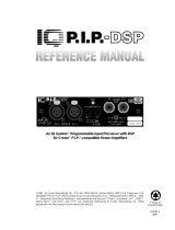
Fig. 1.1 Studio Reference
I
Amplifier

Page 7
Studio Reference
II
II
I
&
IIII
IIII
II
Professional Studio Amplifiers
1 Welcome
The stunning realism you will experience when listen-
ing to a Crown
Studio Reference
™
amplifier will
redefine your expectations. The evolution of this studio
standard ushers in a new era of powerful, ultraquiet
amplifiers capable of faithfully reproducing the most
demanding signals that state-of-the-art 20-bit digital
recording systems can offer. This kind of sonic integrity
does not happen accidentally. It demands the leader-
ship and technical excellence for which Crown has
long been known.
With the best transfer function in the industry, ultra-high
dynamic range and extraordinary damping factor, your
Studio Reference
amplifier comes closer to the ideal
“straight wire with gain” than any other amplifier. As
you listen, it will become apparent—the amplifier’s low-
frequency transient response is the standard by which
all others must be judged.
We have taken great care at every step in the creation
of your amplifier—from the selection of its components
to the routing of each wire. It is our goal to provide you
with total satisfaction. This is one reason why we have
spent considerable effort in providing you with the
most complete
Owner’s Manual
in the business.
Please read it carefully—especially the instructions,
warnings and cautions. It will help you successfully
install and use your new amplifier. Be sure to read
Sections 3.3.2 and 3.3.3 if you plan to use one of the
amplifier’s two mono modes.
Please send in your warranty registration card today
and save your bill of sale because it is your official
proof of purchase. We hope you enjoy your new ampli-
fier, and thank you for choosing Crown.
1.1 Features
Studio Reference
amplifiers integrate several cutting
edge technologies that make them the most accurate
reference amplifiers available. For example, in Stereo
mode each channel can actually be treated as a sepa-
rate amplifier because of its separate high-voltage
power supplies and ultra-low crosstalk. Here are some
of its many impressive features:
❏ Crown’s unconventional
grounded bridge
™
circuitry
delivers incredible voltage swings without using
stressful output transistor configurations like other more
traditional amplifiers. This results in significantly lower
distortion and superior reliability.
❏ Patented
ODEP
®
(Output Device Emulation Protection)
circuitry detects and compensates for overheating and
overload to keep the amplifier working when others
would fail.
❏
IOC
®
(Input/Output Comparator) circuitry immediately
alerts you of any distortion that exceeds 0.05% to
provide dynamic
proof of distortion-free performance
.
❏
P.I.P.
(Programmable Input Processor) connector
accepts accessories that tailor your amplifier to suit
specific applications.
❏ Extremely wide dynamic range capable of accurately
reproducing 20-bit digital recordings.
❏ Ultra-high damping factor delivers superior loudspeaker
motion control for the cleanest, tightest, chest-thumping
bottom end you’ve ever felt—or heard.
❏ Super-low harmonic and intermodulation distortion give
your amplifier
the best transfer function
in the business.
❏ Two mono modes (Bridge-Mono and Parallel-Mono) for
driving a wide range of load impedances.
❏ Custom-designed, tape-wound, low-noise toroidal
supplies with extremely high power density.
❏ High-voltage headroom and high-current headroom
provide energy reserves that make it easy to drive low-
impedance loads and highly reactive loads to full power.
❏ Full protection against shorted outputs, mismatched
loads, general overheating, DC and high-frequency
overloads. Full overvoltage and internal fault protection.
❏ Indicators include Enable,
ODEP
,
IOC
, Signal Presence
and the Dynamic Range/Level meter.
❏ Balanced phone jacks and XLR connectors are pro-
vided for input. Two pair of 5-way binding posts per
channel are provided for versatile output connection.
❏ Ground lift switch isolates the AC power and phone jack
audio grounds.
❏ Efficient heat sinks and a self-contained, on-demand,
infinitely variable forced-air cooling system prevents
overheating and prolongs component life.
❏ Internal three-position input sensitivity switch provides
settings of 0.775 volts and 1.4 volts for standard 1 kHz
power, and 26 dB gain.
❏ Mounts in a standard 19 inch (48.3 cm) equipment rack,
or units can be stacked directly on top of each other.
❏ Three year “No-Fault” full warranty completely protects
your investment and guarantees its specifications.

Page 8
Studio Reference
II
II
I
&
IIII
IIII
II
Professional Studio Amplifiers
2 Facilities
A. Level Controls
Each channel’s output level can be adjusted accurately
using the 31-position detented level controls on the front
panel (see Section 4.4).
B.
ODEP
Indicators
During normal operation of the amplifier, the
ODEP
(Output Device Emulation Protection) indicators glow
brightly to show the presence of reserve thermody-
namic energy. They dim proportionally as energy
reserves decrease. In the rare event that energy re-
serves are depleted, the indicators turn off and
ODEP
proportionally limits the output drive so the amplifier can
safely continue operating even under severe conditions.
These indicators also help to identify more unusual op-
erating conditions (see Figure 4.2).
C.
IOC
Indicators
The
IOC
(Input Output Comparator) indicators serve as
sensitive distortion indicators to provide
proof of
distortion-free performance
. Under normal conditions,
the indicators remain off. They flash if the output
waveform differs from the input by 0.05% or more (see
Section 4.2). If the input signal level is too high, the
indicators will also flash brightly with a half-second hold
delay to show input overload or output clipping.
Note:
The channel 2 IOC indicator stays on in Parallel-Mono
mode.
See Section 4.2.
D. Signal Presence Indicators
These indicators flash synchronously with the amplifier’s
audio output to show signal presence.
Note: These indi-
cators may not flash at very low input signal levels.
See
Section 4.2.
E. Enable Indicator
This indicator lights when the amplifier has been “en-
abled” or turned on, and AC power is available.
F. Enable Switch
This push button is used to turn the amplifier on and off.
When turned on, the output is muted for about four sec-
onds to protect your system from start-up transients.
This is why a power sequencer is rarely needed for mul-
tiple units. (The turn-on delay can be changed. Contact
Crown’s Technical Support Group for details.)
G. Dust Filter
The dust filter removes large particles from the air drawn
in by the cooling fan. In most cases, the fan will not run
so the filter will remain clean. If the filter becomes dirty, it
can be removed for easy cleaning (see Section 4.5).
H. Dynamic Range / Level Meters
A five-segment output meter is provided for each chan-
nel. The meters are factory-set to show dynamic range
of the signals in dB, which is computed as the ratio of
peak to average output power. Also, the meter can op-
tionally be set to show output levels (see Section 4.4).
❏ Meter Switches
Two switches behind the front panel can be used to
customize the output meters (H). By default, the meters
display dynamic range. To make the meters display sig-
nal levels or to turn them off, see Section 4.4.
®
GH
A B C D ABCD E F
Fig. 2.1 Front Facilities

Page 9
Studio Reference
II
II
I
&
IIII
IIII
II
Professional Studio Amplifiers
I. Reset Switch
This back panel switch can be used to trip and reset the
AC mains circuit breaker (see Section 4.3.4).
J. Power Cord
For 120 VAC, 60 Hz North American units, the
Studio
Reference
I includes a 10 AWG power cord and NEMA
TT30P plug, and the
Studio Reference
II includes a
12 AWG cord and NEMA 5-15P plug. Other units are
shipped with an appropriate power cord and plug.
K.
P.I.P.
Module
The standard P.I.P.-FX input module is provided with
your amplifier. It provides female XLR input connectors.
Each pair of XLR and phone jack connectors is wired in
parallel so the unused connector can be used as a
“daisy chain” output to connect a source to multiple am-
plifiers. Other
P.I.P.
modules can be used in place of the
P.I.P.-FX to provide additional features that customize
your amplifier for different applications (see Section 8 for
available
P.I.P.
modules).
L. Balanced XLR Inputs
A balanced three-pin female XLR connector is provided
on the P.I.P.-FX (K) for input to each channel. Caution:
Do
not use the channel 2 input in either mono mode.
M. Output Connectors
Two pairs of versatile 5-way binding posts are provided
for the output of each channel so multiple loudspeakers
can be connected easily. They accept banana plugs,
spade lugs or bare wire.
N. Stereo / Mono Switch
This switch is used to select one of three operating
modes. Stereo mode is used for normal two-channel
operation, Bridge-Mono mode is used to drive a single
channel with a load impedance of at least 4 ohms, and
Parallel-Mono mode is used to drive a single channel
with a load impedance of less than 4 ohms. WARNING:
Turn off the amplifier before changing this switch
(see Section 3.3).
O. Balanced Phone Jack Inputs
A balanced
1
¦4-inch phone jack is provided for input to
each channel. They may be used with either balanced
(tip, ring and sleeve) or unbalanced (tip and sleeve) in-
put wiring (see Section 3.3). These inputs are in parallel
with the
P.I.P.
connector, so they should not be used as
inputs if the installed
P.I.P.
has active circuitry. Caution:
Do
not use the channel 2 input in either mono mode.
P. Ground Lift Switch
The input signal ground may be isolated from the AC
ground with this switch to help prevent unwanted
ground loops. It affects
only the phone jacks (O). It has
no affect on the
P.I.P.
module’s XLR connectors. Activat-
ing the switch inserts an impedance between the sleeve
of each phone input jack and the circuit ground.
❑ Input Sensitivity Switch
The three-position input sensitivity switch inside the am-
plifier can be accessed by removing the
P.I.P.
module.
Settings include 0.775 volts and 1.4 volts for rated out-
put, and 26 dB voltage gain (see Section 4.4).
Fig. 2.2 Rear Facilities

Page 10
Studio Reference
II
II
I
&
IIII
IIII
II
Professional Studio Amplifiers
3 Installation
3.1 Mounting
Studio Reference
amplifiers are designed for standard
19 inch (48.3 cm) rack mounting or stacking without a
cabinet. In a rack, it is best to mount units directly on
top of each other. This provides the most efficient air
flow and support. If the rack will be transported, we
recommend that you fasten the amplifier’s back panel
securely to the rack to help support the unit’s weight.
3.2 Cooling
Your amplifier has an internal variable speed fan that is
controlled to match the unit’s real-time cooling needs.
With proper installation and typical studio use, the fan
may never need to run. For best results, you should fa-
miliarize yourself with its cooling requirements.
Here are some tips to help keep your amplifier cool.
First, never block the amplifier’s front or side air vents.
If the amplifier is rack-mounted, its sides should be at
least 2 inches (5 cm) away from the cabinet (see Fig-
ure 3.3). Also, open rack spaces should be covered to
prevent heated air from the side vents from being
drawn out the front of the rack into the front air intake.
You will know when your
Studio Reference
amplifier
has sufficient cooling because its
ODEP
indicators will
be brightly lit. If the amplifier’s
ODEP
indicators dim or
turn off, overly demanding conditions are forcing it to
protect itself from overheating. If you experience a
cooling problem, you should consider several factors
that may be contributing to the problem, including load
impedance, air flow and ambient air temperature.
Low-impedance loads generate more heat than higher
impedance loads. To avoid impedance-related cooling
problems, connect loads to each channel with a total
impedance of at least 2 ohms in Stereo, 4 ohms in
Bridge-Mono, and 1 ohm in Parallel-Mono mode (see
Section 3.3 for wiring instructions). If your loads are
reasonable and you still have a cooling problem, check
for shorts in the loudspeaker cables, and look for prob-
lems with air flow or ambient air temperature.
Air flow restrictions are the most common cause of inad-
equate cooling. Restrictions may result from improper
Fig. 3.3 Top View of a Rack-Mounted UnitFig. 3.2 Removing an End Cap
Fig. 3.1 Mounting Dimensions
19 in
(48.3 cm)
16 in
(40.6 cm)
7 in
(17.3 cm)
SIDE VIEW
1.4 in
(3.6 cm)
®
FRONT VIEW
Before proceeding, make sure the meter switches are
set to your liking. The front panel assembly must first
be removed to change these switches, so it is easier to
do before the unit is mounted (see Section 4.4).
By now, you may be looking for rack ears. The rack
ears are covered by two attractive end caps which are
held in place by phillips screws (see Figure 3.2). To
use the rack ears, remove the screws and lift off the
caps. With sufficient side clearance, you can reinstall
the end caps once the amplifier is mounted in the rack.
AIR
FLOW
AIR FLOW
AMPLIFIER
(TOP VIEW)
RACK
CABIN
E
6 in
2 in
MIN.
IMPORTANT: Be sure the back of
the amplifier is supported.
17 in
AIR
FLOW

Page 11
Studio Reference
II
II
I
&
IIII
IIII
II
Professional Studio Amplifiers
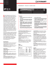
Fig. 3.5 Stereo Wiring
you may want to install supplemental cooling like a
rack-mounted blower or an air conditioner.
A “squirrel cage” blower can be installed at the bottom
of the rack so it blows outside air into the space be-
tween the door and the front of the amplifiers. This will
pressurize the “chimney” behind the door (Figure 3.4,
Option 1). The blower should not blow air into or take
air out of the space behind the amplifiers. For racks
without a front door, you can evacuate the rack by
mounting the blower at the top of the rack so air blows
out the back (Figure 3.4, Option 2). You can estimate a
rack’s required air flow by adding each unit’s maxi-
mum air flow rating. The
Studio Reference
I
and II can
each move up to 45 cubic feet (1.3 cubic meters) of air
per minute. So if you put one of each in a rack, you
would need 90 cubic feet (2.5 cubic meters) of air flow
through the rack per minute under worst-case condi-
tions (45 cubic feet + 45 cubic feet = 90 cubic feet).
Another way to increase cooling is to use air condition-
ing. It is rarely a necessity because internal fans and
rack-mounted blowers almost always provide enough
air flow for the most extreme conditions. Still, air condi-
tioning helps reduce the ambient temperature of the air
flowing through the rack. If you plan to use air condi-
tioning, refer to Section 7 for information on calculating
the hourly thermal dissipation of your system.
3.3 Wiring
Figures 3.5 through 3.7 show common ways to set up a
Studio Reference
amplifier. Input and output connec-
tors are located on the back panel. Be careful when
BLOWER
(OPTION 2)
BLOWER
(OPTION 1)
AIR
FLOW
FRONT
OF
RACK
DOOR
AIR
FLOW
EQUIPMENT
RACK
(SIDE VIEW)
Fig. 3.4 Proper Air Flow with a Rack-Mounted Blower
mounting, piles of power cords, clogged dust filters and
closed rack doors. Mount your amplifier to allow suffi-
cient air flow into the front intake, out the side exhaust
vents, and out the back of the rack. An air flow restriction
like a pile of power cords can simply be moved out of the
way. Air filters should be cleaned using the procedure in
Section 4.5. If rack doors are the problem, you can leave
them open, remove them, or install a grille. If you install
a grille, we recommend using a wire grille because per-
forated panels restrict air flow by at least 40%.
If your
ODEP
indicators still dim under demanding con-
ditions, we recommend that you check the table of
indicator states in Figure 4.2 to eliminate other condi-
tions that could be the source of the problem. If it is
clear that the amplifier does not have sufficient air flow,
STEREO MODE
Reference
STUDIO
CH-2 CH-1
PUSHPUSH
FX
MIXER
STUDIO REFERENCE
AMPLIFIER
+
–
+
–
CHANNEL 1
LOUDSPEAKER
CHANNEL 2
LOUDSPEAKER
CHANNEL 1
CHANNEL 2
CAUTION: TURN OFF AMPLIFIER
BEFORE CHANGING THIS SWITCH!
STEREO
BRIDGE
MONO
PARALLEL
MONO

Page 12
Studio Reference
II
II
I
&
IIII
IIII
II
Professional Studio Amplifiers
making connections, selecting sources and controlling
output levels. The load you save may be your own!
Crown is not responsible for damaged loads that result
from carelessness or deliberate overpowering.
CAUTION: Always disconnect the AC power and
turn the level controls down when making or break-
ing connections. This practice reduces the chance of
loud blasts that can cause loudspeaker damage.
Studio Reference
amplifiers provide three operating
modes: Stereo, Bridge-Mono and Parallel-Mono. Ste-
reo mode provides standard two-channel operation;
Bridge-Mono provides a single channel with double
the output voltage of Stereo mode; and Parallel-Mono
mode provides a single channel with double the output
current of Stereo mode. These modes can be selected
using the stereo/mono switch on the back panel. Each
mode is wired differently, so be sure to note any spe-
cial wiring requirements for the mode you will be using.
3.3.1 Stereo (Two-Channel) Operation
Stereo mode installation is very intuitive: input chan-
nel 1 feeds output channel 1, and input channel 2
feeds output channel 2. To put the amplifier into Stereo
mode, turn it off, slide the stereo/mono switch to the
center position, and properly connect the output wiring
as shown in Figure 3.5. Each output channel has two
sets of binding posts to make it easier for you to con-
nect multiple loudspeaker cables to each channel. Be
sure to observe correct loudspeaker polarity (see Fig-
ure 3.5) and be careful not to short the outputs.
CAUTION: In Stereo mode, never tie an amplifier’s
outputs together directly, and never parallel them
with the output of another amplifier. Such connec-
tions do not result in increased output power, but may
activate the protection circuitry to prevent overheating.
3.3.2 Bridge-Mono Operation
Bridge-Mono mode is used to drive loads with a total
impedance of at least 4 ohms (see Parallel-Mono if the
load is less than 4 ohms). Wiring for Bridge-Mono
mode is different from the other modes and requires
special attention. First, turn off the amplifier. Then se-
lect Bridge-Mono mode by sliding the stereo/mono
switch to the right (as you face the back panel). Both
outputs receive the channel 1 input signal, but chan-
nel 2 is inverted so it can be bridged with channel 1.
Do not use the channel 2 input or signal quality will be
Reference
STUDIO
CH-2 CH-1
PUSHPUSH
FX
STUDIO REFERENCE
AMPLIFIER
MIXER
LOUDSPEAKER
–
+
CHANNEL 1
DO NOT USE
THE CHANNEL 2
INPUTS.
DO NOT USE
THE BLACK
BINDING
POSTS.
CAUTION: TURN OFF AMPLIFIER
BEFORE CHANGING THIS SWITCH!
STEREO
BRIDGE
MONO
PARALLEL
MONO
BRIDGE-MONO MODE
Fig. 3.6 Bridge-Mono Wiring

Page 13
Studio Reference
II
II
I
&
IIII
IIII
II
Professional Studio Amplifiers
greatly degraded. Also, turn down the channel 2 level
control (fully counterclockwise).
Note: The channel 2 input and level control are not de-
feated in Bridge-Mono mode. Any signal feeding chan-
nel 2 will work against the channel 1 signal, and usually
results in distortion and inefficient operation.
Connect the load across the two red (+) binding posts
(see Figure 3.6). The positive (+) loudspeaker lead
connects to the red channel 1 binding post, and the
negative (–) or ground lead from the loudspeaker con-
nects to the red channel 2 binding post. Do not con-
nect the black binding posts (–). Also, the load must be
balanced (neither side shorted to ground).
CAUTION: Only connect balanced equipment
(meters, switches, etc.) to the Bridge-Mono output.
Both sides of the line must be isolated from the in-
put grounds or oscillations may occur.
3.3.3 Parallel-Mono Operation
Parallel-Mono mode is used to drive loads with a total
impedance of less than 4 ohms (see Bridge-Mono if the
load is 4 ohms or more). Wiring for Parallel-Mono mode
Reference
STUDIO
CH-2 CH-1
PUSHPUSH
FX
STUDIO REFERENCE
AMPLIFIER
MIXER
LOUDSPEAKER
–
+
CHANNEL 1
THE CHANNEL 2
INPUTS ARE
NOT USED
ADD A 14 GAUGE
OR LARGER
JUMPER BETWEEN
THE CHANNEL 1
AND 2 RED (+)
BINDING POSTS
CAUTION: TURN OFF AMPLIFIER
BEFORE CHANGING THIS SWITCH!
STEREO
BRIDGE
MONO
PARALLEL
MONO
PARALLEL-MONO MODE
Fig. 3.7 Parallel-Mono Wiring
is very different from the other modes and requires
special attention.
To select Parallel-Mono mode, turn off the amplifier and
slide the stereo/mono switch to the left (as you face the
back panel). Connect the input signal to channel 1 only.
The channel 2 input and level control are bypassed in
this mode, so they should not be used.
Note: It is normal for the channel 2 IOC indicator to stay
on in Parallel-Mono mode.
Connect the load to the channel 1 output as shown in
Figure 3.7. The positive (+) lead from the loudspeaker
connects to the red channel 1 binding post, and the
negative (–) or ground lead from the loudspeaker con-
nects to the black channel 1 binding post. Finally, in-
stall a jumper wire of at least 14 gauge between the
channel 1 and channel 2 red binding posts.
CAUTION: When Parallel-Mono wiring is installed,
do not attempt to operate in Stereo or Bridge-Mono
mode until the wiring is removed (especially the
jumper wire). Failure to do so will result in high dis-
tortion and excessive heating.

Page 14
Studio Reference
II
II
I
&
IIII
IIII
II
Professional Studio Amplifiers
3.3.4 Input Connection
The balanced inputs have a nominal impedance of
10 K ohms (5 K ohms unbalanced) and will accept the
line-level output of most devices. Phone jacks are pro-
vided on the back panel, while the factory-installed
P.I.P.-FX provides female XLR input connectors (see
Figure 2.2). Optional
P.I.P.
modules like the P.I.P.-BB
and the P.I.P.-FPX can provide barrier block and
phono (RCA) connectors. Various
P.I.P.s
are also avail-
able which provide a wide range of input signal pro-
cessing features (see Section 8).
Correct input wiring depends on two factors:
(1) whether the input signal is balanced or unbal-
anced, and (2) whether the signal floats or has a
ground reference. Figures 3.8 and 3.9 show the recom-
mended connection techniques for each combination
of source signal characteristics.
3
1 2
+
–
INPUT
2-wire line cord
(or battery power)
Note: If two or more channels with
the same input ground reference
are driven from the same
floating source, connect
only one shield to the
source chassis.
Floating
source
3-wire grounded line cord
(
or other
g
round connection
)
Shield not connected
at this end
Grounded
source
3
1 2
Output
+
–
+
–
Output
+
–
INPUT
Fig. 3.9 Balanced Input Wiring
The amplifier’s built-in
1
¦4-inch input phone jacks can
be wired similarly for balanced or unbalanced, floating
or ground-referenced sources. They have a standard
tip-ring-sleeve (TRS) configuration: the tip is positive
(+), the ring is negative (–) and the sleeve is ground
(see Figure 3.10). Wiring for various sources follows
the XLR wiring examples in Figures 3.8 and 3.9.
If you install a
P.I.P.
module other than the P.I.P.-FX,
P.I.P.-BB, P.I.P.-FMX or P.I.P.-FPX, do not connect in-
put signals to the phone jacks. The phone jacks are in
parallel with the output of the
P.I.P.
module, so the
source connected to the phone jacks can feed into the
P.I.P.
and generate a distortion in the output. The
phone jacks can still be used as “daisy chain” outputs
to feed the post-processed signal from the
P.I.P.
to the
input of other amplifiers.
If the amplifier will be used in Bridge-Mono or Parallel-
Mono mode, be sure to follow the instructions provided
in Sections 3.3.2 and 3.3.3. Do not use the channel 2
input in either mono mode.
+
–
SHIELD
BALANCED
+
S
HIELD
UNBALANCED
Fig. 3.10 Balanced and Unbalanced Phone Plugs
Fig. 3.8 Unbalanced Input Wiring
Twin-lead shielded cable
2-wire line cord
(or battery power)
Shield connected
to ground terminal
3-wire grounded line cord
(or other ground connection)
Shield is not
connected
at this end
Grounded
source
3-wire grounded line cord
(or other ground connection)
Input ground
terminal not used
Grounded
source
Single-conductor coax
or twisted pair
2-wire line cord
(or battery power)
Floating
source
Shield connected to both
negative (–) and ground
input terminals
+
–
INPUT
Output
Floating
source
+
3
1 2
+
–
INPUT
+
Output
3
1 2
+
–
INPUT
Output
+
3
1 2
+
–
+
Output
INPUT
3
1 2

Page 15
Studio Reference
II
II
I
&
IIII
IIII
II
Professional Studio Amplifiers
SOLVING INPUT PROBLEMS
Sometimes large subsonic (subaudible) frequencies
are present in the input signal. These can damage
loudspeakers by overloading or overheating them. To
attenuate such frequencies, place a capacitor in series
with the input signal line. The graph in Figure 3.11
shows some capacitor values and how they affect the
frequency response of a
Studio Reference
amplifier.
Use only low-leakage capacitors.
For balanced input wiring, use an example from Fig-
ure 3.13. Filters A, B and C correspond to the
unbalanced filters shown in Figure 3.12. Filter D also
incorporates the subsonic filter in Figure 3.11.
Fig. 3.13 Balanced RF Filters
Input Wiring Tips
1. Use only shielded cable. Cables with
higher density shields are better. Spiral
wrapped shield is not recommended.
2. When using unbalanced lines, keep the
cables as short as possible. Avoid cable
lengths greater than 10 feet (3 meters).
3. Do not run signal cables together with
high-level wiring such as loudspeaker wires
or AC cords. This reduces the chance of
hum or noise being induced into the input
cables.
4. Turn the entire system off before chang-
ing connections. Turn level controls down
before powering the system back up. Crown
is not liable for damage incurred when any
transducer or component is overdriven.
Tip:
The P.I.P.-FX has plenty of space on its circuit
board for the addition of input filter circuitry.
Another problem to avoid is ground loops. These are
undesired currents that flow in a grounded system and
usually cause hum in the output. A common source of
ground loop problems is the placement of input cables
parallel to power cables or near power transformers.
The magnetic field that surrounds these conductors
can induce the 50 or 60 Hz alternating current into your
input cables. To prevent this type of ground loop, it is
always a good idea to locate input cables away from
1 Hz 10 Hz 100 Hz 1 kHz 10 kHz
dB
0
–5
–10
–15
Frequency
0
.
0
4
7
µ
f
0
.
1
µ
f
0
.
4
7
µ
f
1
.
0
µ
f
4
.
7
µ
f
Another problem to avoid is large levels of radio fre-
quencies or RF in the input signal. Although high RF
levels may not pose a threat to the amplifier, they can
burn out tweeters or other loads that are sensitive to
high frequencies. Extremely high RF levels can also
cause your amplifier to prematurely activate its protec-
tion circuitry, resulting in inefficient operation. RF can
be introduced into a signal by local radio stations and
from the bias signal of many tape recorders. To pre-
vent high levels of input RF, install an appropriate
low-pass filter in series with the input signal. Some ex-
amples of unbalanced wiring for low-pass filters are
shown in Figure 3.12.
Fig. 3.12 Unbalanced RF Filters
Fig. 3.11 Subsonic Filter Capacitors
4 kHz 10 kHz 40 kHz 100 kHz
Frequency
dB
0
–10
–20
A
B
C
6 dB/octave
12 dB/octave
To
Amp
GND
To
Amp
GND
To
Amp
GND
Source
910 ohms
.0056
µ f
.015
f
µ
.018
fµ
3.9 mH
5 mH
600 ohm
Source
R
600 ohm
Source
R
A
C
B
Note: A low source impedance (R) can be
increased to 600 ohms with an appropriate resistor.
+
–
Balanced In
470 ohms
.0056
µ
f
.015
f
µ
.018
f
µ
1.8 mH
2.5 mH
A
C
B
.015
f
µ
1.8 mH
D
Balanced Out
+
–
470 ohms
1.8 mH
2.5 mH
1.8 mH
+
–
Balanced In
Balanced Out
+
–
+
–
Balanced In
Balanced Out
+
–
+
–
Balanced In
Balanced Out
+
–
0.47 Film
0.47 Film

Page 16
Studio Reference
II
II
I
&
IIII
IIII
II
Professional Studio Amplifiers
power cables and power transformers. We also recom-
mend using shielded or twisted pair wire. With loose
wires, use tie-wraps to bundle together each pair of in-
put wires. This helps reduce magnetically-induced
current by minimizing the cross-sectional area be-
tween conductors that could bisect the magnetic field.
Ground loops often occur when the input and output
grounds are tied together. DO NOT CONNECT THE
INPUT AND OUTPUT GROUNDS TOGETHER. Tying
the grounds together can also cause feedback oscil-
lation from the load current flowing in the loop. To
avoid this problem, use proper grounding, isolate the
inputs, and isolate other common AC devices. When
using the input phone jacks, the signal grounds can be
isolated from the AC mains ground with the ground lift
switch located on the amplifier’s back panel (see Fig-
ure 2.2 and Section 4.4).
3.3.5 Output Connection
Consider the rated power-handling capacity of your
load before connecting it to the amplifier. Crown is not
liable for damage incurred at any time due to overpow-
ering. Fusing loudspeaker lines is highly recom-
mended (see Section 3.3.6). Also, please pay close
attention to Section 4.1,
Precautions
.
You should always install loudspeaker cables of suffi-
cient gauge (wire thickness) for the length used. The
resistance introduced by inadequate output wiring will
reduce the amplifier’s power to and motion control of
the loudspeakers. The latter problem occurs because
Use Good Connectors
1. Male connectors on loudspeaker cables
should not be exposed to prevent possible
short circuits.
2. Connectors which might accidentally
cause the two channels to be tied together
when making and breaking connections
should not be used. (A common example is
the standard three-wire stereo phone plug.)
3. Connectors which can be plugged into
AC power receptacles should never be used.
4. Connectors having low current-carrying
capacity should not be used.
5. Connectors having any tendency to short
should never be used.
the damping factor decreases as the cable resistance
increases. This is very important because the ampli-
fier’s excellent damping factor can be easily negated
by using insufficient cable.
Use the nomograph in Figure 3.14 and the procedure
that follows to find the recommended wire gauge
(AWG or American Wire Gauge) for your system.
Fig. 3.14 Wire Size Nomograph
40
30
20
15
10
9
8
7
6
5
4
3
2
1
2
5
10
20
50
100
.04
.06
.1
.2
.4
.6
1
2
4
6
10
20
40
5
10
20
50
1
2
100
200
500
1000
2000
5000
8000
5000
1000
500
100
50
10
5
1
.5
.1
.05
.01
#28
#26
#24
#22
#20
#18
#16
#14
#12
#10
#8
#6
#4
#2
#0
#00
#0000
R
LOAD
RESISTANCE
(ohms)
L
R
R
DAMPING
FACTOR
L
S
R
SOURCE
RESISTANCE
(ohms)
S
2-COND.
CABLE
(feet)
COPPER
WIRE
(AWG)
(ohms/1000 ft.)
Example Shown:
R = 8 ohms; R = 0.016 ohms or D.F. = 500;
Cable Length = 10 ft.; answer: #8 wire
L
S
1
0.5
200
500
1,000
2,000
20,000
5,000
10,000
.01
.001
.02
.004
.006
.002
.0004
.0006
.0002
0.6
0.7
0.8
1.5
0.9

Page 17
Studio Reference
II
II
I
&
IIII
IIII
II
Professional Studio Amplifiers
amplifiers share a common cable tray or jacket,
use tie-wraps to bundle individual conductors so
the wires for each loudspeaker are kept close
together. (Do not bundle wires from different
amplifiers.) This reduces the chance of conduc-
tors acting like antennas to transmit or receive the
high frequencies that can cause oscillation.
2. Avoid using shielded loudspeaker cable.
3. Never tie together input and output grounds.
4. Never tie together the output of different amplifiers.
5. Keep output cables separated from input cables.
6. Install a low-pass filter in series with each input
(see Section 3.3.4).
7. Install the input wiring according to the instruc-
tions in Section 3.3.4.
Another problem to avoid is the presence of large
subsonic currents when primarily inductive loads are
used. Examples of inductive loads are 70-volt step-up
transformers and electrostatic loudspeakers.
Inductive loads can appear as a short circuit at low fre-
quencies. This can cause the amplifier to produce
large low-frequency currents and activate its protec-
tion circuitry. Always take the precaution of installing a
high-pass filter in series with the amplifier’s input when
inductive loads are used. A three-pole, 18 dB per oc-
tave filter with a –3 dB frequency of 50 Hz is recom-
mended (some applications may benefit from an even
higher –3 dB frequency). Such a filter is described with
the subsonic frequency problems in Section 3.3.4.
Another way to protect inductive loads from large low-
frequency currents and prevent the amplifier from pre-
maturely activating its protective systems is to parallel
a 590 to 708 mF nonpolarized motor start capacitor and
4-ohm, 20-watt resistor in series with the amplifier out-
put and the positive (+) transformer lead. This circuit is
shown in Figure 3.15. It uses components that are
1. For loads connected in parallel, use the equation that
follows to calculate each channel’s total load resistance.
Substitute the rated impedance of the connected loud-
speakers for the Zs in the equation. When finished, mark
your answer on the nomograph’s “Load Resistance” line.
Total Load Resistance in Ohms = (
1
¦
Z
1
+
1
¦
Z
2
+
1
¦
Z
3
…)
–1
2. Select an acceptable damping factor and mark it on
the “Damping Factor” line. Your amplifier can provide an
phenomenal damping factor of 20,000 from 10 to 200 Hz
in Stereo mode with an 8 ohm load. In contrast, most
other amplifiers have a damping factor rating of 200 or
less. Higher damping factors yield lower distortion and
greater motion control over the loudspeakers. To give you
a basis for comparison, effective damping factors for
commercial applications typically run between 50 and
100. Higher damping factors may be desirable for live
sound, but long cable lengths often limit the highest
damping factor that can be achieved practically. (Under
these circumstances, Crown’s
IQ System
is often used so
amplifiers can be easily monitored and controlled when
they are located very near the loudspeakers.) In record-
ing studios and home hi-fi, a damping factor of 500 or
more is very desirable.
3. Draw a line through the two points with a pencil, and
continue until it intersects the “Source Resistance” line.
4. On the “2-Cond. Cable” line, mark the length of the
cable run.
5. Draw a pencil line from the mark on the “Source Resis-
tance” line through the mark on the “2-Cond. Cable” line,
and on to intersect the “Annealed Copper Wire” line.
6. The required wire gauge for the selected wire length and
damping factor is the value on the “Annealed Copper Wire”
line.
Note: Wire size increases as the AWG gets smaller
.
7. If the size of the cable exceeds what you want to use,
(1) find a way to use shorter cables, like using the
IQ Sys-
tem
, (2) settle for a lower damping factor, or (3) use more
than one cable for each line. Options 1 and 2 will require the
substitution of new values for cable length or damping factor
in the nomograph. For option 3, estimate the effective wire
gauge by subtracting 3 from the apparent wire gauge every
time the number of conductors of equal gauge is doubled.
So, if #10 wire is too large, two #13 wires can be substituted,
or four #16 wires can be used for the same effect.
SOLVING OUTPUT PROBLEMS
High frequency oscillations can cause your amplifier
to prematurely activate its protection circuitry. The ef-
fects of this problem are similar to the effects of the RF
problem described in Section 3.3.4. To prevent high-
frequency oscillations, follow these guidelines:
1. When using long cable runs, or when different
Fig. 3.15 Inductive Load (Transformer) Network
4-ohm, 20-watt
Resistor
590 to 708 µf Capacitor
120 VAC, N.P.
+
–
Inductive
Load
+
–
From
Amplifier
Output

Page 18
Studio Reference
II
II
I
&
IIII
IIII
II
Professional Studio Amplifiers
available from most electrical supply stores.
3.3.6 Additional Load Protection
Studio Reference
amplifiers can deliver very high
power levels, so it’s a good idea to add protection for
your loudspeakers if it is not built-in. Loudspeakers are
subject to thermal damage from sustained overpower-
ing and mechanical damage from large transient volt-
ages. In both cases, fuses may be used to protect your
loudspeakers, or you may opt for the convenience of a
P.I.P.
module that provides similar protection.
Thermal protection and voltage protection require dif-
ferent types of fuses. Slow-blow fuses are used to pre-
vent thermal damage because they respond to thermal
conditions like a loudspeaker. High-speed instrument
fuses like the Littlefuse 361000 series are used to pro-
tect loudspeakers from transient voltages. The nomo-
graph in Figure 3.16 can be used to select the correct
fuse for thermal or voltage protection.
There are two common ways to install the fuses. One
approach is to put a single fuse in series with each out-
put. This is easy because there is only one fuse per
channel to install. But if the fuse blows, power is re-
moved to all of the connected loads.
A better approach is to fuse each driver independently.
This allows you to apply the most appropriate protec-
tion for the type of driver being used. In general, low-
frequency drivers (woofers) are most susceptible to
thermal damage and high-frequency drivers (tweeters)
are usually damaged by large transient voltages. This
means that your loudspeakers will tend to have better
protection when the woofers are protected by slow-
blow fuses and high-frequency drivers are protected
by high-speed instrument fuses.
Depending on the application, you may want to use a
specialized
P.I.P.
module to protect your loudspeak-
ers. Again, some modules are more appropriate for
long-term thermal protection, while others are more ap-
propriate for protection against transients. A
Smart Amp
™
IQ-P.I.P. module is most commonly used
for long-term loudspeaker thermal protection. Each
Smart Amp
channel provides an independent “smooth
output limiter” that controls average output levels over
time while it allows transients to pass.
Most of the other
P.I.P.
modules that provide signal-
driven compression can be used to prevent loud-
speaker damage from transient voltage. These
modules include the P.I.P.-AMCb, P.I.P.-EDCb and
P.I.P.-PA. While the P.I.P.-EDCb is most commonly
used for general loudspeaker protection, the
P.I.P.-AMCb is very popular in systems that require a
high-quality crossover, and the P.I.P.-PA is the proces-
sor of choice for applications that require a microphone
and line level input for each channel. And finally, the
Smart Amp
IQ-P.I.P.-DP provides both an input com-
pressor for transient protection and a smooth output
limiter for long-term thermal protection. For more infor-
mation on
P.I.P.
modules, see Section 8.
3.4 AC Mains Power
All
Studio Reference
amplifiers are shipped with an
appropriate line cord and plug. The 120 VAC, 60 Hz
North American
Studio Reference
I has a special
TT30P plug and includes a matching receptacle. Al-
ways use an isolated power receptacle whenever pos-
sible with adequate voltage and current. Excessive line
voltages 10% or higher above the rated voltage will
cause the amplifier to activate its standby mode (see
Section 4.3.2). For example, do not exceed a 132 VAC
with models rated for 120 VAC operation.
Unless otherwise noted, all specifications in this
manual were measured using 120 VAC, 60 Hz power
mains with voltage accurate to within 0.5% and THD of
less than 1.0% under all test conditions. Performance
variations can occur at other AC mains voltages and
line frequencies. Line regulation problems will directly
affect the output power available from the amplifier.
Fig. 3.16 Loudspeaker Fuse Nomograph
1.0
1.2
1.4
1.6
2.5
3
4
5
6
7
8
9
10
12
14
16
20
25
30
20
15
10
8
6
5
4
3
2
1.5
1
.8
.6
.5
.4
.3
.2
.15
.1
.08
3000
2000
1500
1000
800
600
400
300
200
150
100
80
60
40
30
20
15
10
8
6
4
3
2
1.5
1
LOUDSPEAKER IMPEDANCE
(ohms)
FUSE
(amps)
LOUDSPEAKER RATING
PEAK MUSIC POWER
(watts)
(Typically 4 times the continuous average power)
Answer: Fuse = 1.5 A
2
40
Example:
Impedance = 8 ohms.
Peak Power = 75 W

Page 19
Studio Reference
II
II
I
&
IIII
IIII
II
Professional Studio Amplifiers
4 Operation
4.1 Precautions
Although your amplifier is protected from internal and
external faults, you should still take the following pre-
cautions for optimum performance and safety:
1. Improper wiring for the Stereo, Bridge-Mono or
Parallel-Mono modes can result in serious operat-
ing difficulties (see Sections 3.3.1 through 3.3.3).
2. When driving an inductive load like an electrostatic
loudspeaker, use a high-pass filter or protective
network to prevent premature activation of the
amplifier’s protection circuitry (see Section 3.3.4).
3. WARNING: Do not change the position of the ste-
reo/mono switch unless the amplifier is first turned
off.
4. CAUTION: In Parallel-Mono mode, a jumper must
be installed between the channel 1 and 2 red (+)
binding post outputs. Be sure to remove this jumper
for Stereo or Bridge-Mono modes, otherwise high
distortion and excessive heating will occur. Check
the stereo/mono switch on the back panel for
proper position.
5. Turn off the amplifier and unplug it from the AC
mains before removing the amplifier’s
P.I.P.
mod-
ule or dust filter.
6. Use care when making connections, selecting sig-
nal sources and controlling the output level. The
load you save may be your own!
7. Do not short the ground lead of an output cable to
the input signal ground. This will form a ground
loop and may cause oscillations.
8. Operate the amplifier from AC mains of not more
than 10% above or below the selected line voltage
and only at the rated line frequencies.
9. Never connect the output to a power supply output,
battery or power main. Such connections may re-
sult in electrical shock.
10. Tampering with the circuitry by unqualified person-
nel, or making unauthorized circuit changes may
be hazardous and invalidates all agency listings.
Remember: Crown is not liable for damage that results
from overdriving other system components.
4.2 Indicators
The front panel has several helpful indicators. The en-
able indicator is provided to show the amplifier has
been turned on (or enabled) and that its low-voltage
Fig. 4.1 Indicators
power supply and on-demand forced air cooling sys-
tem are working. It does not indicate the status of the
high-voltage power supplies. For example, the enable
indicator will stay on in the improbable event that one
or both channels overheat causing an internal shut
down of the high
voltage supplies.
The green
ODEP
indicators confirm the normal opera-
tion of Crown’s patented Output Device Emulation Pro-
tection circuitry. During normal operation, they glow
brightly to confirm the presence of reserve thermody-
namic energy. They dim proportionally as the energy
reserve decreases. In the rare event that there is no
reserve, the indicators will turn off and
ODEP
will pro-
portionally limit the drive level of the output stages so
the amplifier can continue safe operation even when
the operating conditions are severe. (For a more de-
tailed description of
ODEP
, see Section 4.3.1.)
A channel’s
ODEP
indicator also turns off if its high-
voltage power supply is put in “standby” mode or the
amplifier’s circuit breaker is tripped. The standby
mode is activated if DC or heavy common-mode cur-
rent is detected in the output, if the transformer thermal
protection system is activated, if a
P.I.P.
like the
Smart
Amp
IQ-P.I.P. is used to shut down a high-voltage sup-
ply, or if excessive AC mains voltage is detected. For
more information see Section 4.3 and the table in Fig-
ure 4.2.
The yellow
IOC
indicators act as sensitive distortion
meters to provide
proof of distortion-free performance
.
The
IOC
(Input/Output Comparator) circuitry compares
the incoming signal’s waveform to that of the output.
Any difference between the two is distortion. The
IOC
indicators flash if there is a difference of 0.05% or
more. The
IOC
indicators also show input overload by
flashing brightly with a half-second hold delay. It is nor-
mal for them to light momentarily when the amplifier is
first turned on.
Note: The channel 2 IOC indicator will
stay on in Parallel-Mono mode.
Also, an IOC indicator
will stay on in abnormal situations where a high-voltage
power supply is temporarily put in standby mode.

Page 20
Studio Reference
II
II
I
&
IIII
IIII
II
Professional Studio Amplifiers
As dynamic range meters they show each channel’s
ratio of peak-to-average power in dB. The dynamic
range may be low for sources like AM/FM radio or low-
quality recordings. Other sources like live music or
high-quality recordings may be much higher. As out-
put level meters they show how high the output levels
are in dB relative to full power. At 0 dB, the unit is deliv-
ering full standard 1 kHz power (see Section 6).
4.3 Protection Systems
Studio Reference
amplifiers provide extensive protec-
tion and diagnostics capabilities. Protection systems
include
ODEP
, standby mode, an AC circuit breaker
The green signal presence indicators flash synchro-
nously with the amplifier’s output signal. The signal de-
tector is connected to the signal path after the input
gain stages and level controls, so a flashing indicator
tells you that there is audio in and out of the amplifier.
Note: The signal presence indicators may not report
signal presence if the output signal level is too low.
The dynamic range /level meters are five-segment
output meters that can be set to monitor either the dy-
namic range or the level of the output signal. They are
factory-set to show dynamic range. A switch located
behind the front panel is used to select the meter dis-
play mode (see Section 4.4 for complete instructions).
Fig. 4.2 Studio Reference Indicator States
There is no power to the amplifier. Possible reasons: (1) The amplifier’s enable switch is off. (2) The
amplifier is not plugged into the power receptacle. (3) The AC mains circuit breaker has been tripped.
(4) The amplifier’s circuit breaker has been tripped.
Indicator Status Amplifier Condition
Normal operation for a channel with NO output. Possible reasons: (1) There is no input signal.
(2) The input signal level is very low. (3) The channel’s level control is turned down.
Normal operation for a channel with audio output. The ODEP indicator will remain at full intensity
to show that there is reserve thermal-dynamic energy and the signal presence indicator will flash to
show that there is audio output.
The channel’s output is exceeding 0.05% distortion. The input signal level is too high, and IOC is
reporting either an input overload or output clipping.
The amplifier is in standby mode. Possible reasons: (1) The amplifier has just been turned on and
is still in the four second turn-on delay. (2) A P.I.P. module such as an IQ-P.I.P. has turned off the
channel’s high-voltage supply. (3) The DC/ low-frequency protection circuitry has been activated.
(4) The fault protection circuitry has been activated. (5) The transformer thermal protection circuitry
has been activated. (6) The overvoltage protection circuitry has been activated.
ODEP limiting has been activated. Possible reasons: (1) The amplifier’s air filter is blocked and needs
to be cleaned. (2) There is insufficient cooling because of inadequate air flow or air that is too hot.
(3) The load impedance for the channel is too low because the output is shorted or the amplifier is
driving too many loudspeakers for the selected stereo/mono mode. (4) The amplifier channel is
continuously being driven to very high output levels.
ODEP limiting is about to begin or has just ended. Possible reasons: (1) The amplifier’s air filter is
blocked and needs to be cleaned. (2) There is insufficient cooling because of inadequate air flow or air
that is too hot. (3) The load impedance for the channel is too low because the output is shorted or the
amplifier is driving too many loudspeakers for the selected stereo/mono mode. (4) The amplifier
channel is continuously being driven to very high output levels.
OR
Channel 2 only: The amplifier is in Parallel-Mono mode and has output. The channel 2 IOC indi-
cator always turns on when the amplifier’s stereo/mono switch is moved to the Parallel-Mono position.
IOCODEP SIGNAL
OFF OFF OFF
IOCODEP SIGNAL
ON OFF OFF
IOCODEP SIGNAL
ON OFF Active
Channel 2 only: The amplifier is in Parallel-Mono mode with no output. The channel 2 IOC indi-
cator always turns on when the amplifier’s stereo/mono switch is moved to the Parallel-Mono position.
IOCODEP SIGNAL
ON ON OFF
IOCODEP SIGNAL
ON ON Active
IOCODEP SIGNAL
OFF ON OFF
IOCODEP SIGNAL
OFF OFF Active
IOCODEP SIGNAL
OFF ON Active
/