Optimus NX-100 User manual

Category
Musical Equipment
Type
User manual

This manual is also suitable for

Optimus NX-100 is a network audio adapter that transmits high-quality audio signals and control data over IP networks like LAN or the Internet. With minimal latency, it allows for real-time transmission. The device supports two-way audio signal transmission, enabling communication between multiple locations. It's multicast-capable, allowing simultaneous transmission to multiple destinations, up to 64 locations with multicast or 4 with unicast.

Optimus NX-100 is a network audio adapter that transmits high-quality audio signals and control data over IP networks like LAN or the Internet. With minimal latency, it allows for real-time transmission. The device supports two-way audio signal transmission, enabling communication between multiple locations. It's multicast-capable, allowing simultaneous transmission to multiple destinations, up to 64 locations with multicast or 4 with unicast.

The NX-100 Network Audio Adapter can transmit high-quality audio signals
and such control data as serial data over IP networks, such as LAN or
Internet, in real time.
It is especially useful when transmitting audio signals to remote locations, as
Internet use keeps running costs lower than the use of dedicated lines.
With the use of an optional rack-mounting bracket, it can be mounted in an
EIA Standard rack (1 unit size).
GENERAL DESCRIPTION
General Description
1
If there is no network delay, audio signals have only a minimal millisecond
delay.
Control data including contact and serial data can also be transmitted
along with the audio signals.
Two-way audio signal transmission is possible with a single
NX-100 unit as every unit is equipped with an audio input and output.
The multicast-capable NX-100 allows simultaneous transmission of audio
signals to be made to multiple locations depending on transmission
method:
Unicast — up to 4 locations,
Multicast — up to 64 locations.
No audio signal degradation or loss, even when transmitting over crowded
networks such as the internet.
Greater data reliability using IP networks with the protocol's ability to prevent
data problems during transmission.
The NX-100's contact input can initiate and terminate audio transmissions
without having to use dedicated control equipment such as a PC.
Hardware use ensures operational reliability over software only driven
applications.
Using IP to transmit audio signals over the internet allows low cost operation
rather than dedicated lines.
The NX-100 is equipped with a DC input to allow operation on AC as well as
DC.
Software-driven operational menus enhance ease of use.
FEATURES
Features
2
NOMENCLATURE & FUNCTION
3
Network Audio Adapter NX-100
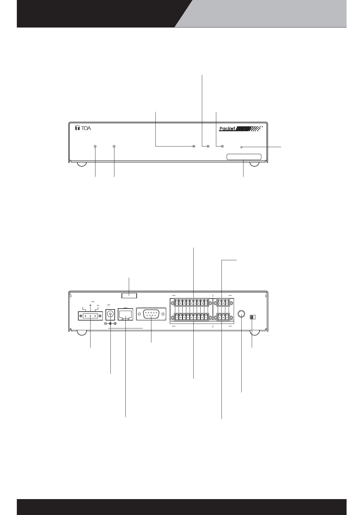
[Front]
[Rear]
LNK/ACT FD/COL STATUS ERROR RUN RESET
00-05-F9-FF-80-81
NETWORK AUDIO ADAPTER NX-100
MIC
LINE
VOLUME
INPUT
24V
DC INPUT
AUDIO OUTPUT
AC ADAPTER
FG
76
76
AUDIO INPUT
8C54321
C854321
CONTACT OUTPUT
CONTACT INPUT
RS-232C
24V 200mA
200mA
DC INPUT
10/100M
HCE
HCE
LNK/ACT Indicator (Green)
Lights when the unit is
connected to a network.
Flashes while the unit is
transmitting or receiving data.
FD/COL Indicator (Yellow)
Remains lit while the network is in
full-duplex communications mode.
Flashes whenever data collision is
detected.
Status Indicator (Yellow)
Remains lit during broadcasts.
Flashes while the unit is writing data into the
internal storage medium (flash memory).
Error Indicator (Red)
Lights if an error is detected during
transmission, etc.
Run Indicator (Green)
Remains lit during normal operation.
Flashes at 2-second intervals when
a failure is detected.
Reset Button
Restarts the unit when
pressed.
MAC Address
The unit's MAC address consists of
12 hyphenated alphanumeric characters.
Cord Clamp
Pinches and securely holds the AC adapter
cord to prevent its plug from detaching.
Control Output Terminal [CONTACT OUTPUT]
An open collector output (Withstand voltage: 30 V
DC, Control current: 50 mA maximum).
Audio Output Terminal
[AUDIO OUTPUT]
A 0 dB/600 balanced output.
Line level audio signal output.
H: Hot C: Cold E: Ground (shield)
DC Power Input Terminal
[DC INPUT]
A 24 V DC input.
Power Input Terminal
[AC ADAPTER]
Connect the AC adapter*
to this terminal.
* Use the AD-246 (optional) or its equivalent.
Network Connection Terminal [10/100M]
Connects to 10/100 Base-T networks.
(RJ-45 Ethernet jack)
RS-232C
Terminal
A 9-pin D-sub
connector (male).
Control Input Terminal
[CONTACT INPUT]
A no-voltage "make"
contact input
(Short circuit current: 10 mA,
Open voltage: 12 V).
Audio Input Terminal [AUDIO INPUT]
A -58 to 0 dB/2 k balanced input.
Microphone or line level audio signals can be
connected to this terminal.
H: Hot C: Cold E: Ground (shield)
Input Volume Control [INPUT VOLUME]
Adjusts the audio input level. Set this control
to eliminate distortion in the input signal.
Input Level Selection Switch
[LINE/MIC]
Set this switch to the MIC (right side)
position when using a microphone, and
to the LINE (left side) for other inputs.
(Factory-preset to the LINE position.)
APPLICATION EXAMPLE-1 APPLICATION EXAMPLE-1
Passenger Handling System for
Unattended Railway Stations
4
-1-1
•••
Line
Unattended Station A (172.16.0.2/16)
•••
Line
Control Office (172.16.0.1/16)
Unattended Station B (172.16.0.3/16)
EV-20R
Message 1 = On-premises standard
message
Example:
“To make inquiries, please
use the communication panel.”
Message 2 = “Calling up” message
Example: “Please wait a moment.”
C-in 1,2ch
C-out 5ch
NX-100
NX-100
C-out 1-4ch
1.Play1
2.Play2
3.STOP
EV-20R
Audio in
C-in 1,2ch
C-out 5ch
NX-100
C-out 1-4ch
1.Play1
2.Play2
3.STOP
EV-20R
Audio in
C-out 1,2ch
C-in 1-8ch
LAN/WAN
(guaranteed
bandwidth
recommended)
Operating switch box
CH 1: Real-time communication with the
communication panel at Station A
CH 2: Real-time communication with the
communication panel at Station B
CH 3: Announcement is sent to the speaker
at Station A through a mic.
CH 4: Announcement is sent to the speaker
at Station B through a mic.
CH 5:
Message 1 is sent to the speaker at Station A
CH 6:
Message 1 is sent to the speaker at Station B
CH 7:
Stop the auto-annauncement at Station A
CH 8:
Stop the auto-annauncement at Station B
Powered Speaker
Microphone
Operating switch box
“Calling up” indicator LED
Calling up Station A
Calling up Station B
On-premises
loudspeaker
Amplifier
Mixer
Communications panel
(equipped with
“Call in Progress” indicator)
Remote control
power on/off
On-premises
loudspeaker
Amplifier
Mixer
Communications panel
(equipped with
“Call in Progress” indicator)
Remote control
power on/off
Filling the need to provide useful communication for passengers at unattended stations, this system allows
automated announcements such as train times and messages for two unattended stations from a remote
location. It also makes it possible for a passenger waiting at the station to use the system’s communication
panel for realtime communication with railway personnel for inquiries as well as emergencies.
APPLICATION EXAMPLE-1 UNIT SCAN-1
Passenger Handling System for
Unattended Railway Stations
4-1-2
Click
“Unit Scan
(Network Setting)”
Click
(Scanning start)
APPLICATION EXAMPLE-1 Network Setting-1
Passenger Handling System for
Unattended Railway Stations
4-1-3
Change
IP address
Scanning Complete
Change
Unit name
Change Subnet mask
and Default gateway
as required.
(There is no in
a change by
this example)
APPLICATION EXAMPLE-1 Network Setting-2
Passenger Handling System for
Unattended Railway Stations
4
-1-4
2) Click “File”
3) Select “Save in
setting file format”
1) Confirm changed data
1) Click
(Change settings)
2) Check
all units
APPLICATION EXAMPLE-1 SYSTEM SETTING-1
Passenger Handling System for
Unattended Railway Stations
4-1-5
1) Click
“Broadcast Spec”
2) Change packet size
from 64 to 128
3) Confirm that
there is not
“Two-ways streaming”
in “Not possible with
this setting”
Click “System Setting”
Select “office”
Broadcast Spec Setting for Office (1)
Broadcast Spec Setting for Office (2)
APPLICATION EXAMPLE-1 SYSTEM SETTING-2
Passenger Handling System for
Unattended Railway Stations
4-1-6
1) Click
“Broadcast Pattern”
2) Click
“Add”
3) Input name
4) Click
“A station”
1) Click
“Add”
3) Click
“B station”
2) Input name
Broadcast Pattern Setting for Office (1)
Broadcast Pattern Setting for Office (2)
APPLICATION EXAMPLE-1 SYSTEM SETTING-3
Passenger Handling System for
Unattended Railway Stations
4
-1-7
1) Click
“Add”
4) Click
“A station”
2) Input name
3) Change
“Direction” to
“Reception”
1) Click
“Add”
4) Click
“B station”
2) Input name
3) Change
“Direction” to
“Reception”
Broadcast Pattern Setting for Office (3)
Broadcast Pattern Setting for Office (4)
APPLICATION EXAMPLE-1 SYSTEM SETTING-4
Passenger Handling System for
Unattended Railway Stations
4
-1-8
Contact Input Setting for Office (1)
Contact Input Setting for Office (2)
1) Click
“Contact”
2) Click “Input 1”
3) Crick
“Enable contact”
4) Click
“A station mic”
5) Click
“A station panel”
6) Click
“A station”
7) Click “5”
1) Click “Input 1”
2) Click
“Enable contact”
3) Click
“A station mic”
4) Click
“A station panel”
5) Click
“B station”
6) Click “5”
APPLICATION EXAMPLE-1 SYSTEM SETTING-5
Passenger Handling System for
Unattended Railway Stations
4-1-9
Contact Input Setting for Office (3)
1) Click “Input 3”
2) Click
“Enable contact”
3) Click
“A station mic”
5) Click
“A station”
6) Click “4”
Contact Input Setting for Office (4)
1) Click “Input 4”
2) Click
“Enable contact”
3) Click
“B station mic”
4) Click
“B station”
5) Click “4”
APPLICATION EXAMPLE-1 SYSTEM SETTING-6
Passenger Handling System for
Unattended Railway Stations
4
-1-10
Contact Input Setting for Office (5)
1) Click “Input 5”
2) Click
“Enable contact”
3) Click
“A station”
4) Click
“1” and “4”
Contact Input Setting for Office (6)
1) Click “Input 6”
2) Click
“Enable contact”
4) Click
“1” and “4”
3) Click
“B station”
APPLICATION EXAMPLE-1 SYSTEM SETTING-7
Passenger Handling System for
Unattended Railway Stations
4-1-11
Contact Input Setting for Office (7)
1) Click “Input 7”
2) Click
“Enable contact”
3) Click
“office” and
“A station”
4) Click “3”
5) Crick “3”
Contact Input Setting for Office (8)
1) Click “Input 6”
2) Click
“Enable contact”
4) Click
“4”
6) Click
“3”
5) Click
“B station”
3) Click
“office”
APPLICATION EXAMPLE-1 SYSTEM SETTING-8
Passenger Handling System for
Unattended Railway Stations
4-1-12
Contact Input Setting for A Station (1)
2) Click “Input 1”
3) Click
“Enable contact”
5) Click
“1”
7) Click
“2”
4) Click
“office”
6) Click
“A station”
1) Select
“A station”
Contact Input Setting for A Station (2)
1) Click “Input 2”
2) Click
“Enable contact”
4) Click
“3”
6) Click
“3”
3) Click
“office”
5) Click
“A station”
APPLICATION EXAMPLE-1 SYSTEM SETTING-9
Passenger Handling System for
Unattended Railway Stations
4
-1-13
Contact Input Setting for B Station (1)
2) Click “Input 1”
3) Click
“Enable contact”
5) Click
“2”
7) Click
“2”
4) Click
“office”
6) Click
“B station”
1) Select
“A station”
Contact Input Setting for B Station (2)
1) Click “Input 2”
2) Click
“Enable contact”
4) Click
“4”
6) Crick
“3”
3) Click
“office”
5) Click
“B station”
APPLICATION EXAMPLE-1 SYSTEM SETTING-10
Passenger Handling System for
Unattended Railway Stations
4-1-14
Save
1) Click “File”
2) Select
“Save to file”
APPLICATION EXAMPLE-2 APPLICATION EXAMPLE 2
Transaction Information Transmission System
for Securities Trading Companies
4
-2-1
NX-100
NX-100
NX-100
Multicast Address for Transmission
(225.1.1.1)
(225.1.1.1)
Multicast Address for Transmission
(225.1.1.1)
Securities Exchange
PCs operated by
the Tokyo Head Office
(10.0.0.128/8)
NX-100NX-100
NX-100
NX-100
NX-100 NX-100
Dedicated
WAN Line
(guaranteed
bandwidth
recommended)
Tokyo Head Office (10.0.0.1/8)
Okinawa Office (10.0.1.9/8)
Fukuoka Office (10.0.1.8/8)
Takamatsu Office (10.0.1.7/8)
Osaka Office (10.0.1.6/8)Nagoya Office (10.0.1.5/8)Yokohama Office (10.0.1.4/8)
Sendai Office (10.0.1.3/8)
Sapporo Office (10.0.1.2/8)
Powered Speaker
Microphone
Mixer
Mobile phone
Powered
Speaker
Microphone
Powered
Speaker
Microphone
Powered
Speaker
Microphone
Powered
Speaker
Microphone
Powered
Speaker
Microphone
Powered
Speaker
Microphone
Powered
Speaker
Microphone
Powered
Speaker
Microphone
Businesses such as these require cost-effective and versatile communications systems that
facilitate realtime communication between various offices and a head office. TOA systems
provide the communication reliability that these companies absolutely require and make it easy
for all offices to receive important announcements and messages at the same time.
APPLICATION EXAMPLE-2 SYSTEM SETTING-1
Transaction Information Transmission System
for Securities Trading Companies
4
-2-2
Reception Pattern Setting for All Call
1) Click “Broadcast Pattern”
2) Click “Add”
3) Input name
4) Check all items
Initial Screen
Broadcast Spec Setting
2) Click
“Broadcast Spec”
3) Select “128”
1) Select
“TOKYO”
Set IP address
and name
beforehand
4) Confirm that there is not
“Two-ways streaming”
in “Not possible
with this setting”
  • Page 1 1
  • Page 2 2
  • Page 3 3
  • Page 4 4
  • Page 5 5
  • Page 6 6
  • Page 7 7
  • Page 8 8
  • Page 9 9
  • Page 10 10
  • Page 11 11
  • Page 12 12
  • Page 13 13
  • Page 14 14
  • Page 15 15
  • Page 16 16
  • Page 17 17
  • Page 18 18
  • Page 19 19
  • Page 20 20
  • Page 21 21
  • Page 22 22
  • Page 23 23
  • Page 24 24
  • Page 25 25
  • Page 26 26
  • Page 27 27
  • Page 28 28
  • Page 29 29
  • Page 30 30
  • Page 31 31
  • Page 32 32
  • Page 33 33
  • Page 34 34
  • Page 35 35
  • Page 36 36
  • Page 37 37
  • Page 38 38
  • Page 39 39
  • Page 40 40
  • Page 41 41
  • Page 42 42
  • Page 43 43
  • Page 44 44
  • Page 45 45
  • Page 46 46
  • Page 47 47
  • Page 48 48
  • Page 49 49
  • Page 50 50
  • Page 51 51
  • Page 52 52
  • Page 53 53
  • Page 54 54
  • Page 55 55
  • Page 56 56
  • Page 57 57
  • Page 58 58
  • Page 59 59
  • Page 60 60
  • Page 61 61
  • Page 62 62
  • Page 63 63
  • Page 64 64
  • Page 65 65
  • Page 66 66
  • Page 67 67
  • Page 68 68
  • Page 69 69
  • Page 70 70

Optimus NX-100 User manual

Category
Musical Equipment
Type
User manual
This manual is also suitable for

Optimus NX-100 is a network audio adapter that transmits high-quality audio signals and control data over IP networks like LAN or the Internet. With minimal latency, it allows for real-time transmission. The device supports two-way audio signal transmission, enabling communication between multiple locations. It's multicast-capable, allowing simultaneous transmission to multiple destinations, up to 64 locations with multicast or 4 with unicast.

Ask a question and I''ll find the answer in the document

Finding information in a document is now easier with AI