
installation Instructions
for Heavy duty
Please real ALL installations before installing. Two
or more people are recommended to install this
product. If a new electrical outlet is required, have
the outlet installed by a qualified electrician before
installing unit.
Preliminary Instructions
Do the following before starting to install unit, See
illustrations below.
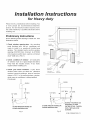
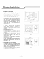
1, Check window opening size- the mounting
parts furnished with this air conditioner are
made to install in a wooden sill double-hung
window. The standard parts are for a window
opening of 32"(812 mm) minimum to 43"(1092
mm) maximum width. Open sash to a minimum
of 20" (508 mm), (FIG, 1)
2, Check condition of window- all wood parts
of window must be in good shape and able to
firmly hold the needed screws, If not, make
repairs before installing unit,
3, Check your storm windows- if your storm
window frame does not allow the clearance
required, correct by adding a piece of wood as
shown in FIG. 2, or by removing storm window
while room air conditioner is being installed,
(Continued)
1/2" MIN.
SASH
J
t
20" MIN.
STORMWINDOW FRAME OR
OTHER OBSTRUCTION
Fig. 1
FOAM
SASH SEAL
DOUBLE
SIDED SEAL
SIDE
ACCORDION
(RIGHT)
1/4,,x11/2,,
BOLT
MOUNTING
BRACKET
END CAP & ANGLE
LEVELING LEGS BRACKET
SIDE
ACCORDION
(LEFT)
SASH
f
' t
I
il 1/2" MIN. 20" MIN.
1/2" MIN. --_i I_-- I
T
% Zct ss
STORMWINDOW FRAME OR ENTIRE STOOL. FASTEN
OTHER OBSTRUCTION WITH TWO NAILS OR
SCREWS.
Fig. 2
P/N:819042102-01

4. CHECKFOR ANYTHING THATCOULD BLOCK
AIRFLOW-check area outside of window for
things such as shrubs, trees, or awnings.
Inside, besure furniture, drapes, orblinds will
not stop proper airflow.
5. Check the available electrical service- power
supply must be the same as that shown on the unit
serial nameplate, (See Owner's Guideforserial
plate location.) Power cord is 48"long. Besure
you have an outlet near. All models have a
3-prong service plug to provide proper service
and safe positive grounding, Do notchange plug
in any way. Do not use an adapter plug or an
extension cord. If your present wall outlet does
not match your plug, call a qualified electrician to
make the needed change,
Avoid fire hazard or
electric shock. Do not use an extension
cord or an adaptor plug. Do not remove
any prong from the power cord.
Grounding type wall
receptacle
_DDo not, under an-n-_y
circumstances, cut,
/ remove, or bypass J
_e grounding pro_
Power supply cord
with 3-prong grounding
plug and current
detection device
Tools Required
,/ Flat blade screwdriver
,/ Tape measure
,/ Adjustable wrench or pliers
,/ Pencil
./ Spirit level
,/ Socket wrenches
d Phillips screwdriver
J Powerdrilll/8" bit
d Scissors
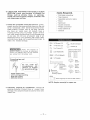
(]:ssssss>3/4"Screws (10) _ Shutter Clamp(2)
1/4"Screws (23) (_ Gasket(10)
[_ Top Channel(I)
Side Accordion RH(1)
O Lock Washers(4) Side Accordion LH(1)
(_ 1-1/2"xl/4 Bolts(4) _
@ 1/4" Nuts(4)
_o o o o o o o o o 7
ooooooooo_ool
[_ Mounting
Brackets(2)
Angle
racketsI2t
End Cap &
Leveling Legs(2)
Sash
Seal(l)
Double
Sided
Seal(l)
Widow
Foam (1)
Drain Plug(Only for 25K and 28K models)
NOTE: Surplus screw(s) for spare use.
6. Carefully unpack air conditioner- remove all
packing material. Protect floor or carpet from
damage, Two people should be used to move and
install unit,
--2--

Window installation
!
Because the compressor is located on the
controls side of the unit (right side), this side
will be heavier and more awkward to manipulate.
Inadequate support on control side of the unit
can result in personal injury and damage to your
unit and property. Therefore, it is recommended
to have someone assist you during the
installation of this unit.
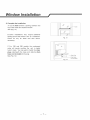
1. Select the Best Location
A. Your room air conditioner was designed to
fit easily into a single or double hung window.
However, since window designs vary, it may be
necessary to make some modifications for safe
and proper installation.
B. Make sure window and frame is structurally
sound and free from dry and rotted wood.
C. For maximum efficiency, install the air
conditioner on side of the house or building
which favors more shade than sunlight. If the
unit is in direct sunlight, it is advisable to provide
an awning over the unit.
D. Provide sufficient clearance around the
cabinet to allow for ample air circulation through
the unit. See (Fig.B). The rear of the unit should
be outdoors and not in a garage nor inside of a
building. Keep unit as far away as possible from
obstacles and obstructions and at least 30"
above the floor or ground. Curtains and other
objects within a room should be prevented from
blocking the air flow.
E. Be certain the proper electrical outlet is within
reach of the installation. All wiring should be in
accordance with local and national electrical
codes.
F. Your unit was designed to evaporate
condensation under normal conditions. However,
under extreme humidity conditions, excess
condensation may cause base pan to overflow to
the outside. The unit should be installed where
condensation run-off cannot drip on pedestrians
or neighboring properties.
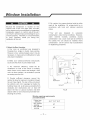
Awning
Fence,
wall, or
30" Min.
Side other
obstruction obstacle,i
Ground
Fig.B
Window opening requirements
(see table below)
Cabinet size
26.5" "18.5" *26.9"
(W*H*D)
Min. Window
30"
opening
Max. Window
44"
opening
i3i

Window installation
!
2. Preparation to Remove the Air Conditioner
From Slide-Out Chassis
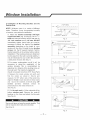
A. Place unit on floor, remove total of (4)
Philips screws securing the chassis to the
cabinet. There are (2) screws on each side.
The set of screws closest to the front of the
unit secure the front panel to the cabinet.
The set of screws closest to the rear of the unit
secure the cabinet to the chassis. See (Fig. 1).
NOTE: Screws must be reinstalled upon
completion of the window installation to
secure slide-out chassis.
B. Remove the front panel assembly from the
cabinet by gently pulling it.
C. Grasp the pull handle at the front of the
slide-out chassis and carefully slide the
air conditioner out of the cabinet. See (Fig. 2).
NOTE: Avoid touching coil in case of injury
or damage..
3. Assemble of the top channel to the cabinet
Stick the double sided seal to the top channel,
and then Install it to the cabinet as shown in
(Fig. 3) using (5) 1!4" screws.
de
Philips screws
Fig. 1
Coil
i
Chassis
Pull Handle
Fig. 2
Double
f sided seal
_ 1/4" Screws
_ Top Rail
4. Assemble of the accordions to the cabinet.
Slide the accordions into the top and bottom
channels as shown in (Fig. 4). The accordions
are identified (on each frame) as "left" & "right".
Attach the accordions to the cabinet using (4)
1/4" screws on each side.
Fig. 3
Accordion
/1/4" screws
Fig. 4
--4--

Window installation
!
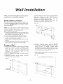
5. Installation of Mounting Brackets and the
Sealing Strip
NOTE: Windows come in a variety of different
styles. Therefore, it may be necessary to modify
or improve your particular installation.
A. Attach the bracket assembly to 90°angle
support brackets (Fig. 5) using (2) 1/4"X1 _"
bolts two bolts per bracket. Secure with the (2)
1/4" lock washers and (2) 1/4"nuts. DO NOT
immediately tighten these bolts as it may be
necessary to adjust the depth of the bracket
assembly, depending on the depth of your
window sill. See (Fig. 6).Install the two leveling
screws into the 90° support brackets. Test the
bracket assembly in the window before cabinet
installation. If the leveling screws are distanced
too far away from the wall to provide stability, it
may be necessary for you to shim this area with
a solid piece of wood. See (Fig. 7).
B. For proper condensation run-off it will be
necessary to adjust the angle/pitch of the
window brackets. This is accomplished by
adjusting the distance of the leveling screw on
the outer wall. The maximum angle/pitch
should not exceed more than 3/16". See (Fig.6).
C. Measure the inside window sill width and
find the center as shown in (Fig. 8), and
measure 12 3/5" either side of the center line.
Align the V-slot in each bracket on these marks
and mount the brackets to the sill using 3/4"
screws provided. Brackets should be
perpendicular to the inside window sill.
See (Fig. 8).
D. Cut the sash seal to fit the underside of the
bottom window sash. Remove the peel-off
backing on the foam and attach it to this sash.
See (Fig. 9).
! ,. e_ !
Use a solid piece of wood to provide stability. Thi_
will be required when sills are extra deep. /
See (Fig. 8). 1
(TOP VIEW)
Wslot_
_o o o o o o o o o ° I
o .... o....
/ /
Bracket Assembly
B__ 9O°Angle
Leve 2; soppor Brackets
Fig. 5
_4_ (2) 3/4" screws per bracket
o o O o o ..... _16"_laximum
Outer Wall Construction
Fig. 6
__ce Wood
(If required)
Fig. 7
Fig. 8
Window sill
Fig. 9
--5--

Window installation
/
6. Installation of the cabinet
A. Align one hole in the bottom of the cabinet
with one hole in the bracket assembly. Secure
the cabinet to the bracket using (3) 1/4" screws
provided. Repeat the same procedure on the
opposite side of the cabinet. See (Fig. 10).
B. Ensure the top rail is positioned in front of the
sash. The "U" shaped channel on the bottom of
the cabinet should be positioned in the track
provided on the bracket assembly. Pull the
window down until it rests just behind the top
rail. See (Fig. 11).
C. Check to make sure that the cabinet is
slanted slightly downward on the outside. If
necessary, re-adjust support bracket as shown
in (Fig. 6).
NOTE: Secure all hardware.
7. Secure Accordions
A. Carefully slide the air conditioner back into
the cabinet. (Please seek assistance for this
procedure).
B. Reinstall the slide-out-chassis security
screws (removed earlier) on both sides of the
cabinet. See (Fig. 12).
Secure the top of the leave same to the window
sash with (2) 3/4" screws.
C. Now, secure bottom frame of shutters using
one accordion clamp and one 3/4" screw on
each side (Fig. 12).
8. Reinstalling Front Panel Assembly
A. Position the front panel on the cabinet starting
at the top. The front panel lock tabs must be
inserted into the retaining slots in the cabinet.
Repeat this procedure on all sides.
B. Secure the front grille to the cabinet using the
Philips screws removed earlier(Fig. 1).
Fig. 10
Window Sash
Seal
Fig. 11
3/4" screws
Coil
Fig. 12
--6--

Window installation
/
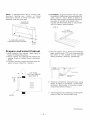
9. Complete the installation
A. Cut the foam to fit the opening between the
top of the inside and outside window.
See (Fig. 13).
B. Some installations may require additional
sealing around the window and air conditioner.
Check for any air leaks and seal where
necessary.
C. For 25K and 28K models, the condensed
water will maybe overflow the unit in highly
humid areas. You may wish to install the drain
plug underneath the base and attach a drain
hose (not included) to the plug.
See (Fig. 14).
Foam
Fig. 13
-_/F/
J/
_- Drain Plug
.......... _Drain Hose
(not included)
Fig. 14
--7--

Waft Installation
NOTE: Consult local building codes prior to
installation, ora qualified carpenter.
Select Wall Location
This airconditioner hasa slide-out chassis, so
it can be installed through an outside wall up to
12" thick. IMPORTANT: Side louvers must
never be blocked.
NOTE: All parts needed forWall Installation are
provided, exceptawood frame, shims, and 10
wood screws (#10-1" long minimum).
Select awall surface that:
1. does not support major structural loads such
as the frame construction at ends of windows,
and undertruss-bearing points, etc.
2. does not have plumbing orwiring inside.
3. is near existing electrical outlets, or where
another outletcan be installed.
4. faces, and is not blocked to the area to be
cooled.
5. allows unblocked airflow from rearsides and
end (outside) of installed air conditioner.
Prepare Wall
1. Preparewall inflame construction (including
brick and stucco veneer). Working from
inside the room, find wall stud nearest the
center of area where air conditionerwill be
installed (by sounding wall, or by
magnetically inding nails).
2. Cut or knock out a hole on each side of
center stud.
3. Measure between inside edges of every
other stud as shown in FIG. 1.
FIG. 1
Y
Carefully measureand cutan opening with the
following dimensions. See FIGS. 1 and 2.
WIDTH "X"=265/8" (68cm) plus twice the
thickness of framing material used.
HEIGHT"Y"= 185/8'' (47cm) plus twice the
thickness of framing material used.
FIG. 2
UP TO
8-1/2"
4, Build a wooden sleeve with the INSIDE
dimensions of 265/8" (68cm) inwidth and
185/8" (47cm) in height. Frame depth
should bethe sameas wallthickness. Fill in
the space from the opening tothe studswith
wood spacers, as shown in FIG,3,
5. Nail frame to spacers to studs with front
flush with drywall.
FIG. 3
NAIL SPACERS TOSTUDS
I
I} I
]
I
3-3/8" Min.
(8.6
I
I
I
I
I
I
I
I
I]
II //
i8i

NOTE: If wallthickness is8-1/2" ormore, add
aluminum flashing over bottom of frame
opening to assure no water can enter area
between innerand outerwall.
CAULK AS
REQUIRED
4. OPTIONAL: Support brackets may be used.
Installation brackets are recommended for
walls under 5" thick. Refer to Step4 of
Window Mounting for assembly of support
brackets. A wooden strip nailed to the
outside wall should be used in conjunction
with sill support angle brackets,
FIG. 2
1" LONG
WOOD SCREW
ALUMINUM FLASHING
OVER BOTTOM OF FRAME
OVER
8-1/2"
Prepare and Install Cabinet
1, Slide chassis from cabinet. Refer back to
Step 2of Window Mounting.
2, Place cabinet intoopeningwith bottom rail
resting firmly on bottom board ofwooden
frame,
3. Position cabinet toachieve proper slope for
water removal, (See FIG, 1 below,)
5, Secure bottom rail to wood frame with two
large wood screws 1"(2,5cm)long using the
two holes in the bottom of the channel
resting on frame, (See FIG, 2 following)
5/16"
TO
3/8"
LEVEL
3/4" PLUS
TRIM THICKNESS
SEE STEP 5
o o Oo o o oO o o J
_upport bracket
Wood
(If required)
6, Screwornailcabinet wooden frame using
shims if frame is oversized, to eliminate
distortion. Remember to maintain proper
slope as described in Step 3,
7, Installchassis into cabinet by following all
steps in Step 8of Window Mounting,
(Continued)
--9--

RECOMENDED: Caulking and installation of
trim on interior wall may be done. You can
buy wood from your local lumber or hardware
supply. On the outside, caulk openings
around top and sides of cabinet, and all
sides ofwood sleeve to theopening.
Masonry Construction
1. Cutor builda wall opening in the masonry
wall similar to the frame construction
(refer to Step 2 of Wall tnstallationfora
wall thickness greater than 8-1/2").
2. Secure cabinet in place using masonry
nails, or the right masonry anchor screws.
(Another way to do this is to build an
in-between frame of 2x4's as shown in the
Step 2 Prepare Wall illustrations-but make
itdoubleframedoneitherside, and install
between masonry wall opening and
cabinet. Frame must be securely anchored
tomasonrywall opening) This way gives
very good louver clearance on eitherside
of cabinet.
3. Install a lintel to support masonry wall
above cabinet. Existing holes in cabinet
can be used and/or additional holes can
be drilled to fasten cabinet at various
positions. Be sure that side louver
clearance is in accordance with Step 1
above.
4. Install exterior cabinet support brackets
as shown in Step 2 of Wall Installation.
Caulk or flash if need, to provide a
wether-tight seal around top and sides of
cabinet.
5. To complete installation, applywood trim
molding around room side projection of
cabinet.
--10--
-
 1
1
-
 2
2
-
 3
3
-
 4
4
-
 5
5
-
 6
6
-
 7
7
-
 8
8
-
 9
9
-
 10
10


Frigidaire FAS156P1A2 Installation guide
- Type
- Installation guide
- This manual is also suitable for
Ask a question and I''ll find the answer in the document
Finding information in a document is now easier with AI
Related papers
-
Frigidaire LRA08PZU113 Installation guide
-
Crosley LRA12HZT211 Installation guide
-
Gibson GAM185Q2A4 Installation guide
-
Crosley CAE10M15 Installation guide
-
-
-
Frigidaire FFRE153WA1 Installation guide
-
Frigidaire FFRA2822U2 Installation guide
-
-
Frigidaire FFRE2533U2 Installation guide
Other documents
-
 QMI CC-1 User guide
-
GE AEL24DV Installation guide
-
-
-
KoldFront WAC8001W Installation Instructions Manual
-
LG Electronics AXSVA1 Installation guide
-
Friedrich US10D30C Sleeve Installation
-
Carrier 73SC008A1C User manual
-
Gibson GAC102P1A1 Installation guide
-
Keystone KSTAW06CE User manual
