Page is loading ...

BEFORE YOU BEGIN
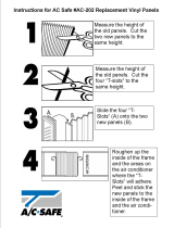
Read these instructions completely
and carefully.
t
IMPORTANT — Save these instructions
for local inspector’s use.
t
IMPORTANT — Observe all governing
codes and ordinances.
t
Note to Installer – Be sure to leave these
instructions with the Consumer.
t Note to Consumer – Keep these instructions for
future reference.
t Skill level – Installation of this appliance
requires basic mechanical skills.
t Completion time –
Approximately 1 hour
t We recommend that two people install
this product.
t Proper installation is the responsibility
of the installer.
t Product failure due to improper installation is not
covered under the Warranty.
t You MUST use all supplied parts and use proper
installation procedures as described in these
instructions when installing this air conditioner.
Installation
Air Conditioner
Instructions
Some models require a 115/120-volt AC,
60-Hz grounded outlet protected with a
15-amp time-delay fuse or circuit breaker.
The 3-prong grounding plug minimizes the
possibility of electric shock hazard. If the wall outlet
you plan to use is only a 2-prong outlet, it is your
responsibility to have it replaced with a properly
grounded 3-prong wall outlet.
Some models require 230/208-volt AC,
protected with a time-delay fuse or circuit
breaker. These models should be installed on
their own single branch circuit for best
performance and to prevent overloading
house or apartment wiring circuits, which
could cause a possible fire hazard from
overheating wires.
ELECTRICAL REQUIREMENTS
CAUTION:
Do not, under any circumstances, cut or remove
the third (ground) prong from the power cord.
Do not change the plug on the power cord
of this air conditioner.
Aluminum house wiring may present special
problems—consult a qualified electrician.
7
TOOLS YOU WILL NEED
Phillips head screwdriver
Ruler or tape measurePencil
Level
Scissors or knife
Flat-blade screwdriver
Power cord includes a current interrupter device. A
test and reset button is provided on the plug case. The
device should be tested on a periodic basis by first
pressing the TEST button and then the RESET button
while plugged into the outlet. If the TEST button does
not trip or if the RESET button will not stay engaged,
discontinue use of the air conditioner and contact a
qualified service technician.
Questions? Call 800.GE.CARES (800.432.2737) or Visit our Website at: GEAppliances.com
In Canada, call 1.800.561.3344 or visit www.GEAppliances.ca

8
Installation Instructions
Window
locking bracket
(1)
Top
mounting
rail
Sill angle
bracket (2)
Right
accordion
panel
Foam top window
gasket (1)
Left
accordion
panel
Window
sash seal
PARTS INCLUDED
(Appearance may vary)
Top rail gasket (1)
Type A
screws (10)
Type C
screws (5)
Type E bolt
with nut (4)
V-supports (2)
Type F bolt
with nut (2)
Side rail (2)

STORM WINDOW REQUIREMENTS
A storm window frame will not allow the air
conditioner to tilt toward the outside, and will keep it
from draining properly.
To adjust for this, attach a piece of wood to the sill.
WOOD PIECES
WIDTH: 2”
LENGTH: Long enough to fit inside the window
frame.
THICKNESS: The top of the wood should be 1/2”
higher than the top of the storm window frame or
the vinyl frame.
Attach securely with nails or screws provided by the
installer.
Installation Instructions
WINDOW REQUIREMENTS
tThese instructions are for a standard double-hung
window. You will need to modify them for other types
of windows.
tAll supporting parts must be secured
to firm wood, masonry or metal.
tThe electrical outlet must be within reach of the
power cord.
tFollow the dimensions in the table and illustration
for your model.
1
19 1/4”
(With accordion panels)
29” - 41”
2
1/2shigher
than storm
window
frame
Storm window
frame
Wood
Sill
1/2shigher
than vinyl frame
(on some windows)
Vinyl frame
9
PREPARE THE AIR CONDITIONER
Pull the top of the front panel out and down.
Remove the filter. Remove the front panel by
lifting up at an angle.
Remove the four front screws. Save them
for reinstalling the front housing.
Grasp the lower corners of the grille while
pressing in on the case sides with your
finger tips. Pull out to release and lift it up.
NOTE: Do not pull the bottom edge
toward you more than 3s or you may
damage the tabs of the grille.
When the front grille is removed the
control panel will still be attached by
a harness. Turn the grille around so
you can see the back side of the grille.
Remove the 2 screws to separate the
control panel housing from the grille.
NOTE: Be sure to save these screws. You will
need them later in the installation.
3
A
B
C
D

Installation Instructions
10
Installation Instructions
PREPARE THE AIR CONDITIONER
(continues)
Remove the shipping screws located on
the top of the case.
Remove the ground screws from each
side of the case. Keep them in a safe
location. NOTE: Be sure to save the ground
screws. You will need them later in the
installation.
Slide the air conditioner from the case
by gripping the base pan handle, lifting
up on the air conditioner, and pulling
forward. Have a second person brace the
case. Do not pull or lift on the styrofoam
discharge area.
Your unit may come with internal
packaging. This packaging must be
removed prior to installing the air
conditioner back into the cabinet.
3
E
F
FRONT
Do not
pull
or lift
in this
area—
damage
to the
unit may
result
PREPARE THE CASE
Attach the top rail gasket to the bottom
of the top mounting rail.
Install the top mounting rail with 4 type A
screws from the inside of the case. Press
firmly to drive the screws into the gasket
and through the top mounting rail.
Slide each side rail onto the edge of each
according panel. The figure shows the
orientation of each accordion panel and
side retainer assembly relative to the case
from a top view of the unit.
Slide the left and right accordion panels
into the top and bottom mounting rails.
A
Top mounting rail
B
4
G
H
C
D
Top left
Top right
Bottom mounting rail
Side Rail
Side Rail
Window Filler Panel
Window Filler Panel

Installation Instructions
11
PREPARE THE WINDOW AND INSTALL
THE CASE
Cut the window sash seal to the length of the
window sash. Peel off the backing and attach the
seal to the underside of the window sash.
Open the window and mark the center of
the window sill.
Carefully slide the case into the window
and center the case. Lower the window
behind the top mounting rail. Pull the
bottom of the case forward so that the
bottom mounting rail is tight against the
back of the window sill. Mount the case
to the window sill using 2 type C screws.
Drill pilot holes, if necessary.
5
PREPARE THE WINDOW AND INSTALL
THE CASE (continues)
Assemble the V-support and Sill Angle
bracket with Type F nut and bolt
Position the left
V-support under the left
side panel of the wall
case and against the
outside wall. Adjust the
Sill Angle Bracket to
rest on the sill. Attach
the V-support to the wall case using 2 Type
E bolts. Re-adjust the Sill Angle Bracket if
necessary.
Repeat with Right V-Support.
Extend the left and right accordion panels
to the vertical window sashes. Drill pilot
holes and attach the top corners with 2 type
C screws.
5
2 type C screws
Sill
B
A
C
D
V-support
F
Sill
V-support
G
E
Left
Sill angle
bracket
V-support Type
F bolt and nut
Right
Type E bolt
and nut
PREPARE THE CASE (continues)
Attach the side retainers to the case using 6
type A screws. Mount the screws from the
inside of the wall case.
4
E
Type C
screw
Type C
screw

Installation Instructions
12
5
PREPARE THE WINDOW AND INSTALL
THE CASE (continues)
Cut the foam top window gasket to the
window width.
Stuff the foam
between the
glass and the
window to
prevent air and
insects from getting into the room.
NOTE: If the gasket supplied does not fit
your window, obtain appropriate material
locally to provide a proper installation seal.
H
CAUTION:
To prevent broken
glass or damage to
windows, on vinyl or
other similarly
constructed windows,
attach the window
locking bracket to the window side jamb.
Attach the window locking
bracket with one Type C
screw.
I
J
Wood
Vinyl
INSTALL THE AIR CONDITIONER
IN THE CASE (continues)
Replace the 2 screws removed earlier, one
on each side of the case.
IMPORTANT: THE GROUND SCREWS MUST BE
REINSTALLED TO ENSURE PROPER GOUND.
Attach the front grille to the case by inserting
the tabs on the grille into the slots on the
front top of the case. Push the grille in.
Replace the screws.
Install the filter and the front grille.
Plug in the air conditioner.
6
B
C
INSTALL THE AIR CONDITIONER
IN THE CASE
Slide the air conditioner into the case by
the base pan. Do not push on the controls,
styrofoam air discharge housing or the finned
coils. Make sure the air conditioner is firmly
seated.
6
A
Do not press on
WKHVHDUHDV³
damage to the unit
may result
Base Pan
D
E
F

1313
Through-the-Wall Installation Instructions—Optional
The case may be installed through-the-wall
in both existing and new construction.
Read completely, then follow step-by-step.
NOTE: Obtain all materials locally for
mounting the air conditioner through-
the-wall.
IMPORTANT
Through-the-wall installation is not
appropriate if any of the side or top louvers
in the case will be obstructed by the wall.
All side and top louvers in the case must
project on the outdoor side of the wall.
The room side of the case must project
into the room far enough to maximize the
balance of the unit.
The case must be installed level from side-
to-side and with a slight tilt from front to
rear. Use a level; no more than a 1/2 bubble
will be the correct case slant to the outside.
Lintel angle is required to support bricks or
blocks above opening.
Flashing is required and should extend the
length of the opening to ensure no inside
cavity leakage occurs.
Remove the air conditioner from the case.
For specific instruction, refer to the Window
Installation Instructions.
Make certain that a wall receptacle is
available close to the hole location or make
arrangements to install a receptacle.
Place the case in the wall opening and
place wood support strips between the case
bottom and the flashing on both sides of the
bottom rail. They should be the same height
as the bottom rail and the same length as
the wall opening.
1
A
B
FINISH THE WALL OPENING
Caulk all four sides on the outdoor side of
the case to prevent moisture from getting
through to the interior wall. Use of flashing
(drip rail) will further prevent water from
dripping inside the wall and down the
outside of the building.
Place the air conditioner into the case.
For specific instruction, refer to the Window
Installation Instructions.
2
IMPORTANT (cont.)
Secure with 14 wood screws anchored at
least an inch into the wall support structure.
NOTE: Drill pilot holes, if necessary, for
proper installation. If the frame is oversized,
use shims to prevent case distortion.
1
D
A
B
Lintel angle
Plaster line
Trim molding (if
desired)
INSIDE
Bottom rail
Wood filler and
caulking (above and
below the flashing)
Air louvers (top
and sides must
project on the
outdoor side of
the wall)
OUTSIDE
Flashing
(Drip rail)
Case
bottom
Bottom
rail
Flashing
(Drip rail)
Wood support strips
Caulking
C
/