
COOKTOP INSTALLATION INSTRUCTIONS
INSTRUCCIONES DE INSTALACION DE
LASUPERFICIE DE COCCION
INSTRUCTIONS D'INSTALLATION DE
LATABLE DE CUISSON
Table of Contents / indice / Table des mati_res
COOKTOP SAFETY ......................................... 1
Tools and Parts ............................................. 2
Location Requirements ................................. 2
Electrical Requirements ................................ 3
Unpack Cooktop ........................................... 3
Install and Level Cooktop ............................. 3
Make Electrical Connection .......................... 4
Final Installation ............................................. 5
Complete Installation .................................... 5
SERVICE NUMBERS ................. BACK COVER
SEGURIDAD DE LA
SUPERFICIE DE COCCION ............................. 6
Piezas y herramientas ................................... 6
Requisites de ubicacion ................................. 6
Requisites el_etrioos ...................................... 7
Desempaque la superficie de cocci6n ......... 8
Instalacion y nivelaci6n de
la superficie de cocci6n ................................ 8
Come hacer la conexion el_ctrica ................ 9
Instalacion final ............................................ 10
Complete la instalaci6n ............................... 10
NUMEROS DE SERVICIO.CONTRAPORTADA
S#CURIT# DE LA TABLE DE CUISSON ...... 11
Outillage et pi_ces ....................................... 11
Emplacement d'installation ......................... 11
Specifications _lectriques ........................... 12
D_ballage de la table de cuisson ................ 13
Installation de la table de cuisson
et r_glage de I'aplomb ................................ 13
Raccordement _lectrique ............................ 14
Installation finale .......................................... 15
Achever I'installation ................................... 15
NUM#ROS
DE SERVICE ............. COUVERTURE ARRIERE
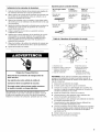
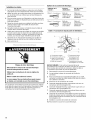
COOKTOP SAFETY
Your safety and the safety of others are very important.
We have provided many important safety messages in this manual and on your appliance. Always read and obey all
safety messages.
This is the safety alert symbol.
This symbol alerts you to potential hazards that can kill or hurt you and others.
All safety messages will follow the safety alert symbol and either the word "DANGER" or
"WARNING." These words mean:
You can be killed or seriously injured if you don't
immediately follow instructions.
You can be killed or seriously injured if you don't
follow instructions.
All safety messages will tell you what the potential hazard is, tell you how to reduce the chance of injury, and tell you
what can happen if the instructions are not followed.
IMPORTANT: Save installation instructions for local electrical inspector's use.
IMPORTANTE: Guarde las instrucciones de instalacidn para use del inspector electrico local.
IMPORTANT : Conserver les instructions d'installation a I'usage de I'inspecteur local des installations electriques.
IIIIIIIIIIIIIIIIII
9759088

Gather the required tools and parts before starting installation.
Tools needed
• Tape measure • Marker or pencil
• Flat-blade screwdriver • Pliers
Parts needed
• A UL or CSA conduit connector
• UL listed wire nuts
Parts supplied
• Cooktop
• 2 clamp brackets
• 21/2'' (6.4 cm) clamping screw
Check local codes. Check existing electrical supply. See
"Electrical Requirements."
All electrical connections should be made by a licensed, qualified
electrical installer.
Proper installation is your responsibility. Make sure you have
everything needed for correct installation. It is the responsibility
of the installer to comply with the installation clearances
specified in these instructions.
IMPORTANT: Observe all governing codes and ordinances.
When installing cooktop, use minimum dimensions given.
Cabinet storage space located above the surface units should be
avoided.
• The cooktop must be a specified cooktop that is approved to
be installed either alone or over an undercounter built-in
oven. Check the cooktop burner box for an approved
installation label. If you do not find this label, contact your
dealer to confirm that your cooktop is approved.
• Ovens approved for this type of installation will have an
approval label located on the top of the oven. If you do not
find this label, contact your dealer to confirm that your oven is
approved. Refer to oven manufacturer's Installation
Instructions for approval for built-in under use and proper
cutout dimensions.
• When installing cooktop over an undercounter built-in oven,
do not fasten cooktop to countertop with clamps. This will
make the cooktop easier to remove if future servicing
becomes necessary.
• The cooktop should be installed away from strong draft
areas, such as windows, doors and strong heating vents or
fans. The cooktop should be located for convenient use in the
kitchen.
• Use the countertop opening dimensions that are given with
these Installation Instructions. Given dimensions are
minimum clearances and provide 0" (0 cm) clearance.
• Grounded electrical supply is required. See "Electrical
Requirements" section.
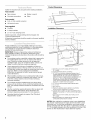
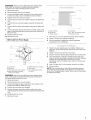
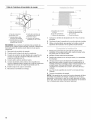
Product Dimensions
15" (38.1 cm)
30" (76.2 crn) or ......... \
36" (91.4 cm)
21-
(54,1
2-7/8" (7,3 cm)
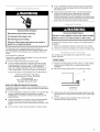
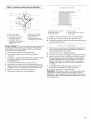
Installation Clearances
_--- A _l 13" (33 crn)
B I " _18" (45.7 cm) rain
c I 1
A. 30" (76.2 cm) on 30" models; 36" (91.4 cm) on
36" models
B. Combustible area above countertop
C. 30" (76.2 cm) minimum clearance between top of
cooktop platform and bottom of unprotected wood or
metal cabinet (24" [61 cm] minimum clearance if
bottom of wood or metal cabinet is protected by not
less than V4"[0.6 cm] flame retardant millboard
covered with not less than No. 28 MSG sheet steel,
0.015" [0.04 cm] stainless steel, or 0.024" [0.06 cm]
aluminum or 0.020" [0.05 cm] copper)
D. 13" (33 cm) recommended upper cabinet depth
E.2" (5.1 cm)
F. 20.5" (52 cm)
G. Minimum clearance upper cabinet to countertep
within minimum clearances to ceektep
H. Junction box or outlet," 12" (30.5 cm) minimum from
bottom of countertop; 10" (25.4 cm) from right side of
cabinet
I.29.5" (75 cm) on 30" models; 35.5" (90.2 cm) on
36" models
J. Minimum distance to nearest left and right side
combustible surface above cooktop
NOTES: After making the countertop cutout, some installations
may require notching down the base cabinet side walls to clear
the burner box. To avoid this modification, use a base cabinet
having sidewalls wider than the cutout. Ifcabinet has a drawer, a
3" (7.5 cm) depth clearance from the countertop to the top of the
drawer (or other obstruction) in base cabinet is required.

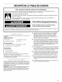
Electrical Shock Hazard
Disconnect power before servicing.
Use 8 gauge solid copper wire.
Electrically ground cooktop.
Failure to follow these instructions can result in
death, fire, or electrical shock.
If codes permit and a separate ground wire is used, it is
recommended that a qualified electrical installer determine that
the ground path and wire gauge are in accordance with local
codes.
Do not ground to a gas pipe.
Check with a qualified electrical installer if you are not sure the
cooktop is properly grounded.
Do not have a fuse in the neutral or ground circuit.
• To be sure that the electrical connection and wire size are
adequate and in conformance with the National Electrical
Code, ANSI/NFPA 70-latest edition or CSA Standards
C22.1-94, Canadian Electrical Code, Part 1 and C22.2 No.
O-M91-1atest edition, and all local codes and ordinances.
A copy of the above code standards can be obtained from:
National Fire Protection Association
Battewmarch Park, Quincy, MA 02269.
CSA International
8501 East Pleasant Valley Road
Cleveland, Ohio 44131-5575
Before You Make the Electrical Connection:
To properly install your cooktop, you must determine the type of
electrical connection you will be using and follow the instructions
provided for it here.
• A 4-wire, single phase 120/240-volt, 60Hz., AC-only electrical
supply is required (except for replacement in existing
installations) on a separate, 40-amp circuit, fused on both
sides of the line.
Locate the junction box to allow as much slack as possible
between the junction box and the cooktop so that the
cooktop can be moved if servicing becomes necessaw in the
future.
• Do not cut the conduit. Use the length of conduit provided.
A UL or CSA listed conduit connector must be provided at
each end of the power supply cable (at the cooktop and at
the junction box).
If the house has aluminum wiring, connect the aluminum
wiring to the copper wire by using special connectors
designed and UL listed for joining copper to aluminum.
Follow the electrical connector manufacturer's recommended
procedure. Aluminum/copper connection must conform with
local codes and industry accepted wiring practices.
To prevent floor damage, set the cooktop onto cardboard prior to
installation.
1. Remove the shipping materials and tape from the cooktop.
2. Remove the hardware package from inside the literature bag.
The cooktop may be installed with a panel trim kit or inside
custom cabinetry.
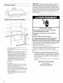
Install cooktop
1. Decide on the final location for the cooktop. Locate existing
wiring to prevent drilling into or severing wiring during
installation.
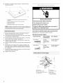
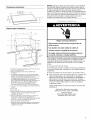
2. Place the cooktop upside down on a protective surface.
A. Burner box
B. Foam strip
3. Remove foam strip from literature package. Apply foam strip
around bottom of cooktop flush with edge. Turn cooktop right
side up.
4. Set the cooktop into the opening so that it is flush and
centered with the cabinetry facing.

5. Installthe2providedclampbracketsoneachendofthe
burnerboxbottom.
...................................................C
\
E
A. Attachment screw holes for optional front and back
location
B. Clamp bracket (end locations recommended)
C. Burner box bottom
D. Attachment screw
E.Attachment screw location (recommended)
NOTE: If cabinet construction does not provide clearance for
installing brackets at burner box ends, install the brackets on
the front and back of the burner box bottom.
Install clamp brackets
1. Remove the attachment screws for the bracket locations
selected from the bottom of the burner box.
2. Use bracket mounting holes that will allow the clamp screws
to contact the countertop bottom.
3. Attach brackets as shown, then rotate brackets so that they
do not extend beyond edge of burner box.
4. Tighten screws just enough to hold brackets in place when
cooktop is put into cutout.
5. Turn the cooktop right side up, and place the cooktop into the
cutout.
6. Check that the front edge of the cooktop is parallel to the
front edge of the countertop. If repositioning is needed, lift
the entire cooktop up from the cutout to prevent scratching
the countertop.
7. Loosen the screws. Rotate the brackets so that they extend
beyond edge of the burner box.
8. Tighten screws securely.
Electrical Shock Hazard
Disconnect power before servicing.
Use 8 gauge solid copper wire.
Electrically ground cooktop.
Failure to follow these instructions can result in
death, fire, or electrical shock.
This cooktop is manufactured with a frame connected, green
ground wire. Connect the cooktop cable to the junction box
through the UL or CSA listed conduit connector.
Electrical Connection Options
If your home has: And you will be Go to Section:
connecting to:
4-wire direct A fused 4-Wire Cable from
disconnect or Power Supply
circuit breaker
box
3-wire direct A fused 3-Wire Cable from
disconnect or Power Supply
circuit breaker
box
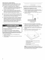
4-Wire Cable from Power Supply
B
C
A. Red wires
B. Bare or green wires
C. 4-Wire cable from cooktop
D. Junction box
G
H
E. White wires
F. UL listed wire nuts
G. Black wires
H. UL or CSA listed
conduit connector

REMEMBER: Use the 4-wire cable from power supply where
local codes do not permit connecting the frame-ground
conductor to the neutral (white) junction box wire.
1. Disconnect power.
2. Remove junction box cover if present.
3. Connect the flexible cable conduit from the cooktop to the
junction box using a UL or CSA listed conduit connector.
4. Tighten screws on conduit connector.
5. Connect the two black wires together using the UL listed wire
nuts.
6. Connect the two red wires together using the UL listed wire
nuts.
7. Connect the two white wires together using the UL listed wire
nuts.
8. Connect the green ground wire from the cooktop cable to the
green or bare grounded wire (in the junction box) using the UL
listed wire nuts.
9. Install junction box cover.
10. Reconnect power.
3-Wire Cable from Power Supply
A. Junction box
B. Red wires
C. White wire (from power supply)
D. White and green grounding
wires (from cooktop)
E.4-Wire cable from cooktop
F. Black wires
G. UL or CSA listed conduit
connector
REMEMBER: Use the 3-wire cable from power supply where
local codes permit connecting the frame-ground conductor to
the neutral (white) junction box wire:
1. Disconnect power.
2. Remove junction box cover if present.
3. Connect the flexible, cable conduit from the cooktop to the
junction box using UL listed wire nuts.
4. Connect the two black wires together.
5. Connect the green and white cooktop cable wires to the
white (neutral) wire in the junction box using the UL listed wire
nuts.
6. Install junction box cover.
7. Reconnect power.
A. Glass cooktop
B. Burner box
C. Clamp bracket
D. Countertop
E.2 W' (6.4 cm) clamping screw
F. Attachment screw
1. Place the 2.5" (6.4 cm) clamping screws into the brackets.
2. Check to be sure the cooktop is still level.
3. Use a screwdriver to tighten the screws against the
countertop. Do not overtighten.
1. Check to be sure all parts are now installed. If there is an
extra part, go back through the steps to see which step was
skipped.
2. Check to be sure you have all of your tools.
3. Dispose of/recycle all packaging materials and unused parts.
4. Use a mild solution of liquid household cleaner and warm
water to remove waxy residue caused by protective shipping
material. Dry thoroughly with a soft cloth. For more
information, see the "Cooktop Care" section of the Use and
Care Guide.
5. Read "Cooktop Use" in the cooktop Use and Care Guide.
6. Connect power.
NOTE: If the cooktop will not work after turning the power on,
check that the circuit breaker is not tripped or the house fuse
blown. See "Troubleshooting" section in the Use and Care Guide
for further information.
Page is loading ...
Page is loading ...
Page is loading ...
Page is loading ...
Page is loading ...
Page is loading ...
Page is loading ...
Page is loading ...
Page is loading ...
Page is loading ...

iiiiiiiiiiiiiiiiiiiiiii;....
Your Home
For repair-in your home-of all major brand appliances,
lawn and garden equipment, or heating and cooling systems,
no matter who made it, no matter who sold it!
For,the replacement parts, accessories and
owner s manuals that you need to do-it-yourself.
For Sears professional installation of home appliances
and items like garage door openers and water heaters.
1-800-4-MY-HOME ® (1-800-469-4663)
Call anytime, day or night (U.S.A. and Canada)
www.sears.com www.sears.ca
Our Home
For repair of carry-in items like vacuums, lawn equipment,
and electronics, call or go on-line for the location of your nearest
Sears Parts& RePair Center.
1 800 488 1222
Call anytime, day or night (U.S.A. only)
www.sears.com
a domicilio, y para ordenar piezas:
1-888-SU-HOGAR sM
1-800-LE-FOYER Mc
(1-800-533-6937)
www.sears.ca
9759088
© Sears, Roebuck and Co.
, TM SM ,
® Registered Trademark / Trademark / Serwce Mark of Sears, Roebuck and Co.
, TM
® Mama Registrada / Marca de Comerclo / SMMarca de Servicio de Sears, Roebuck and Co.
MC MD
Marque de commerce / Marque d_posee de Sears, Roebuck and Co.
6/04
Printed in U.S.A.
Impreso en EE. UU.
Imprim6 aux E.-U.
-
 1
1
-
 2
2
-
 3
3
-
 4
4
-
 5
5
-
 6
6
-
 7
7
-
 8
8
-
 9
9
-
 10
10
-
 11
11
-
 12
12
-
 13
13
-
 14
14
-
 15
15
-
 16
16


Ask a question and I''ll find the answer in the document
Finding information in a document is now easier with AI
in other languages
- français: Kenmore 66544054301 Guide d'installation
- español: Kenmore 66544054301 Guía de instalación
Related papers
-
Kenmore Elite 66544094501 Installation guide
-
Kenmore Elite 66578009801 Installation guide
-
Crosley CE11000VAV0 Installation guide
-
Kenmore 362.7223 Series Owner's manual
-
Kenmore 91147759200 Installation guide
-
Sears 66561632100 Owner's manual
-
Kenmore Elite 79046709603 Installation guide
-
-
-
Other documents
-
IKEA ICR444DB00 Installation guide
-
KitchenAid KECC056RBL Installation guide
-
-
Maytag JEC4536BS00 Installation guide
-
KitchenAid KICU568SBL1 Installation guide
-
IKEA IBS324PVS0 Installation guide
-
-
KitchenAid KICU540BSS0 Installation guide
-
Maytag MEC7430WW01 Installation guide
-
Whirlpool KECC562GWH05 Installation guide