KitchenAid KECC056RBL Installation guide

Category
Cookers
Type
Installation guide

KitchenAid KECC056RBL: Enhance your culinary skills with this state-of-the-art electric cooktop. Featuring a sleek and stylish design, this cooktop seamlessly integrates into your modern kitchen. Equipped with powerful heating elements, it delivers precise temperature control for consistent cooking results every time. The intuitive touch controls provide a user-friendly experience, allowing you to effortlessly adjust heat settings and monitor cooking progress.

KitchenAid KECC056RBL: Enhance your culinary skills with this state-of-the-art electric cooktop. Featuring a sleek and stylish design, this cooktop seamlessly integrates into your modern kitchen. Equipped with powerful heating elements, it delivers precise temperature control for consistent cooking results every time. The intuitive touch controls provide a user-friendly experience, allowing you to effortlessly adjust heat settings and monitor cooking progress.

ELECTRIC COOKTOP INSTALLATION INSTRUCTIONS
INSTRUCTIONS D’INSTALLATION DE
LATABLE DE CUISSON
COOKTOP SAFETY
8286066
Table of Contents Table des Matières
COOKTOP SAFETY.................................1
INSTALLATION INSTRUCTIONS ...........2
Tools and Parts .....................................2
Location Requirements .........................2
Electrical Requirements.........................3
Prepare Cooktop for Installation ...........4
Install Cooktop ......................................5
Make Electrical Connection ..................6
Attach Cooktop to Countertop..............8
Complete Installation.............................8
SÉCURITÉ DE LA TABLE DE CUISSON9
INSTRUCTIONS D’INSTALLATION .......9
Outillage et pièces................................. 9
Exigences d’emplacement.................... 9
Spécifications électriques ...................11
Préparation de la table de cuisson
pour l'installation ................................. 12
Installation de la table de cuisson....... 13
Raccordement électrique.................... 14
Fixation de la table de cuisson
au plan de travail ................................. 16
Achever l'installation ...........................16
You can be killed or seriously injured if you don't immediately
You
can be killed or seriously injured if you don't
follow
All safety messages will tell you what the potential hazard is, tell you how to reduce the chance of injury, and tell you what can
happen if the instructions are not followed.
Your safety and the safety of others are very important.
We have provided many important safety messages in this manual and on your appliance. Always read and obey all safety
messages.
This is the safety alert symbol.
This symbol alerts you to potential hazards that can kill or hurt you and others.
All safety messages will follow the safety alert symbol and either the word “DANGER” or “WARNING.”
These words mean:
follow instructions.
instructions.
DANGER
WARNING
IMPORTANT:
Installer: Leave installation instructions with the homeowner.
Homeowner: Keep installation instructions for future reference.
Save installation instructions for local electrical inspector's use.
IMPORTANT :
Installateur : Remettre les instructions d'installation au propriétaire.
Propriétaire : Conserver les instructions d'installation pour référence ultérieure.
Conserver les instructions d'installation pour consultation par l'inspecteur local des installations électriques.
2
INSTALLATION INSTRUCTIONS
Tools and Parts
Gather the required tools and parts before starting installation.
Tools needed
Parts supplied
Clamp brackets (2)
2¹⁄₂" (6.4 cm) clamping screws (2)
Parts needed
A UL listed or CSA approved conduit connector
UL listed wire nuts
Check local codes. Check existing electrical supply. See
Electrical Requirements.
All electrical connections should be made by a licensed, qualified
electrical installer.
Location Requirements
Proper installation is your responsibility. Make sure you have
everything needed for correct installation. It is the responsibility of
the installer to comply with the installation clearances specified in
these instructions.
IMPORTANT: Observe all governing codes and ordinances. When
installing cooktop, use minimum dimensions given.
To eliminate the risk of burns or fire by reaching over the
heated surface units, cabinet storage space located above the
surface units should be avoided. If cabinet storage is to be
provided, the risk can be reduced by installing a range hood
that projects horizontally a minimum of 5" (12.7 cm) beyond
the bottom of the cabinets.
The cooktop must be a specified cooktop that is approved to
be installed either alone or over an undercounter built-in oven.
Check the cooktop burner box for an approved installation
label. If you do not find this label, contact your dealer to
confirm that your cooktop is approved.
Ovens approved for this type of installation will have an
approval label located on the top of the oven. If you do not
find this label, contact your dealer to confirm that your oven is
approved. Refer to oven manufacturers Installation
Instructions for approval for built-in undercounter use and
proper cutout dimensions.
When installing cooktop over an undercounter built-in oven,
do not fasten cooktop to countertop with clamps. This will
make the cooktop easier to remove if future servicing
becomes necessary.
The cooktop should be installed away from strong draft areas,
such as windows, doors, fans or strong heating vents. The
cooktop should be located for convenient use in the kitchen.
Use the countertop opening dimensions that are given with
these Installation Instructions. Given dimensions are minimum
clearances and provide 0" (0 cm) clearance.
Grounded electrical supply is required. See Electrical
Requirements section.
Product Dimensions
Straight-edge cooktop
Curved-edge cooktop
Tape meas ure
Flat-blade screwdriver
Marker or pencil
Pliers
A. 21⁵⁄₁₆" (54.1 cm)
B. 16⁹⁄₁₆" (42.1 cm)
30⁵⁄₁₆" (77.1 cm)
36⁵⁄₁₆" (92.3 cm)
C. 2⁷⁄₈" (7.3 cm)
A. 22¹⁄₈" (56.1 cm)
B. 16⁹⁄₁₆" (42.1 cm)
30⁵⁄₁₆" (77.1 cm)
36⁵⁄₁₆" (92.3 cm)
C.2⁷⁄₈" (7.3 cm)
C
A
B
A
B
C
3
Installation Clearances
NOTES: After making the countertop cutout, some installations
may require notching down the base cabinet side walls to clear
the burner box. To avoid this modification, use a base cabinet with
sidewalls wider than the cutout.
If cabinet has a drawer, a 3" (7.6 cm) depth clearance from the
countertop to the top of the drawer (or other obstruction) in base
cabinet is required.
When installing a hood above this cooktop, follow the installation
instructions included with the hood itself.
For model 15" (38.1 cm) model only:
Electrical Requirements
For 15" (38.1 cm) model only:
For all models except 15" (38.1 cm) model:
If codes permit and a separate ground wire is used, it is
recommended that a qualified electrical installer determine that
the ground path and wire gauge are in accordance with local
codes.
A. 15" (38.1 cm) on 15" (38.1 cm) models; 30" (76.2 cm) on
30" (76.2 cm) models; 36" (91.4 cm) on 36" (91.4 cm) models
B. Combustible area above countertop (shown by dashed box above)
C. 30" (76.2 cm) minimum clearance between top of cooktop platform
and bottom of unprotected wood or metal cabinet (24" [61 cm]
minimum clearance if bottom of wood or metal cabinet is protected
by not less than ¹⁄₄" [0.6 cm] flame retardant millboard covered with
not less than No. 28 MSG sheet steel, 0.015" [0.04 cm] stainless
steel, or 0.024" [0.06 cm] aluminum or 0.020" [0.05 cm] copper)
D. 13" (33 cm) recommended upper cabinet depth
E. 2" (5.1 cm)
F. 20½" (52 cm)
G. 18" (45.7 cm) minimum clearance from upper cabinet to countertop
within minimum horizontal clearances to cooktop
H. Junction box or outlet; 12" (30.5 cm) minimum from bottom of
countertop; 10" (25.4 cm) from right side of cabinet
I. 14½" (36.8 cm) on 15" (38.1 cm) models; 29½" (74.9 cm) on
30" (76.2 cm) models; 35½" (90.2 cm) on 36" (91.4 cm) models
J. 1" (2.5 cm) minimum distance to nearest left and right side
combustible surface above cooktop
K. 1½" (3.8 cm) max. counter thickness on 15" (38.1 cm) models. See
following illustration.
L. 1" (2.5 cm) minimum clearance between back wall and countertop
B
D
A
C
E
F
H
I
J
G
H
K
L
A. ¹¹⁄₁₆" (1.7 cm) min.
B. 1½" (3.8 cm) max.
back edge
of cutout
rear of cabinet or
rear wall under
countertop
B
A
WARNING
Electrical Shock Hazard
Disconnect power before servicing.
Use 12 gauge copper wire.
Electrically ground cooktop.
Failure to follow these instructions can result in death,
fire, or electrical shock.
WARNING
Electrical Shock Hazard
Disconnect power before servicing.
Use 8 gauge copper wire.
Electrically ground cooktop.
Failure to follow these instructions can result in death,
fire, or electrical shock.
4
Do not ground to a gas pipe.
Check with a qualified electrical installer if you are not sure the
cooktop is properly grounded.
Do not have a fuse in the neutral or ground circuit.
Make sure that the electrical connection and wire size are
adequate and in conformance with the National Electrical Code,
ANSI/NFPA 70-latest edition or CSA Standards C22.1-94,
Canadian Electrical Code, Part 1 and C22.2 No. O-M91-latest
edition, and all local codes and ordinances.
A copy of the above code standards can be obtained from:
National Fire Protection Association
One Batterymarch Park
Quincy, MA 02269
CSA International
8501 East Pleasant Valley Road
Cleveland, OH 44131-5575
Before You Make the Electrical Connection:
To properly install your cooktop, you must determine the type of
electrical connection you will be using and follow the instructions
provided for it here.
A 4-wire or 3-wire, single phase, 240 volt, 60 Hz., AC only
electrical supply is required on a separate, 40-amp circuit,
fused on both sides of the line.
NOTE: The 15" (38.1 cm) model series requires a 20-amp
circuit.
The cooktop should be connected directly to the junction box
through flexible, armored or nonmetallic sheathed, copper
cable. The flexible, armored cable extending from the fuse box
or circuit breaker box should be connected directly to the
junction box.
Locate the junction box to allow as much slack as possible
between the junction box and the cooktop so that the cooktop
can be moved if servicing becomes necessary in the future.
Do not cut the conduit. Use the length of conduit provided.
A UL listed or CSA approved conduit connector must be
provided at each end of the power supply cable (at the
cooktop and at the junction box). A listed conduit connector is
already provided at the cooktop.
If the house has aluminum wiring, connect the aluminum
wiring to the copper wire by using special connectors
designed and UL listed for joining copper to aluminum. Follow
the electrical connector manufacturers recommended
procedure. Aluminum/copper connection must conform with
local codes and industry accepted wiring practices.
Prepare Cooktop for Installation
1. Decide on the final location for the cooktop. Locate existing
wiring to prevent drilling into or severing wiring during
installation.
2. Place the cooktop upside down on a protective surface.
3. Remove foam strip from literature packing. Remove backing
from foam strip. Apply foam strip adhesive-side down around
bottom of cooktop, flush with edge.
NOTE: The foam strip protects the underside of the cooktop
glass from debris and helps the cooktop sit flat on uneven
counters.
A. Burner box
B. Foam strip
WARNING
Excessive Weight Hazard
Use two or more people to move and install cooktop.
Failure to do so can result in back or other injury.
A
B
5
Install Cooktop
Style 1: Cooktop over undercounter built-in oven
IMPORTANT: Clamp brackets should not be used.
1. Turn cooktop right side up.
2. Place cooktop in cutout.
NOTE: Make sure that the front edge of the cooktop is parallel
to the front edge of the countertop. If repositioning is needed,
lift entire cooktop up from cutout to prevent scratching the
countertop.
Style 2: Cooktop over cabinets
1. Determine whether your cabinet construction provides
clearance for installing clamp brackets at burner box ends.
This is the recommended location. Clamp brackets can be
installed on the front and back of burner box bottom, if
necessary.
2. The clamp brackets can be installed before or after the
cooktop is placed into the cutout. Complete the following
steps for the option you choose.
Installing Brackets Before Placing Cooktop in Cutout
1. Remove the attachment screws for the selected bracket
locations from the bottom of the burner box.
2. Select bracket mounting holes that will allow the bracket to
extend far enough out from the cooktop for the installation of
2½" (6.4 cm) clamping screws. See Attach Cooktop to
Countertop for illustration of clamping screw installation.
3. Attach brackets to burner box bottom with bracket
attachment screws using the bracket mounting holes selected
in Step 2.
4. Rotate brackets so they do not extend beyond edge of burner
box.
5. Tighten screws just enough to hold brackets in place when
cooktop is put in cutout.
6. Turn the cooktop right side up and place in cutout.
NOTE: Make sure that the front edge of the cooktop is parallel
to the front edge of the countertop. If repositioning is needed,
lift entire cooktop up from cutout to prevent scratching the
countertop.
7. Loosen the screws and rotate the brackets so that they are
perpendicular to the edge of the burner box and extend
beyond its edge. Securely tighten screws.
Installing Brackets After Placing Cooktop in Cutout
1. Place cooktop in cutout.
NOTE: Make sure that the front edge of the cooktop is parallel
to the front edge of the countertop. If repositioning is needed,
lift entire cooktop up from cutout to prevent scratching the
countertop.
2. Remove the attachment screws for the selected bracket
locations from the bottom of the burner box.
3. Select bracket mounting holes that will allow the bracket to
extend far enough out from the cooktop for the installation of
2½" (6.4 cm) clamping screws.
4. Attach brackets to burner box bottom with bracket
attachment screws using the bracket mounting holes selected
in Step 3. Securely tighten screws.
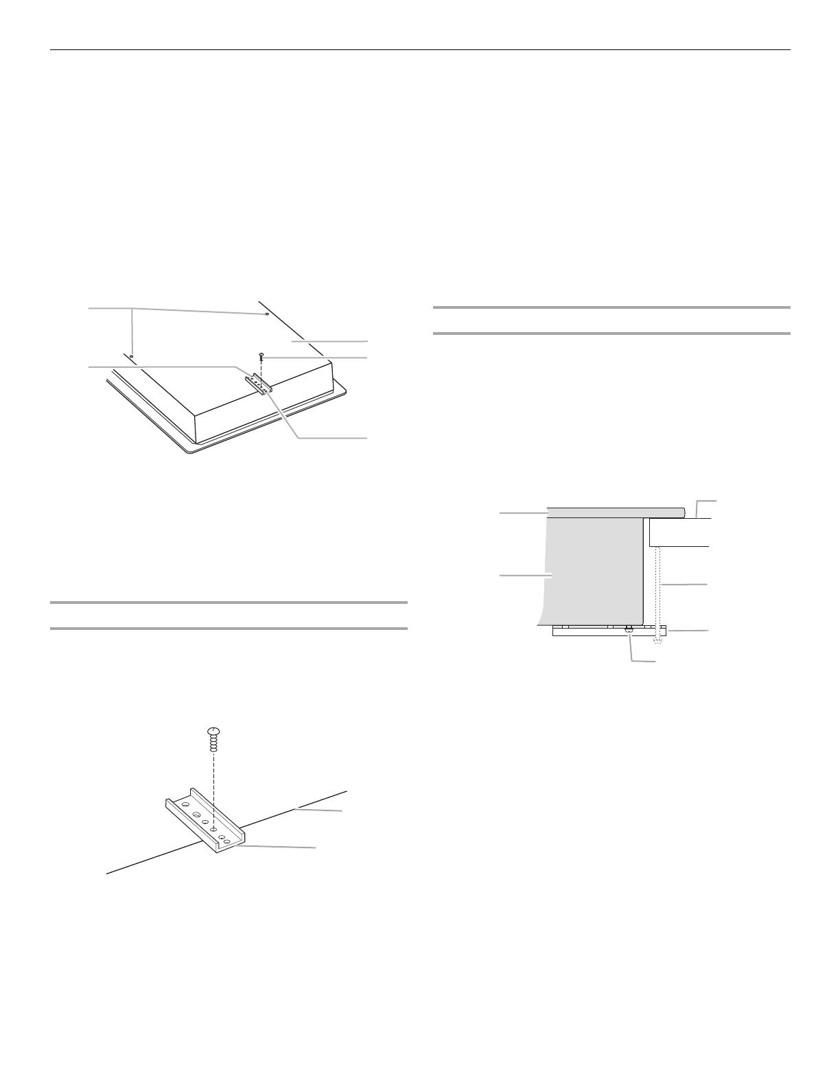
A. Attachment screw holes for optional front and back
location
B. Clamp bracket (end locations recommended)
C. Burner box bottom
D. Attachment screw
E. Attachment screw location (recommended)
A. Edge of burner box bottom
B. Clamp bracket
A
B
C
D
E
A
B
A. Glass cooktop
B. Burner box
C. Attachment screw
D. Clamp bracket (extends far enough beyond
burner box to allow installation of clamping
screws)
E. 2½" (6.4 cm) clamping screw (to be installed in
Attach Cooktop to Countertop)
F. Countertop
A
B
C
D
E
F
6
Make Electrical Connection
For 15" (38.1 cm) model only:
For all models except 15" (38.1 cm) model:
This cooktop is manufactured with a frame connected, green or
bare ground wire. Connect the cooktop cable to the junction box
through the UL listed or CSA approved conduit connector.
Electrical Connection Options
4-Wire Cable from Power Supply to 4-Wire Cable from
Cooktop
IMPORTANT: Use the 4-wire cable from power supply where local
codes do not permit connecting the frame-ground conductor to
the neutral (white) junction box wire.
1. Disconnect power.
2. Remove junction box cover, if present.
WARNING
Electrical Shock Hazard
Disconnect power before servicing.
Use 12 gauge copper wire.
Electrically ground cooktop.
Failure to follow these instructions can result in death,
fire, or electrical shock.
WARNING
Electrical Shock Hazard
Disconnect power before servicing.
Use 8 gauge copper wire.
Electrically ground cooktop.
Failure to follow these instructions can result in death,
fire, or electrical shock.
For cooktops with a 4-wire cable:
If your home has: And you will be
connecting to:
Go to Section:
4-wire direct A fused
disconnect or
circuit breaker
box
4-Wire Cable from
Power Supply to
4-Wire Cable from
Cooktop
3-wire direct A fused
disconnect or
circuit breaker
box
3-Wire Cable from
Power Supply to
4-Wire Cable from
Cooktop
For cooktops with a 3-wire cable:
If your home has: And you will be
connecting to:
Go to Section:
4-wire direct A fused
disconnect or
circuit breaker
box
4-Wire Cable from
Power Supply to
3-Wire Cable from
Cooktop
3-wire direct A fused
disconnect or
circuit breaker
box
3-Wire Cable from
Power Supply to
3-Wire Cable from
Cooktop
A. Red wires
B. Bare or green wires
C. 4-Wire cable from cooktop
D. Junction box
E. White wires
F. UL listed wire nut
G. Black wires
H. UL listed or CSA approved
conduit connector
5"
(12.7 cm)
3¹₂"
(8.9 cm)
5"
(12.7 cm)
3¹₂"
(8.9 cm)
A
B
C
D
E
F
G
H
7
3. Connect the flexible cable conduit from the cooktop to the
junction box using a UL listed or CSA approved conduit
connector.
4. Tighten screws on conduit connector if present.
5. Connect the two black wires together using the UL listed wire
nuts.
6. Connect the two red wires together using the UL listed wire
nuts.
7. Connect the two white wires together using the UL listed wire
nuts.
8. Connect the green or bare ground wire from the cooktop
cable to the green or bare ground wire (in the junction box)
using the UL listed wire nuts.
9. Install junction box cover.
10. Reconnect power.
3-Wire Cable from Power Supply to 4-Wire Cable from
Cooktop
IMPORTANT: Use the 3-wire cable from power supply where local
codes permit connecting the frame-ground conductor to the
neutral (white) junction box wire:
1. Disconnect power.
2. Remove junction box cover if present.
3. Connect the flexible, cable conduit from the cooktop to the
junction box using UL listed or CSA approved conduit
connector.
4. Tighten screws on conduit connector, if present.
5. Connect the two black wires together using the UL listed wire
nuts.
6. Connect the two red wires together using the UL listed wire
nuts.
7. Connect the green or bare and white cooktop cable wires to
the white (neutral) wire in the junction box using the UL listed
wire nuts.
8. Install junction box cover.
9. Reconnect power.
4-Wire Cable from Power Supply to 3-Wire Cable from
Cooktop
IMPORTANT: Use the 4-wire cable from power supply where local
codes do not permit connecting the frame-ground conductor to
the neutral (white) junction box wire:
1. Disconnect power
2. Remove junction box cover if present.
3. Connect the flexible cable conduit from the cooktop to the
junction box using a UL listed or CSA approved conduit
connector.
4. Tighten screws on conduit connector, if present.
5. Connect the two black wires together using the UL listed wire
nuts.
6. Connect the two red wires together using the UL listed wire
nuts.
7. Connect the green or bare ground wire from the cooktop
cable to the green or bare ground wire (in the junction box)
using the UL listed wire nuts.
8. Put a UL listed wire nut on the end of the white wire.
NOTE: Do not connect the bare ground wire to the neutral
(white) wire in the junction box.
9. Install junction box cover.
10. Reconnect power.
A. Red wires
B. White and green or bare
ground wires (from cooktop)
C. 4-Wire cable from cooktop
D. Junction box
E. White wire (from power supply)
F. UL listed wire nut
G. Black wires
H. UL listed or CSA approved
conduit connector
B
C
D
E
F
H
A
G
A. Red wires
B. Green or bare ground wire
(from cooktop)
C. 3-Wire cable from cooktop
D. Junction box
E. White wire (from power supply)
F. UL listed wire nut
G. Black wires
H. UL listed or CSA approved
conduit connector
A
B
C
D
E
F
H
G
8
3-Wire Cable from Power Supply to 3-Wire Cable from
Cooktop
IMPORTANT: Use the 3-wire cable from power supply where local
codes permit connecting the frame-ground conductor to the
neutral (white) junction box wire:
1. Disconnect power
2. Remove junction box cover, if present.
3. Connect the flexible cable conduit from the cooktop to the
junction box using a UL listed or CSA approved conduit
connector.
4. Tighten screws on conduit connector if present.
5. Connect the two black wires together using the UL listed wire
nuts.
6. Connect the two red wires together using the UL listed wire
nuts.
7. Connect the green or bare cooktop cable wires to the white
(neutral) wire in the junction box using the UL listed wire nuts.
8. Install junction box cover.
9. Reconnect power.
Attach Cooktop to Countertop
NOTE: This section applies only if you are using clamp brackets.
1. Place the 2½" (6.4 cm) clamping screws into the brackets.
2. Check to be sure the cooktop is still level.
3. Use a flat-blade screwdriver to tighten the screws against the
countertop. Do not overtighten.
Complete Installation
1. Check that all parts are now installed. If there is an extra part,
go back through the steps to see which step was skipped.
2. Dispose of/recycle all packaging materials.
3. Use a mild solution of liquid household cleaner and warm
water to remove waxy residue caused by protective shipping
material. Dry thoroughly with a soft cloth. For more
information, see the Cooktop Care section of the
Use and Care Guide.
4. Read Cooktop Use in the cooktop Use and Care Guide.
NOTE: If the cooktop does not work after turning on the power,
check that a circuit breaker has not tripped or a house fuse has
not blown. See Troubleshooting section in the Use and Care
Guide for further information.
If you need Assistance or Service:
Please reference the Assistance or Service section of the Use
and Care Guide or contact the dealer from whom you purchased
your cooktop.
A. Red wires
B. Bare or green wire from
cooktop
C. 3-wire cable (from cooktop)
D. Junction box
E. White wire (from power supply)
F. UL listed wire nut
G. Black wire
H. UL listed or CSA approved
conduit connector
G
A
B
C
D
E
F
H
A. Glass cooktop
B. Burner box
C. Clamp bracket
D. Countertop
E. 2½
" (6.4 cm) clamping screw
F. Attachment screw
A
B
C
D
E
F
  • Page 1 1
  • Page 2 2
  • Page 3 3
  • Page 4 4
  • Page 5 5
  • Page 6 6
  • Page 7 7
  • Page 8 8
  • Page 9 9
  • Page 10 10
  • Page 11 11
  • Page 12 12
  • Page 13 13
  • Page 14 14
  • Page 15 15
  • Page 16 16

KitchenAid KECC056RBL Installation guide

Category
Cookers
Type
Installation guide

KitchenAid KECC056RBL: Enhance your culinary skills with this state-of-the-art electric cooktop. Featuring a sleek and stylish design, this cooktop seamlessly integrates into your modern kitchen. Equipped with powerful heating elements, it delivers precise temperature control for consistent cooking results every time. The intuitive touch controls provide a user-friendly experience, allowing you to effortlessly adjust heat settings and monitor cooking progress.

Ask a question and I''ll find the answer in the document

Finding information in a document is now easier with AI

in other languages