Page is loading ...

Owner’s Manual — Phoenix Solution LGR
Performance Amplifier
Installation, Operation & Service Instructions
1
www.UsePhoenix.com • [email protected]Toll-Free 1-800-533-7533
Read and Save These Instructions
The new Phoenix Solution LGR Performance Amplifier widens
the effective operating range of LGR dehumidifiers, increases
grain depression, and improves water removal rates up to 100
percent.
The Solution is a specially designed intercooler that pre-cools
the incoming air stream to the LGR dehumidifier. This pre-
cooling is the same process that provides LGR dehumidifiers
with their leap in performance over conventional dehumidifiers.
The Solution is designed to take advantage of outside,
unaffected or air conditioned air to provide significant water
removal in drying conditions up to 140°F. Therma-Stor testing
has revealed an increase in water removal rates and faster
drying times using the Solution by utilizing cold outside air.
The Solution improves the grain depression of the dehumidified
air. This increases the vapor pressure differential (the key to
evaporation) up to 33% and accelerates the drying process.
This improves drying times in all classes of water damage but is
particularly beneficial in specialty drying applications, such as
hardwood floors.
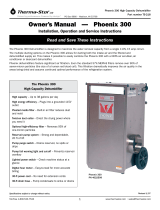
The Phoenix Solution
LGR Performance Amplifier
• WidensthetemperaturerangeforLGRperformance
up to 140°F.
• Increaseswaterremovalratesupto100%.
• Increasesgraindepressionupto33%forfaster
drying of more materials.
• RemovesBTUsfromtheaffectedareas.
• Achievesoptimaldryingconditionsinstructures
with insufficient or without air conditioning.
• Drivesthegrains/lb.inthedryingareafromthemid
30’s to the low 20’s.
• Enhancestheperformanceofheatbasedsystems
whenoutsidegrains/lb.orindoortemperaturesare
high by allowing dehumidification.
Phoenix Solution
PN 4026600
Specifications subject to change without notice.
TS-332
08/11
4201LienRd•Madison,WI53704

2
www.UsePhoenix.com • [email protected]Toll-Free 1-800-533-7533
1 Intended Application
The Solution is a specially designed intercooling head that
provides pre-cooling to the dehumidifier’s incoming air
stream. Just like the pre-cooling feature is the key to the
performance leap of LGR dehumidifiers, the Solution can
actually double the water removal rate of your LGR in some
conditions.
The enhanced efficiency achieved with the Solution
practically matches the 1.6 amps required to operate the
unit, resulting in a minimal overall power increase.
2 Specifications
Model:PhoenixSolution(P/N4026600)
Electrical: 110-120 Vac, 1.6 Amps, grounded
Operating CFM & Temperature Range:
Primaryairstream300CFM&33°Fmin.,125°Fmax.
Secondaryairstream230CFM&15°Fmin.,125°Fmax.
Duct Connections: 4” x 10” rectangular exhaust
8” round intake
Size:19”highx19-1/2”widex19-1/2”deep
Weight: 40 lbs
3 Operation
3.1 Transporting
The Phoenix Solution is designed to be carried by the
recessed handles built into the front and rear of the unit.
MultipleSolutionsmaybestackedfortransportona
suitable cart. Transporting the Phoenix Solution as it is
attachedtoadehumidierisNOTRECOMMENDED.
3.2 Installation
The top of the Phoenix Solution is designed to accept the
lterandtopcoverfromthePhoenix200MAXorPhoenix
200 HT that it is mounted on. The Phoenix Solution is
designed to engage the spring clips found on the Phoenix
200MAXand200HTdehumidiers.Anadditionalbracket
with engaging tabs (1 included) must be installed on the
dehumidifier to secure the front of the Phoenix Solution
chassis.
Read the operation and maintenance instructions
carefully before using this unit. Proper adherence to
these instructions is essential to obtain maximum
benefit from your Phoenix Solution performance
amplifier.
•ItisdesignedtobeusedINDOORS ONLY.
•Ifusedinawetarea,plugitintoaGROUND FAULT
INTERRUPTER.
•DO NOT use the Phoenix Solution as a bench or table.
•Itmustalwaysbeusedintheuprightposition.
•Theincludedbracketwithengagingtabsmustbe
installed correctly on the dehumidifier that the
Phoenix Solution is attached to.
•ThePhoenixSolutionmustberemovedfromthe
dehumidifier for transport to and from the job site.
•Automaticallyoperateddevice.
•Riskofelectricshock.
•Cancauseinjuryordeath:disconnectallremote
electric power supplies before servicing.
Table of Contents
Introduction ...............................................................1
1. Intended Application ..............................................2
2. Specifications ........................................................2
3. Set Up ..................................................................2
3.1 Transporting ...................................................2
3.2Installation .....................................................2
3.3Ducting ..........................................................3
3.4 Condensate Removal ......................................3
3.5ElectricalRequirements ...................................4
3.6 Control Switch ................................................4
4. Maintenance .........................................................4
5. Service .................................................................4
5.1TechnicalDescription ......................................4
5.2Troubleshooting ..............................................4
5.3BlowerReplacement .......................................4
5.4Thermostat&SwitchReplacement ...................4
6. Options & Accessories ...........................................4
7. Wiring Diagram .....................................................5
8. Installation Diagram ..............................................6
9. Service Parts ........................................................7
Warranty ...............................................................9

3
www.UsePhoenix.com • [email protected]Toll-Free 1-800-533-7533
3.3 Ducting
A detachable rectangular duct ring is supplied to allow 10”
round lay-flat duct to be attached to the Phoenix Solution
outlet. Lay-flat plastic ducting is available. See accessories
table section 6. To attach ducting to a ring, put the plastic
duct end through the ring center and roll the duct end
outward so that it overlaps the outside of the ring. The
duct and ring may then be quickly attached to the Phoenix
Solution by snapping the ring over the three screws at the
blower outlet.
3.4 Condensate Removal
Inapplicationswherethetemperatureofthesecondary
air stream is significantly below the dew point of the
primary air stream, condensation may occur inside the
Solution’s heat exchanger. A drip pan underneath the heat
exchanger, along with the mounting bracket secured in
the dehumidifier, direct condensate into the dehumidifier’s
drain pan for removal.
Figure 1: Bracket installed in Phoenix HT using existing fasteners.
Note tabs bent down between plastic heat exchanger panels. 200
MAX installation is similar
Figure 2: The front of the Solution has four slots to engage the
tabs on the dehumidifier bracket. The top two slots are for use
when installing on a Phoenix 200 HT and the bottom two are for
use on a Phoenix 200 MAX.
Figure 3: Solution slides forwards and engages clips on side of
dehumidifier.

4
www.UsePhoenix.com • [email protected]Toll-Free 1-800-533-7533
3.5 Electrical Requirements
The Phoenix Solution plugs into a common grounded outlet
ona15Ampcircuit.Itdraws1.6Ampswiththeblower
running.Ifusedinawetarea,agroundfaultinterrupter
(GFI)isrequired.Ifanextensioncordisrequired,itmust
beaminimum14gaugeconductorratingifitis25’or
less. Longer extension cords require a minimum 12 gauge
conductor rating.
3.6 Control Switch
The Solution includes a three position power switch
located on the back of the device. The center position is
“OFF”,thebottompositionis“ON”,andthetopposition
is“THERMOSTAT”.Switchingtheunit“ON”willcause
the blower to run continuously. Switching the unit to
“THERMOSTAT”willpreventtheSolutionfromover-cooling
the room by shutting the blower off if the room falls below
70°F.Notethatonthe“THERMOSTAT”setting,theblower
will not come on until the primary air stream heats up
above 80°F.
4 Maintenance
Any accumulated debris can be removed from the inlet of
the Solution by inserting a vacuum cleaner head into the
8” inlet.
5 Service
5.1 Technical Description
The Phoenix Solution uses an air-to-air heat exchanger and
a secondary air stream (air supplied from a location other
than the area being dried) to pre-cool the air drawn into a
Phoenixdehumidier.Itdoesthiswithathermostatically
controlled impeller type air mover. The thermostat is a
common bi-metallic switch with its sensing element in the
process or primary air stream (supply air to dehumidifier).
The thermostat is set to turn the impeller on when the
process air temperature increases to 80°F. The thermostat
will turn the impeller off when the process air cools to
70°F.Alternatively,thepowerswitchcanbesettorunthe
blower continuously if desired.
5.2 Troubleshooting
Blower not running when set to “ON”
1. Nopowertounit
2. Loose connection in blower circuit
3. Obstructionpreventsimpellerrotation
4. DefectiveBlower
Thermostat warm but blower doesn’t run when set to
“THERMOSTAT”
1. Nopowertounit
2. Thermostat not working - replace
3. Loose connection in blower circuit
4. Obstructionpreventsimpellerrotation
5. DefectiveBlower
5.3 Blower Replacement
The motorized impeller has a PSC motor and internal
thermaloverloadprotection.Ifdefective,thecomplete
assembly must be replaced.
1. Unplugthepowercord
2. Turn unit upside down and remove three impeller
assembly mounting screws from the bottom of the unit
3. Turn unit right side up and remove four impeller
assembly mounting screws from the back of the unit
and two from the side near the impeller exhaust
opening
4. Lift impeller assembly out of unit
5. Removefourscrewsholdingimpellerbracketto
impeller orifice panel
6. Remove the fasteners holding the impeller and
impeller power cord to the impeller bracket
7. Reversetheaboveprocedureforreassembly
5.4 Thermostat & Switch Replacement
Remove the blower assembly as described for replacing
theblower.Disconnectdefectivecomponentsandreplace.
6 Options & Accessories
4020177 8”InsulatedIntakeFlexDuctx25’
4024935 Lay-FlatDuct10”Roundx250’Roll
4022537 Lay-FlatDuct10”Roundx500’Roll
4026410 SolutionDehumidierMountingBrackets
Toorder,contactTherma-StorLLCat1-800-533-7533.

6
www.UsePhoenix.com • [email protected]Toll-Free 1-800-533-7533
Simple Set-Up
1. RemoveTopandFilterfrom200Maxor200HT.
2. Attach Solution mounting bracket to LGR.
3. Set the Solution into the top of the LGR and slide into the mounting bracket captures.
4. Place Filter and Top on the Solution.
5. Findthecoolestairsourcefromoutside,theunaffectedareaorairconditioning.
6. Ductasshownindrawing.
7. Plugunitsinandturn“On/Thermostat”.ThePhoenixSolutionwillboosttheperformanceofyourLGRdehumidierin
nearly every condition, and will dramatically widen the temperature range for significant water removal.
The Solution is a specially designed intercooling head that provides pre-cooling to the dehumidifier’s incoming air stream.
Just like the pre-cooling feature is the key to the performance leap of LGR dehumidifiers, the Solution can actually double
the water removal rate of your LGR in some conditions.
The enhanced efficiency achieved with the Solution practically matches the 1.6 amps required to operate the unit, resulting
in a minimal overall power increase.
The primary air stream inlet on top must be at least 1 foot from walls and other obstructions to air flow. The secondary air
stream on the front and side must be ducted from and to an area other than the area being dried. Care should be taken to
separate the secondary air source connection points to avoid recirculation through the Solution.
8 Installation

7
www.UsePhoenix.com • [email protected]Toll-Free 1-800-533-7533
9 Service Parts
Item Description Qty Part Number
1 Impeller 1 4025076
2 Capacitor 1 4025224
3 #10MountingScrew 14 1007200
4 Thermal Switch 1 4026416
5 PowerSwitch 1 4026610
6 CableClamp 1 1979212
7 #8MountingScrew 1 1027265
8 2 to 1 Terminal Adapter 1 4026414
9 Tubular Handle 1 4026399
Item Description Qty Part Number
10 Feet 4 4024073
11 DuctWire 1 4024078
12 BlowerScreen 1 4020555
13 SnapButton 2 4024083
14 VelcroCordWrap 1 4025629
15 PowerCord 1 4032297
16 HeatExchanger 1 4021472
17 NylonWasher 2 4022000
18 NylonShoulderWasher 3 4024922
(NS) DuctCollar 4023875
Specifications subject to change without notice.

9
www.UsePhoenix.com • [email protected]Toll-Free 1-800-533-7533
Phoenix Solution LRG Performance Amplifier Limited Warranty
Warrantor:
Therma-Stor LLC
4201 Lien Rd
Madison,WI53704
Telephone:1-800-533-7533
Who Is Covered: This warranty extends only to the original end-user of the Phoenix Solution LGR
Amplifier, and may not be assigned or transferred.
Year One: Therma-Stor LLC warrants that, for one (1) year the Phoenix Solution LGR Amplifier will
operate free from any defects in materials and workmanship, or Therma-Stor LLC will, at its option,
repair or replace the defective part(s), free of any charge.
End-User Responsibilities:WarrantyservicemustbeperformedbyaServicerauthorizedby
Therma-StorLLC.Iftheend-userisunabletolocateorobtainwarrantyservicefromanauthorized
Servicer, he should call Therma-Stor LLC at the above number and ask for the Therma-Stor Service
Department,whichwillthenarrangeforcoveredwarrantyservice.Warrantyservicewillbeperformed
during normal working hours.
The end-user must present proof of purchase upon request, by use of the warranty card or other
reasonable and reliable means. The end-user is responsible for normal care. This warranty does
not cover any defect, malfunction, etc. resulting from misuse, abuse, lack of normal care, corrosion,
freezing, tampering, modification, unauthorized or improper repair or installation, accident, acts of
nature or any other cause beyond Therma-Stor LLC’s reasonable control.
Limitation and Exclusions:IfanyPhoenixSolutionLGRAmplierpartisrepairedorreplaced,the
new part shall be warranted for only the remainder of the original warranty period applicable thereto
(but all warranty periods will be extended by the period of time, if any, that the Phoenix Solution LGR
Amplifier is out of service while awaiting covered warranty service).
UPONTHEEXPIRATIONOFTHEWRITTENWARRANTYAPPLICABLETOTHEPHOENIXSOLUTION
LGRAMPLIFIERORANYPARTTHEREOF,ALLOTHERWARRANTIESIMPLIEDBYLAW,INCLUDING
MERCHANTABILITYANDFITNESSFORAPARTICULARPURPOSE,SHALLALSOEXPIRE.ALL
WARRANTIESMADEBYTHERMA-STORLLCARESETFORTHHEREIN,ANDNOCLAIMMAYBEMADE
AGAINSTTHERMA-STORLLCBASEDONANYORALWARRANTY.INNOEVENTSHALLTHERMA-STOR
LLC,INCONNECTIONWITHTHESALE,INSTALLATION,USE,REPAIRORREPLACEMENTOFANY
SOLUTIONORPARTTHEREOFBELIABLEUNDERANYLEGALTHEORYFORANYSPECIAL,INDIRECT
ORCONSEQUENTIALDAMAGESINCLUDINGWITHOUTLIMITATIONWATERDAMAGE(THEEND-USER
SHOULDTAKEPRECAUTIONSAGAINSTSAME),LOSTPROFITS,DELAY,ORLOSSOFUSEORDAMAGE
TOANYREALORPERSONALPROPERTY.
Some states do not allow limitations on how long an implied warranty lasts, and some do not allow
the exclusion or limitation of incidental or consequential damages, so one or both of these limitation
may not apply to you.
Legal Rights:Thiswarrantygivesyouspeciclegalrights,andyoumayalsohaveotherrightswhich
vary from state to state.
/


