Page is loading ...

National Optical & Scientific Instruments Inc.
6508 Tri-County Parkway
Schertz, Texas 78154
Phone (210) 590-9010 Fax (210) 590-1104
INSTRUCTIONS FOR
MODEL DCX-205-RLED
COMPOUND BIOLOGICAL MICROSCOPE
WITH WIFI CAMERA
(Manual for microscope and WiFi camera operation only)
Microscope serial number: This number is on a label located under the base of the microscope.
It is the number under which your warranty is registered.
Copyright © 6/13/2013
National Optical & Scientific Instrument Inc.

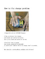
Eyepiece tube
Head of microscope
Arm
Objective turret
(nosepiece)
Objective lens
Linked single control
stage clips
Condenser lens
Stage
Illuminator field
lens housing
Base
Tension adjustment
Coarse focus
knob
Fine focus knob
Rheostat control
Safety rack stop
set screw
Disc
diaphragm
Eyepiece
locking screw
On/Off Switch
Recharging socket
Eyepiece
(ocular lens)
Camera housing

3
For optimum viewing satisfaction, follow these simple procedures. Nomenclature used to describe components and
controls can be identified by referring to the diagram at left.
UNPACKING
1. Carefully remove microscope, WF10x eyepiece, dustcover, 2mm “L” hex wrench (for rack stop adjustment), 0.90mm
“L” hex key wrench (for eyepiece socket set screw and for lamp replacement), USB Cord, microscope power adapter
(4.5v), USB power adapter (5V), and calibration slide. Always handle and move microscope by securely holding the
arm of microscope. Avoid touching any of the lens surfaces while handling the microscope. Dust, dirt, or fingerprints
can damage the delicate lens surfaces or adversely affect image quality.
2. Examine packing material before you discard it. Retain the styrofoam container in case you need to transport,
store, or return the microscope for service. If it becomes necessary to ship the microscope for any reason, pack it
in the styrofoam container, and then pack the styrofoam in another corrugated shipping container for optimum
protection. Use of the styrofoam alone will not provide adequate protection in transit, and will void your warranty.
MOTICONNECT APP DOWNLOAD
1. In preparation for using the DCX-205-RLED, you may wish to download and install the free MotiConnect app. The
MotiConnect app can be downloaded from either the Google Play Store or Apple App Store, depending on whether
you are using an Android or Apple device.
2. Instructions for the MotiConnect app can be found within the application through help button. Further instruction
available from Motic and National Optical YouTube pages online.
3. Your WiFi camera also has built in software, which is accessible by typing in the cameras IP address in your web
browser. These instructions are covered in WiFi Camera Operation section of this manual.
4. If you would like to connect the WiFi camera to a wireless enabled laptop or computer, go to the National Optical
website. On the website, you will need to register your product first and then you will be able to download the Motic
Images software. Instructions on connecting to your wireless enabled laptop or desktop are covered in the Wifi
Camera Operation section of this manual.
DESCRIPTION OF COMPONENTS
1. EYEPIECE (ocular lens) Lens closest to the eye, magnifies the primary image formed by the objective lens. The
eyepiece is equipped with a “pointer” that rotates as the eyepiece is turned.
2. OBJECTIVE TURRET (nosepiece) Revolving turret which holds objective lenses, permits changes of magnification
by rotating different powered objective lenses into optical path.
3. OBJECTIVE LENS Lens closest to the object being viewed, forms first magnified image of the specimen.
4. STAGE CLIPS Two linked single control locked-on clips hold specimen slide in place on stage.
5. STAGE Floating platform of the microscope where the specimen slide is placed.
6. CONDENSER LENS A specially designed condenser lens, fixed in center of stage, condenses light rays from
substage illumination and fills the back lens element of objective lens to improve image resolution.
7. DISC DIAPHRAGM Rotating disc located below stage with holes of various apertures, designed to help achieve
optimum resolution of the objective lens. Larger apertures used for higher magnifications, and smaller apertures used
for lower magnifications.
8. SAFETY RACK STOP When properly adjusted, it controls maximum upward travel of stage. Prevents higher power
objectives from breaking specimen slides, prevents damage to objective lenses. This stop has been pre-adjusted at
the factory.
9. FOCUSING KNOBS Coarse focusing knobs (larger knobs) located on each side of arm, raise or lower stage to
bring specimen image into focus. Fine focus knobs (smaller knobs) located on each side of arm permit more precise
image adjustment.

4
10. ILLUMINATION Built-in substage electric LED illuminator provides constant, reliable, pre-focused illumination equal
to a 20-watt tungsten bulb.
11. CAMERA HOUSING Built-in WiFi camera with USB port on back for powering camera only.
ASSEMBLY
Loosen 0.90mm socket set screw located in eyepiece tube and remove eyepiece dust cap. Insert WF10x eyepiece into
eyepiece tube and tighten 0.90mm socket screw to prevent removal of eyepiece.
MICROSCOPE OPERATION
1. Place microscope directly in front of you in a manner which permits you to comfortably look into the eyepiece. Note
that the head of microscope rotates 360º, permitting you to operate the microscope from the front or from the back,
whichever is most convenient for you. It also permits convenient sharing of microscope by more than one user, by
simply rotating head, without needing to move entire microscope.
2. Assure that light is available for illuminating the specimen.
a. Your microscope has special LED illumination that is powered by 3 rechargeable AA nickel metal hydride
batteries (supplied). These batteries may be recharged, as required, using the recharger (supplied). Each set of
batteries may be recharged approximately 500 times before replacing, and each charge will provide up to 50
hours of microscope operation. The LED component (bulb) will last for up to 50,000 hours before replacement is
required.
WARNING
DO NOT USE regular AA alkaline batteries. Use of other than rechargeable AA nickel metal hydride
batteries could result in batteries exploding during recharge. ONLY USE THE SUPPLIED SWITCHING
BATTERY RECHARGER WITH AUTOMATIC “TRICKLE CHARGE”.
b. It is recommended that you charge the batteries before initial use and after prolonged storage as the batteries
may have discharged. Plug output cord from battery charger into DC recharging socket located on back of
microscope base. Your automatic switching recharger operates on 100 to 240 volts AC 50/60 Hz. Plug recharger
into your AC wall outlet. Battery recharger is also equipped with an automatic “trickle charge” feature, the red
LED indicator lamp located on recharger will be illuminated when batteries are receiving maximum charge. After
batteries are charged, the red LED indicator lamp will turn to green and charger automatically switches to “trickle
charge”. The charger can be left plugged in, but for safety reasons it is a good idea to disconnect the charger
from the AC wall outlet and the output cord from recharging socket after 12 hours. Batteries and charger may feel
warm when charging, and unplugging the recharger is a safety precaution.
Note that your microscope can be used during recharging. Simply turn “on/off” switch on back of
microscope base to “on” position and proceed as follows.
c. In case of equipment malfunction, see troubleshooting procedures located at the back of this manual.
3. Rotate coarse focus knobs to move stage down (away) from objective lens as far as possible.
4. Place specimen slide, cover slip facing up, on stage with specimen centered over condenser lens in middle of stage.
5. Turn rheostat (dimmer) control in direction to reduce illumination brightness to about mid-point. Normally, brightness
will need to be reduced as magnification is reduced, and increased as magnification is increased. Experiment with
this adjustment until optimum resolution and contrast of specimen is obtained.
6. Rotate disc diaphragm until largest aperture is positioned beneath condenser in center of stage.
7. Turn the objective turret until the 4x (smallest) objective lens “clicks” into position in the optical path. Note that each
time you change from one objective lens to another you should turn the turret until you hear the “click”, which
indicates that the lens is properly indexed in the optical path.
8. While looking through the eyepiece, rotate coarse focusing knobs until specimen comes into focus. If image does not
appear in field of view, move specimen slide slightly until image appears in field of view.

5
9. Adjust fine focus controls until specimen is in sharp focus.
10. Changing magnification.
a. Magnification is changed by rotating objective turret until a different objective lens is moved into optical path.
Always turn turret until you hear the “click”, indicating that lens is properly indexed. Otherwise, you will not be
able to see anything when looking through the microscope.
b. Standard lenses provided with your microscope are a widefield 10x eyepiece, 4x, 10x, and 40x objectives. See
chart below for specifications on objectives.
Objective Specification Chart
Objective
N.A.
Color Code
Ring
Field of
View
Working
Distance
Magnification with
WF10X eyepiece
4X
0.10
Red
4.5mm
10.3mm
40X
10X
0.25
Yellow
1.8mm
8.5mm
100X
40X retractable
0.65
Blue
0.45mm
0.5mm
400X
c. Also note that each objective has a color ring, which permits you to instruct changes in magnification by referring
to an easily observed color rather than to a number.
d. The microscope has been parfocalled at the factory, which allows easy change from one magnification to another,
requiring little or no adjustment of the fine focus knobs.
e. As magnification is increased, the field of view (area of specimen seen through the microscope) will decrease.
That is why it is easier to find the specific area of interest on the specimen by starting with the lowest 4x objective
lens, before increasing magnification with the 10x or 40x objective lens.
f. NOTE: Care must be taken when rotating the 40x objective into place. This lens has a spring retractable
mechanism which retracts slightly into its housing if the front of the lens strikes the specimen slide. With fine
focus adjustment at mid-range, the rack stop has been adjusted at the factory to assure the 40x lens will clear the
thickness of a normal specimen slide and cover slip. However, if the rack stop has been improperly adjusted, or if
using a thicker than normal slide or cover slip, moving the 40x lens too quickly or carelessly could cause damage
to the front lens element or to the slide.
g. Do not let the front lens element come into contact with a wet slide surface, as prolonged contact with any
moisture could damage the lens. If lens is exposed to moisture, promptly wipe with soft tissue to remove
moisture.
WIFI CAMERA OPERATION
1. Powering the WiFi camera
a. The built-in WiFi camera is powered through the USB port located behind the camera housing of the microscope.
Supplied with your microscope is a USB (5V) wall plug power adapter and USB cable. First plug the adapter into
the A/C wall power outlet. Then insert the flat end of the USB cord into the adapter and the other square end into
the USB port behind the camera housing.
b. As power is being established, you will notice a blue LED flashing, located in front of the camera housing. Once
the blue LED remains solid, the WiFi camera is ready to be used.
2. Connecting to Android or Apple device
a. The built-in WiFi camera in this unit performs much like a wireless router. You will first need to locate the wireless
signal with your Android or Apple device. This is usually done through the settings feature of your device (please
refer to your devices manual for further instructions). Once you have located the signal (usually labeled MC-WiFi-
….), you will need to connect using the default password of 12345678. This cannot be changed except by the
factory. Any attempt to do so will render your WiFi camera inoperable and will void your warranty.
b. Once the connection has been established, you can begin using the WiFi camera through the MotiConnect App
(automatic) or through your web browser, using the following address:
http://192.168.1.151:8080.

6
c. For further help and instructions on using MotiConnect, please visit both the Motic and National Optical YouTube
pages.
3. Connecting to wireless enabled laptop or desktop
a. You will first need to locate the wireless signal, the same way you would connect to any wireless router or signal.
Once you have located the signal (usually labeled MC-WiFi-….), you will need to connect using the default
password of 12345678. This cannot be changed except by the factory. Any attempt to do so will render your
WiFi camera inoperable and will void your warranty.
b. Once connected, open your Motic Images software. If you are using a Windows based system, click on the
capture button. This will open the Live Imaging Module. Locate the Video Device box. You will notice that by
default the Moticam X is selected. Click on the Open button and the software will enable the camera. If you are
using an Apple based system, click on File at the top of the Motic Images tool bar. Select Capture or New and
then Live Video, to enable the camera. Instructions on the Motic Images software are covered within the software
under Help. You may also visit both the Motic and National Optical YouTube pages.
MAINTENANCE
WARNING: For your own safety, turn switch to OFF position and remove electrical plug from power source.
1. OPTICAL MAINTENANCE
Do not attempt to disassemble any lens components. Consult a microscope service technician when any repairs not
covered by instructions are needed.
Prior to cleaning any lens surface, brush dust or dirt off lens surfaces using a camel hair brush or use air to blow dust
and lint off surfaces. Use of compressed air in a can, available at any computer supply store, is a good source of
clean air.
Do not remove eyepieces or objective lenses to clean. Clean only the outer lens surface. Breath on lens to dampen
surface, then wipe with lens paper or tissue or use a cotton swab moistened with distilled water. Wipe lenses with a
circular motion, applying as little pressure as possible. Avoid wiping dry lens surface as lenses are scratched easily.
If excessive dirt or grease gets on lens surfaces, a small amount of Windex can be used on a cotton swab or lens
tissue. To clean objective lenses, do not remove objectives from microscope. Clean front lens element only,
following same procedure.
NOTE: Fingerprints or other matter on the front lens element of the objective lens is the single most common
reason that you will have difficulty in focusing the microscope. Before having costly servicing done, or
before returning to National for “warranty repair”, make certain to examine the front lens element with a
magnifying glass or eye loupe for the presence of such contaminants. If a microscope is returned to National
for warranty repair, and it is determined that such contaminants are the problem, this is not covered under
warranty and National will submit a cost estimate for cleaning.
2. MECHANICAL MAINTENANCE
a. The rack stop screw has been pre-adjusted at the factory and should not require re-adjustment. However, if you
do attempt re-adjustment, note the following procedure.
Using a 2mm “L” type hex key wrench, loosen rack stop hex socket set screw by rotating in a counterclockwise
direction. With fine focus adjustment at mid-range, focus on a standard slide until sharp image is obtained.
Rotate rack stop screw in clockwise direction until tight
b. Coarse focus tension adjustment prevents the stage from drifting down from its own weight and causing the
image to move out of focus. This has been adjusted at the factory, but over the course of time it may loosen and
cause the stage of the microscope to slip downward on the focusing block.
With stage facing you, the tension adjustment collar is located between arm and coarse focus knob on right side
of microscope. With 0.9mm “L” type key wrench, loosen the set screw located in the hole on tension adjustment
collar, turn collar clockwise to tighten tension, counter-clockwise to loosen tension. Use of a wide rubber band will
provide a better grip on the tension adjustment collar. After adjusting, tighten the set screw to lock adjustment
collar in place.

7
NOTE: It is recommended that you leave the tension as loose as possible for ease of focusing, yet not so loose
that it permits the stage of microscope to drift downward from its own weight and cause the microscope to “drift”
out of focus.
c. Metal parts: Use a clean, damp cloth to remove dust or dirt from metal parts, followed by a dry cloth.
3. ELECTRICAL MAINTENANCE
The extent of electrical maintenance, by other than a qualified technician, should be LED replacement, battery
recharging and battery replacement. Before maintenance, be sure that recharger is not connected to microscope.
a. Recharging batteries:
Plug output cord from battery charger into DC recharging socket located on back of microscope base. Your
automatic switching recharger operates on 100 to 240 volts AC 50/60 Hz, plug recharger into your AC wall outlet.
The red LED indicator lamp located on recharger will be illuminated when batteries are receiving maximum
charge. After batteries are charged, the red LED indicator lamp will turn to green and charger automatically
switches to “trickle charge”. The charger can be left plugged in, but for safety reasons it is a good idea to
disconnect the charger from the AC wall outlet and the output cord from recharging socket after 12 hours.
Batteries and charger may feel warm when charging, and unplugging the recharger is a safety precaution.
You may operate the microscope light even while it is being recharged. Simply flip light switch to “on” position
and continue using microscope while the recharger is fully engaged.
b. Replacing batteries:
Your microscope includes 3 rechargeable AA nickel metal hydride batteries. These may be recharged up to 500
times, but if you observe that a recharge is providing significantly less than 40 hours of operation. It is probably
time to replace to batteries.
IMPORTANT WARNING: DO NOT USE REGULAR ALKALINE BATTERIES IN THIS MICROSCOPE. ANY
ATTEMPT TO RECHARGE ALKALINE TYPE BATTERIES COULD RESULT IN BATTERIES EXPLODING.
Gently lay microscope on its side or back. Observe door at front of microscope bottom base. Loosen slotted
screw on door and open. Battery case is mounted on inside of door. Using small Phillips screwdriver, carefully
remove Phillips screw that holds battery case together. Slide lid of case straight out to remove and expose
batteries. Remove all 3 batteries and replace with new rechargeable AA nickel metal hydride batteries, making
certain to insert with correct polarity according to markings on battery holder. Replace lid, close and secure door.
Follow instructions on new battery packaging to determine if they are already charged, or if they should be
charged before initial use. If recharging is required, following directions in “3.a” above.
c. Replacing LED element:
An LED “bulb” will last up to 50,000 hours, so you don’t have to do this exercise very often.
To open the illuminator field lens housing, use 0.9mm “L” type hex key wrench supplied with your microscope.
Loosen hex screws on lens housing. Remove lens housing to expose LED “bulb.” Remove bulb by grasping the
plastic base of bulb and gently pulling straight up. Insert new LED “bulb”, replace lens housing and tighten hex
screws to secure lens housing in place.

8
TROUBLESHOOTING
PROBLEM
REASON FOR PROBLEM
SOLUTION
Light fails to operate.
Batteries fully discharged.
Recharge batteries.
Rheostat control not turned far
enough.
Turn rheostat to increase light
Intensity.
Light switch in “off” position.
Turn light switch “on”.
LED “bulb” burned out.
Replace LED “bulb”.
Image does not remain in focus
Stage of microscope drops from
its own weight.
Adjust tension control.
Image will not focus
Rack stop not set at proper
position.
Adjust rack stop.
Slide upside down.
Place slide on stage with cover
slip up.
Slide cover slip too thick.
Use 0.17mm thick cover slip
(No.1 cover slip)
Poor resolution
(image not sharp)
Objective lenses dirty.
Clean objective lenses.
Eyepiece lens dirty.
Clean eyepiece lenses.
Too much light.
Adjust diaphragm.
Spots in field of view.
Eyepiece or condenser lens dirty.
Clean lens. ***
Specimen slide dirty.
Clean slide.
No WiFi signal
No power to the camera.
Make sure blue LED is solid
Make sure camera power
adapter is plugged in.
Make sure the USB plug is
seated properly in the head and
power adapter.
Cannot connect to WiFi camera
Password entered incorrectly.
IP address entered incorrectly.
Default Password: 12345678.
Default IP: 192.168.1.151:8080.
***Spots in field of view can also result from dirt on inside of eyepiece. It is recommended that you have
service technician clean inside of lens.
OPTIONAL ACCESSORIES AND PARTS:
#800-001 Replacement LED light
#802-003 Auto cut-off recharger for rechargeable LED microscope
#951 Dustcover, 16” tall x 13”, heavy vinyl with stitched seams.
WARRANTY
Please see our website,
www.nationaloptical.com, for complete warranty details and exclusions.
/