Page is loading ...

Service Manual
w/CON•X•US Interface
Models:
2500 - 5000
This manual must only be used
by a qualified heating installer
/ service technician. Read
all instructions, including
this manual and the Crest
Installation and Operation
Manual, before installing.
Perform steps in the order
given. Failure to comply could
result in severe personal injury,
death, or substantial property
damage.
WARNING
Save this manual for future reference.
FB-SER_100161013_2000004598 Rev M

2
Hazard definitions
The following defined terms are used throughout this manual to bring attention to the presence of hazards of various risk levels or
to important information concerning the life of the product.
DANGER
WARNING
CAUTION
CAUTION
NOTICE
DANGER indicates an imminently hazardous situation which, if not avoided, will result in death or serious
injury.
WARNING indicates a potentially hazardous situation which, if not avoided, could result in death or serious
injury.
CAUTION indicates a potentially hazardous situation which, if not avoided, may result in minor or moderate
injury.
CAUTION used without the safety alert symbol indicates a potentially hazardous situation which, if not
avoided, may result in property damage.
NOTICE indicates special instructions on installation, operation, or maintenance that are important but not
related to personal injury or property damage.
CONTENTS ........................................................................ 2
Hazard Definitions .............................................................. 2
PLEASE READ BEFORE PROCEEDING ........................ 3
Handling Ceramic Fiber Materials ...................................... 3
When servicing boiler ................................................... 4
Boiler operation ............................................................ 4
Boiler water ................................................................... 4
Freeze protection fluids ................................................ 4
WHAT IS IN THIS MANUAL .............................................. 5
1. SERVICE
Boiler Piping ....................................................................... 6
SMART TOUCH w/CON•X•US Interface ........................... 7
General Operation ......................................................... 8
Control Inputs ............................................................... 9
Control Outputs ........................................................... 10
Table 1A - Sequence of Operation .................................. 11
Initial Setup Screen ........................................................... 12
Viewable and Changeable Control Parameters ............... 13
Set Point Screens .................................................. 13-15
Outdoor Reset Screen ........................................... 16-17
Ramp Delay Screen .............................................. 18-19
BMS Screens .......................................................... 20-22
Advanced Setup Screen .........................................23-24
Night Setback Screen ................................................... 25
Pump Screen ...........................................................26-27
Cascade Screens .................................................... 28-30
Service Screen.........................................................31-32
Graph Screens .............................................................. 33
History Screens........................................................34-35
2. MAINTENANCE
Maintenance and Annual Startup ................................ 36-40
3. TROUBLESHOOTING
Before Troubleshooting .................................................... 41
Check Control Module Fuses .......................................... 41
Table 3A - Troubleshooting Chart - No Display ............... 42
Checking Temperature Sensors ...................................... 43
Table 3F - Troubleshooting Chart - Noisy System .......... 44
Table 3G - Troubleshooting Chart - Fault Messages . 45-56
Combustion Analysis Procedure ................................. 57-58
Table 3H - Flue Products ................................................. 57
Table 3I - Troubleshooting Chart - Combustion Levels . 58
Gas Valve Adjustment Procedure .................................... 59
Revision Notes .................................................. Back Cover
Contents

Service Manual
Please read before proceeding
Installer – Read all instructions, including
this manual and the Crest Installation
and Operation Manual, before installing.
Perform steps in the order given.
User – This manual is for use only by
a qualified heating installer/service
technician. Refer to the Crest User’s
Information Manual for your reference.
Have this boiler serviced/inspected by
a qualified service technician at least
annually.
Failure to comply with the above could
result in severe personal injury, death or
substantial property damage.
When calling or writing about the boiler
– Please have the boiler model and serial
number from the boiler rating plate.
Consider piping and installation when
determining boiler location (see the Crest
Installation and Operation Manual).
Any claims for damage or shortage in
shipment must be filed immediately
against the transportation company by the
consignee.
3
Handling ceramic fiber materials
REMOVAL OF COMBUSTION CHAMBER LINING
The combustion chamber insulation in this appliance contains ceramic fiber material. Ceramic fibers can
be converted to cristobalite in very high temperature applications. The International Agency for Research
on Cancer (IARC) has concluded, “Crystalline silica in the form of quartz or cristobalite from occupational
sources is carcinogenic to humans (Group 1).” Normal operating temperatures in this appliance are below
the level to convert ceramic fibers to cristobalite. Abnormal operating conditions would have to be created
to convert the ceramic fibers in this appliance to cristobalite.
The ceramic fiber material used in this appliance is an irritant; when handling or replacing the ceramic
materials it is advisable that the installer follow these safety guidelines.
Avoid breathing dust and contact with skin and eyes.
• Use NIOSH certified dust respirator (N95). This type of respirator is based on the OSHA
requirements for cristobalite at the time this document was written. Other types of respirators may
be needed depending on the job site conditions. Current NIOSH recommendations can be found on
the NIOSH website at http://www.cdc.gov/niosh/homepage.html. NIOSH approved respirators,
manufacturers, and phone numbers are also listed on this website.
• Wear long-sleeved, loose fitting clothing, gloves, and eye protection.
Apply enough water to the combustion chamber lining to prevent airborne dust.
Remove the combustion chamber lining from the appliance and place it in a plastic bag for disposal.
Wash potentially contaminated clothes separately from other clothing. Rinse clothes washer
thoroughly.
NIOSH stated First Aid.
Eye: Irrigate immediately.
Breathing: Fresh air.
WARNING
NOTICE
WARNING

4
Service Manual
Please read before proceeding
When servicing boiler –
• To avoid electric shock, disconnect electrical supply
before performing maintenance.
• To avoid severe burns, allow boiler to cool before
performing maintenance.
Boiler operation –
• Do not block flow of combustion or ventilation air to
the boiler.
• Should overheating occur or gas supply fail to shut off,
do not turn off or disconnect electrical supply to
circulator. Instead, shut off the gas supply at a location
external to the appliance.
• Do not use this boiler if any part has been under water.
The possible damage to a flooded appliance can be
extensive and present numerous safety hazards. Any
appliance that has been under water must be replaced.
Boiler water –
• Thoroughly flush the system (without boiler
connected) to remove sediment. The high-efficiency
heat exchanger can be damaged by build-up or
corrosion due to sediment.
• Do not use petroleum-based cleaning or sealing
compounds in the boiler system. Gaskets and seals in
the system may be damaged. This can result in
substantial property damage.
• Do not use “homemade cures” or “boiler patent
medicines”. Serious damage to the boiler, personnel,
and/or property may result.
• Continual fresh make-up water will reduce boiler life.
Mineral buildup in the heat exchanger reduces heat
transfer, overheats the stainless steel heat exchanger, and
causes failure. Addition of oxygen carried in by makeup
water can cause internal corrosion. Leaks in boiler
piping must be repaired at once to prevent the
introduction of makeup water.
Freeze protection fluids –
• NEVER use automotive antifreeze. Use only inhibited
propylene glycol solutions which are specifically
formulated for hydronic systems. Ethylene glycol is
toxic and can attack gaskets and seals used in hydronic
systems.

Service Manual
5
What is in this manual?
Service
Near boiler piping
• Typical system components
The Crest boiler display
• Display panel readout, buttons and their functions
Control module inputs
• Control module inputs and options
Control module outputs
• Control module outputs and options
General
• How the boiler operates
• How the control module operates
• Access modes -- user and installer
• Sequence of operation -- HW/space heating
Control panel menu access
• Accessing programming mode and locating menus
(See separate guide covering the PC interface.)
Control panel parameter access
• Accessing and changing parameters from the display panel
Quick start information -- parameter
table
• An index of available adjustments and readouts, where to
access them and where to find detailed information.
Crest boiler operation
• Initial Setup
• Set Points
• Outdoor Reset
• Ramp Delay
• BMS
• Advanced Setup
• SH Night Setback
• HW Night Setback
• Cascade
• Pumps
• Service Notification
Maintenance
• Service and maintenance schedules
• Address reported problems
• Inspect boiler area and boiler interior
• Clean condensate trap
• Check all piping for leaks
• Check air openings
• Flue vent system and air piping
• Check water system
• Check expansion tank
• Check boiler relief valve
• Inspect ignition electrode
• Check ignition ground wiring
• Check all boiler wiring
• Check control settings
• Perform start-up and checks
• Check burner flame
• Check flame signal
• Check flue gas temperature
• General maintenance
• Review with owner
• Cleaning boiler heat exchanger
• Oiled bearing circulators
Troubleshooting
• Troubleshooting table - No display
• Checking temperature sensors
• Sensor tables
• Troubleshooting table - Fault messages displayed on
boiler interface
• Combustion analysis procedure
• Gas valve adjustment procedure

1 Service
6
Service Manual
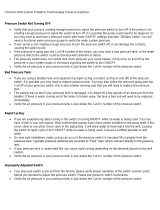
Boiler piping
This piping reference is included to specify the Boiler Piping specific to the Crest boiler. This piping scheme is important for
proper operation of the SMART TOUCH control. See the Crest Installation and Operation Manual for more detailed piping
diagrams.
Single Boiler - Recommended - Primary / Secondary Piping with a Hot Water Generator
HOT WATER
GENERATOR
WATER
GENERATOR
CIRCULATOR
BOILER PUMP
FLOW CHECK
VALVE (TYPICAL)
Y-STRAINER
(RECOMMENDED)
RELIEF
VALVE
BALL VALVE
(TYPICAL)
AIR SEPERATOR
DRAIN PORT
(TYPICAL)
SYSTEM
CIRCULATOR
BACK FLOW
PREVENTER
PRESSURE
REDUCING VALVE
PRESSURE
GAUGE
EXPANSION
TANK
12"
MAX
FROM SYSTEM
TO SYSTEM
MAKE UP
WATER
BOILER
DRAIN
SYSTEM RETURN
SENSOR
SYSTEM SUPPLY
SENSOR
Y-STRAINER
(RECOMMENDED)
RELIEF
VALVE
BALL VALVE
(TYPICAL)
AIR SEPERATOR
DRAIN PORT
(TYPICAL)
SYSTEM
CIRCULATOR
BACK FLOW
PREVENTER
PRESSURE
REDUCING VALVE
PRESSURE
GAUGE
EXPANSION
TANK
FROM SYSTEM
TO SYSTEM
MAKE UP
WATER
BOILER DRAIN
Single Boiler - Alternate - Full Flow System Piping

Service Manual
7
1 Service (continued)
The Home Screen displays status, modulation rate, outlet water temperature, inlet water temperature, flue temperature, system
supply temperature, system return temperature, outdoor air temperature, and domestic hot water tank temperature.
The boiler can be started and stopped by pressing the ON/OFF button. The Boiler Status Screen and Main Menu Screen can be
accessed by pressing the appropriate button.
Figure 1-1 Home Screen
Outlet Water Temperature - This is the boiler outlet
temperature.
Inlet Water Temperature - This is the boiler inlet temperature.
System Supply Temperature - This is the water temperature
as measured by the system supply sensor located in the
downstream piping (if connected).
System Return Temperature - This is the water temperature
measured by the system return sensor located in the upstream
piping (if connected).
When the ON/OFF switch is turned to the ON position,
the first screen visible on the LCD display will be the Home
Screen. This screen displays the current status of the Crest
boiler. The following items can be viewed or interacted with
on the Home Screen:
On/Off button - Pressing this button allows the boiler to be
placed in either Manual Shutdown Mode or Standby Mode.
Status - This line shows the current operating status of the
Crest boiler and the current set point.
Outside Air Temperature - This is the outdoor air temperature
(if connected).
HW Temperature - This is the temperature as measured by the
tank sensor in the hot water storage tank (if connected).
Flue Temperature - Temperature measured by the flue sensor.
Time - The time is displayed in the lower left-hand corner
of the display. Reference this manual for Night Setback
parameters and more information regarding adjusting the date
and time.
Modulation Percentage - Displays the current boiler firing
rate.
w/CON•X•US Interface

1 Service
8
Service Manual
General Operation
How the boiler operates
The Crest uses an advanced stainless steel heat exchanger
and electronic control module that allows fully condensing
operation. The blowers pull in air and push flue products out
of the boiler through the heat exchanger and flue piping. The
control module regulates blower speeds to control the boiler
firing rate. The gas valves sense the amount of air flowing into
the boiler and allow only the right amount of gas to flow.
How the control modules operate
The Crest boiler is equipped with a SMART TOUCH CON•X•US
Interface. The control module receives inputs from boiler
sensors and external devices. The control module activates and
controls the blowers and gas valves to regulate heat input and
switches the boiler, Hot Water Generator (HW), and system
pumps on and off as needed. The user programs the control
module to meet system needs by adjusting control parameters
through the SMART TOUCH CON•X•US Interface. These
parameters set operating temperatures and boiler operating
modes.
Sequence of operation
Table 1A (page 11) shows control module normal sequences of
operation for space heating and HW operation. The combined
operation sequence is for a typical application, programmed to
provide HW priority.
Access modes
User
The USER can set the SH set point, HW set point, turn the unit
OFF and ON and set up WiFi.
Installer
Most parameters are available only to the INSTALLER,
accessible only by entering the installer password (5309) when
selecting the Setup Section.
Note: The password will timeout after an hour from entry.

1 Service
9
Service Manual
1 Service (continued)
GAS PRESSURE SWITCHES
HWG THERMOSTAT /
SENSOR
ENABLING DEVICE
SYSTEM SENSOR -
SUPPLY
OUTDOOR SENSOR
SEQUENCER / BUILDING
MANAGEMENT SYSTEM
LOW VOLTAGE
CONNECTION
BOARD
INLET TEMPERATURE
SENSOR
OUTLET TEMPERATURE /
HI-LIMIT SENSOR
FLUE GAS SENSOR
LOUVER PROVING SWITCH
FLAME SENSOR 1 & 2
LOW WATER CUTOFF
BLOCKED DRAIN SWITCH
DISPLAY PANEL
PC INTERFACE
SMART CONTROL
MODULE
AIR PRESSURE SWITCH
SYSTEM SENSOR -
RETURN
AUX SWITCH 1 & 2
0-10 INPUT FROM
SYSTEM PUMP
BLOWER PROVING
SWITCHES
CASCADE
INLET AIR SENSORS
MANUAL RESET
HIGH LIMIT
VENT DAMPER
PROVING SWITCH
BAS BOARD
Control inputs

1 Service
Service Manual
10
1 Service
LOW VOLTAGE
CONNECTION
BOARD
SMART CONTROL
MODULE
ALARM CONTACTS
LOUVER RELAY
RUN TIME CONTACTS
SEQUENCER / BUILDING
MANAGEMENT SYSTEM
BOILER PUMP
CONTACTOR
SYSTEM PUMP
CONTACTOR
HWG PUMP
CONTACTOR
IGNITOR
BLOWERS
GAS VALVES
BOILER RATE OUTPUT
DISPLAY PANEL
PC INTERFACE
120V
SUPPLY
SYSTEM PUMP BOILER PUMP DHW PUMP
MAX. 1.5 AMPS PER CONNECTION
NL
FIELD SUPPLI ED CONTACTOR MUS T
BE INSTALLED
LINE VOLTAGE
TERMINAL
STRIP
0-10V OUTPUT TO
BOILER PUMP
VENT DAMPER
Control outputs

1 Service (continued)
11
Service Manual
Table 1A Sequence of Operation
Sequence of operation
1.
Upon a call for heat, the control turns on the appropriate pumps (system and boiler pumps for a space heating call,
HW pump for a hot water generator call).
2.
The control confirms that the low water cutoff contacts are closed and energizes the louvers (optional) and damper
(optional) relays.
3.
The control confirms that the gas pressure switch, blocked drain switch, limits, louver proving switch (optional) and
damper proving switch (optional) contacts close. The Pre-Purge cycle begins.
4.
The control confirms both blowers come up to the desired speed, both blower proving switches close, and the air
pressure switch is closed.
5.
Once the Pre-Purge cycle is complete, the control lowers the blower speeds, initiates sparking of the ignition
electrode, and opens Gas Valve 1.
6.
After a short wait, the control stops sparking and checks for the presence of flame current through the flame sense
electrode.
7.
If the control does not detect flame current, the control will lockout indefinitely, until the RESET button on the touch
screen LCD is pressed. Model FB 2500 will have one retry.
8.
If the control detects flame current, the control will hold the blower speed constant for a few seconds to allow the
flame to stabilize, then begin modulating the firing rate in order to maintain the controlling sensor to the desired set
point temperature.
9.
If the current call for heat is for space heating and a HW call for heat becomes active, the control will turn on the HW
pump relay output, then turn off the boiler pump. It will then modulate the blower speed in order to maintain the
outlet temperature to the desired HW outlet set point temperature.
10.
If the first combustion system in the boiler is unable to maintain the desired set point temperature, the second
combustion system in the boiler will be started. Both blowers will modulate to a set speed, and the second gas valve
will be energized. The second combustion system will light from the first combustion system. The second flame will
be monitored much like the first. Once both combustion systems are firing, the control will work in synchronization
to maintain the desired set point temperature. If the heat load should decrease sufficiently, the second combustion
system will be shut down.
11.
Once both the space heating and HW calls for heat are satisfied, the control will turn off the gas valve(s) and begin
the Post-Purge cycle. Any pumps that are running will begin their respective Pump Delay cycles.
12.
At the end of the Post-Purge cycle, the louver relay contacts will de-energize.
13.
The control verifies that the blowers stop running and the blower proving switches open.
14.
At the end of the Pump Delay cycle(s), the pump(s) will be turned off.
Note: This unit is equipped with two (2) gas train systems. Gas Train 1 will fire first. If the demand cannot be met by the first
gas train, the second gas train (Gas Train 2) will fire.

1 Service
12
Service Manual
Initial Setup Screen
Figure 1-2 Rapid Setup A
Initial Setup
Clock and Date
The control uses an internal clock for the night setback
feature and for logging of events. For these features to
work correctly, the clock must be set when the boiler is first
installed or anytime the boiler has been powered off for more
than four (4) hours. This parameter must be accessed to set
the clock. If the unit is connected to the internet, the time will
adjust based on the time zone selected.
Temperature units (°C / °F)
The control can be configured to display temperature in
either °C or °F.

1 Service (continued)
Service Manual
13
Viewable and changeable control parameters
CAUTION
Before changing parameters, note the settings so that the unit can be returned to its original operating
parameters.
Figure 1-3 Set points HW_Screen A
Figure 1-4 Set points HW_Screen B
Set Point Screens

Menu
Parameter Name
(as shown on the LCD screen)
Min
Max
Default
Value Value Value
Space Heat 1 Set point: Set point 32 185 120
Space Heat 1 Set point: Min 32 185 32
Space Heat 1 Set point: Max 32 185 185
Space Heat 1 Set point: Offset 0 36 9.9
Space Heat 1 Set point: Diff 0 72 19.8
System Pump Anti-Seize Time 0 40 0.33
High Limit: ARHL 32 200 199.4
High Limit: MRHL 0 90 0
HW Boiler Set point: Set point N/A N/A N/A
HW Boiler Set point: Offset N/A N/A N/A
HW Boiler Set point: Differential N/A N/A N/A
HW Tank Set point: Set point N/A N/A N/A
HW Tank Set point: Min N/A N/A N/A
HW Tank Set point: Max N/A N/A N/A
HW Tank Set point: Diff N/A N/A N/A
1 Service
Service Manual
14
Figure 1-5 Set points SH_Screen A
1 Service
SET POINTS
Table 1B Set Points (This table lists control module parameters; use the sub-tab under the Setup tab to access
them.)

1 Service (continued)
Service Manual
15
Set Points
Space Heat 1 Set Point: Set point
The SH set point sets the water temperature set point used
during space heating calls.
Space Heat 1 Set Point: Min
The SH minimum set point sets the minimum water
temperature set point that can be used for space heating
operation. The user or installer will not be able to
program the control with a lower SH set point.
Space Heat 1 Set Point: Max
The SH maximum set point sets the maximum water
temperature set point that can be used for space heating.
The user or installer will not be able to program the
control with a higher SH set point.
Space Heat 1 Set Point: Offset
The SH offset sets how many degrees above set point the
temperature can go before the boiler will shut off.
Space Heat 1 Set Point: Differential
The SH differential sets how many degrees below the
offset the temperature has to drop before the boiler turns
back on.
High Limit: ARHL
The SMART TOUCH control contains an integral Auto
Reset High Limit (ARHL) on the outlet of the heat
exchanger. Once the outlet temperature exceeds the
ARHL set point, the boiler will shut down and lock out.
Once the outlet temperature has dropped below this
set point, the RESET button on the LCD display can be
pressed to reset this lockout. If RESET is not pressed, the
control will automatically reset the lockout after five (5)
minutes.
High Limit: MRHL
The SMART TOUCH control contains an integral
Manual Reset High Limit (MRHL) on the outlet of the
heat exchanger. Once the outlet temperature exceeds
the MRHL set point, the boiler will shut down and lock
out. Once the outlet temperature has dropped below this
set point, the RESET button on the LCD display must be
pressed to clear this lockout.
HW Boiler Set Point: Set point
When a HW call for heat becomes active, the control will use
the HW boiler set point to determine the firing rate of the
boiler based on the boiler outlet water temperature.
HW Boiler Set Point: Offset
This parameter reflects the degrees above HW boiler set point
the outlet temperature can go before the boiler will shut off.
HW Boiler Set Point: Differential
This parameter reflects the degrees below HW boiler offset the
outlet temperature has to go before the boiler turns on.
HW Tank Set Point: Set Point
By installing a tank sensor, the SMART TOUCH control can
perform the tank thermostat function. The SMART TOUCH
control automatically detects the presence of this sensor, and
generates a call for heat when the tank temperature drops
below the tank set point minus the differential, and finishes the
call for heat when the tank temperature reaches tank set point.
HW Tank Set Point: Min
This setting controls the minimum user set point for the tank
temperature.
HW Tank Set Point: Max
This setting controls the maximum user set point for the tank
temperature.
HW Tank Set Point: Differential
When a tank sensor is installed, the tank temperature must
drop this amount below the tank set point before the boiler
will turn on.

Menu
Parameter Name
(as shown on the LCD screen)
Min
Max
Default
Value Value Value
Set point Max 32 185 180
Set point Min 32 185 68
Outdoor Temperature: Min -22 86 23
Outdoor Temperature: Max -22 86 86
Outdoor Temp: Shutdown 32 122 79.7
Outdoor Temp: Diff 32 122 79.7
Shift OA Reset Curve -27 27 0
Boost Time 0 250 20
Boost Temperature 0 25 0
1 Service
Service Manual
16
Outdoor Reset Screen
Figure 1-6 Outdoor Reset A
Table 1C Outdoor Reset (This table lists control module parameters; use the sub-tab under the Setup tab to access
them.)
OUTDOOR RESET

1 Service (continued)
Service Manual
17
Outdoor Reset
Outdoor Reset Curve
The Outdoor Temp Min and Set Point Max define the
upper point of the Outdoor Reset Curve. The lower point
is defined by the Outdoor Temp Max and Set Point Min.
The curve will level out at Set Point Min for temperature
warmer than Outdoor Temp Max. The curve will continue
on if the set point (set on Set Points Screen) is above the Set
Point Max. The curve will be shortened if the set point is
below Set Point Max.
Outdoor Temperature: Shutdown
When the outdoor temperature rises above this point, the
control will block all SH demands (HW demands will still
be active).
Outdoor Temperature: Differential
The outdoor air shutdown differential parameter is the
number of degrees below parameter the outdoor air
temperature must go before the boiler will respond to a SH
demand.
Shift OA Reset Curve
The shift reset curve parameter shifts the actual set point
above or below the calculated set point by the number of
degrees in this parameter.
Boost Time
The boost time parameter sets the amount of time that must
elapse with a SH demand before the water temperature
calculated set point will be increased.
Boost Temperature
If a SH demand lasts longer than the programmed boost time
delay setting and there have been no HW demands, the control
will increase the water temperature set point by the amount in
this parameter. If the SH demand continues through another
time period, the set point will be increased again. This will
continue until either the SH demand ends, a maximum of 20
increases has occurred, or the maximum set point has been
reached. Once the SH demand has been satisfied the set point
will revert back to its calculated setting.

18
Service Manual
1 Service
Ramp Delay Screen
Figure 1-7 Ramp Delay
Menu
Parameter Name
(as shown on the LCD screen)
Min
Max
Default
Value Value Value
Ramp Delay Mode N/A N/A N/A
Step 1: Ramp Delay Time 1 40 2
Step 1: Ramp Delay Limit (%) 10 100 20
Step 2: Ramp Delay Time 1 40 2
Step 2: Ramp Delay Limit (%) 10 100 30
Step 3: Ramp Delay Time 1 40 2
Step 3: Ramp Delay Limit (%) 10 100 40
Step 4: Ramp Delay Time 1 40 1
Step 4: Ramp Delay Limit (%) 10 100 55
Step 5: Ramp Delay Time 1 40 1
Step 5: Ramp Delay Limit (%) 10 100 75
Step 6: Ramp Delay Time 1 40 1
Step 6: Ramp Delay Limit (%) 10 100 100
Table 1D Ramp Delay (This table lists control module parameters; use the sub-tab under the Setup tab to access
them.)
RAMP DELAY

19
Service Manual
1 Service (continued)
Ramp Delay
Ramp Delay (Enable / Disable)
This parameter allows the installer to enable or disable the SH
ramp delay.
SH Ramp Delay
The SMART TOUCH CON•X•US Interface can be
programmed to limit the firing rate for a fixed period of time at
the start of a space heating demand. There are six (6) possible
limits, each with their own time delay. The first limit applies
as soon as the burner starts. Once its time delay expires, the
second limit is applied and its timer begins. The control steps
through these limits until the 6th (sixth) limit expires. Note,
however, that the 6th limit will also limit the rate for the rest of
that heat demand.

1 Service
Service Manual
20
BMS Screens
Figure 1-8 BMS_Screen A
Figure 1-9 BMS_Screen B
/