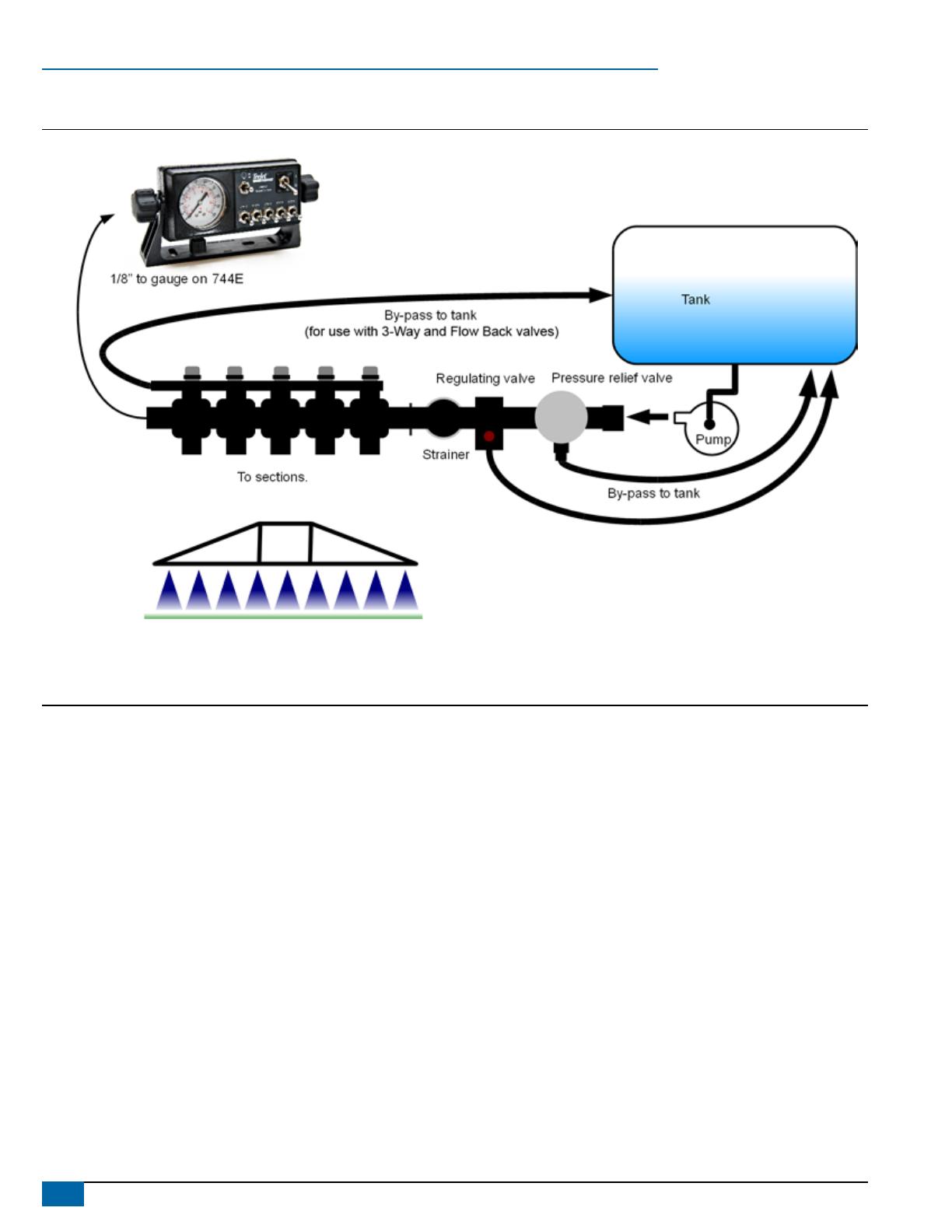
Smithco TeeJet® 744E User manual

Type
User manual

This manual is also suitable for

744E
SPRAYER CONTROL
USER MANUAL
Copyrights
© 2013 TeeJet Technologies. All rights reserved. No part of this document or the computer programs described in it may be reproduced, copied,
photocopied, translated, or reduced in any form or by any means, electronic or machine readable, recording or otherwise, without prior written
consent from TeeJet Technologies.
Trademarks
Unless otherwise noted, all other brand or product names are trademarks or registered trademarks of their respective companies or organizations.
Limitation of Liability
TEEJET TECHNOLOGIES PROVIDES THIS MATERIAL “AS IS” WITHOUT WARRANTY OF ANY KIND, EITHER EXPRESSED OR IMPLIED.
NO COPYRIGHT LIABILITY OR PATENT IS ASSUMED. IN NO EVENT SHALL TEEJET TECHNOLOGIES BE LIABLE FOR ANY LOSS OF
BUSINESS, LOSS OF PROFIT, LOSS OF USE OR DATA, INTERRUPTION OF BUSINESS, OR FOR INDIRECT, SPECIAL, INCIDENTAL, OR
CONSEQUENTIAL DAMAGES OF ANY KIND, EVEN IF TEEJET TECHNOLOGIES HAS BEEN ADVISED OF SUCH DAMAGES ARISING FROM
TEEJET TECHNOLOGIES SOFTWARE.
1
98-70030-ENUS R1
744E
Table of Contents
CHAPTER 1  INTRODUCTION 2
System Congurations ....................................................................................................................................................................................... 3
Plumbing Diagram ............................................................................................................................................................................................... 4
Kit Contents ............................................................................................................................................................................................................ 4
Control Housing Assembly ................................................................................................................................................................................ 6
CHAPTER 2  INSTALLATION 7
Mounting Bracket ................................................................................................................................................................................................. 7
Pressure Gauge ...................................................................................................................................................................................................... 7
Tube Assembly ...................................................................................................................................................................................................... 7
Connection to Manifold ..................................................................................................................................................................7
Connection to 744E Console .........................................................................................................................................................8
CHAPTER 3  MAINTENANCE 8
Routine Procedures .............................................................................................................................................................................................. 8
Removal of Control Unit ..................................................................................................................................................................................... 8
2
www.teejet.com
744E
CHAPTER 1  INTRODUCTION
The 744E Sprayer Control provides manual spray control in a compact package.
The console features a lighted pressure gauge for night use and heavy-duty switches with LED indicators.
Manual spray controller in a compact package.
3 or 5 sections control
Liquid lled 100 PSI (7 bar) pressure gauge
Lighted pressure gauge for night use
Heavy-duty switches with LED indicators
Available in a variety of kit forms using ball valve control manifolds
Kits include wiring harness
Figure 1: 744E Sprayer Console
Pressure gauge
Master switch
Pressure adjust switch
Boom control switches
3
98-70030-ENUS R1
744E
System Congurations
Figure 2: 744E Sprayer Control; 3 and 5 Sections System Diagrams
1
2
3
4
5
6
ORN
YEL
GRN
BRN
WHT
n.c.
BM3
BM2
BM1
Close
Open
MST
18ga
18ga
18ga
14ga
14ga
6pos Mate-n-lok
16.4 ft / 5.0m
1.6 ft / 0.5m
45-10133
1
2
3
4
5
6
7
8
9
PUR
BRN
BLU
n.c.
WHT
ORN
GRN
n.c.
YEL
BM5
Close
BM4
GND
Open
BM3
BM1
MST
BM2
18ga
14ga
18ga
14ga
18ga
18ga
18ga
9pos Mate-n-lok
16.4 ft / 5.0m
1.6 ft / 0.5m
1
2
RED
BLK
WHT
+12v
GND
Sw
Boom Valve
DIN
1
2
3
Open
n.c.
n.c.
Close
BLU
BRN
BLK
YEL/GRN
Reg Valve
DIN
45-10134
Boom Valve
Boom Valve
Boom Valve
Boom Valve
Boom Valve
Boom Valve
Boom Valve
Boom Valve
Reg Valve
Reg Valve
50
0
1
2
3 4
5
6
7
60
70
80
90
100
30
20
10
0
40
bar
psi
I
O
50
0
1
2
3 4
5
6
7
60
70
80
90
100
30
20
10
0
40
bar
psi
I
O
75-50060
75-50061
A
B
RED
BLK
+12V
GND
14ga
14ga
2pos WP
A
B
RED
BLK
+12V
GND
14ga
14ga
2pos WP
1
2
3
BLK
BLU
RED
GND
LTS
+12V
3pos Mate-n-lok
8.2 ft / 2.5m
45-05385
15A
1
2
3
BLK
BLU
RED
GND
LTS
+12V
3pos Mate-n-lok
8.2 ft / 2.5m
45-05385
15A
4
www.teejet.com
744E
Plumbing Diagram
Figure 3: 744E Plumbing Diagram
Kit Contents
Unpack the installation kit and identify the required parts.
Item Part Number Description Quantity
A 64-50029 Elbow, Gauge ..................................................................................................................................................................1
B 67-20002 Tubing Nut, Nylon ............................................................................................................................................................2
C 65-50005 Tubing Insert, Brass .........................................................................................................................................................4
D 64-50023 Mounting Bracket, Nylon ..................................................................................................................................................1
E 60-10026 Lock Knob ........................................................................................................................................................................2
F 60-50000 ¼″ External Tooth Lock Washer ......................................................................................................................................2
G 60-50003 1″ Bolt, Steel, Zinc Plated ................................................................................................................................................2
H 60-50001 Flat Washer, Steel, Zinc Plated ........................................................................................................................................2
I 60-50009 Lock Washer, Steel, Zinc Plated ......................................................................................................................................2
J 350-0062 Hex Nut, Steel, Zinc Plated ..............................................................................................................................................2
K 67-01033 Fitting, 1/4″ NPT Nipple ...................................................................................................................................................1
L 90-50251 Kit, Hardware, 744E - Items 1, 2, 3, 5 & 7-11 ..................................................................................................................1
M 75-50061 TeeJet 744E - 5 sections console, 100 PSI .....................................................................................................................1
75-50060 TeeJet 744E - 3 sections console, 100 PSI .....................................................................................................................1
N 45-10133 Harness, TJ744E 3 Section, 7′/2.1m ...............................................................................................................................1
45-10134 Harness, TJ744E 5 Section, 13′/4m ................................................................................................................................1
O 98-70030 744E Manual ....................................................................................................................................................................1
5
98-70030-ENUS R1
744E
Item Part No. Description Illustration
A 64-50029 Elbow, Gauge
B 67-20002 Tubing Nut, Nylon
C 65-50005 Tubing Insert, Brass
D 64-50023 Mounting bracket, nylon
E 60-10026 Lock knob
F 60-50000 ¼″ External tooth lock washer
G 60-50003 1″ Bolt; steel; Zinc plated
H 60-50001 Flat washer; steel; Zinc plated
I 60-50009 Lock washer; steel; Zinc plated
J 350-0062 Hex nut, steel; Zinc plated
K 67-01033 Fitting, 1/4″ NPT Nipple
L 90-50251
Kit, Hardware, 744E
Items 1, 2, 3, 5 & 7-11
6
www.teejet.com
744E
Item Part No. Description Illustration
M
75-50061
TeeJet 744E - 5 sections console,
100 PSI
50
0
1
2
3 4
5
6
7
60
70
80
90
100
30
20
10
0
40
bar
psi
75-50060
TeeJet 744E - 3 sections console,
100 PSI
N
45-10133
Harness, TJ744E 3 Section,
7′/2.1m
B
o
o
m
3
R
e
g
.
V
a
lv
e
TeeJet
45-10133
DC: xx/xx
B
o
o
m
2
B
o
o
m
1
45-10134 Harness, TJ744E 5 Section, 13′/4m
Bo
o
m
2
Boom 3
B
o
o
m
5
R
e
g
.
V
a
l
v
e
B
o
o
m
4
B
o
o
m
1
TeeJet
45-10134
DC: xx/xx
O 98-70030 744E User Manual
Control Housing Assembly
New consoles have boom switches, gauge lamps/LEDs and boom LED soldered to the circuit board.
Item Part Number Description
1 60-50020 Knurled nut; Brass nickel plated
2 -- Graphic panel
3 64-50024 Front housing
4 64-50031 Lens gauge
5 51-20008 100 PSI Liquid gauge
6 60-50019 Square nut (2 required)
7 -- Circuit board
8 32-50010 Toggle switch
9 350-2610 Plastic screw
10 64-50030 Foam spacer
11 64-50025 Back housing
12 64-50029 Elbow, nylon (Black)
13 64-50032 Output cable shield; Neoprene
14 64-50026 Receptacle fuse shield; Neoprene
15 604-0014 Fuse, 15A
Figure 4: Assembly
1
8
12
15
5
8
2
3
7
6
14
13
11
6
10
8
9
4
Illustrations shown may vary from actual product.
7
98-70030-ENUS R1
744E
CHAPTER 2  INSTALLATION
Mounting Bracket
1. Make sure all switches on the 744E Sprayer Control are turned to
the “Off” position.
2. Determine the best location for the 744E Sprayer Control in the
vehicle cab according to the following guidelines:
pressure gauge should be readily visible
switches should be within easy reach
controller bracket should rest on a at surface
12 volt DC power source must be accessible (maximum draw
10 amps)
3. Determine the proper routing for power cables and pressure tube:
away from operators’ movement area
away from moving parts
away from sharp objects
4. Install the mounting bracket using ¼″ (6.4 mm) drill, machine
screws, nut, washers and lock washers as illustrated below. Attach
the control housing assembly to the mounting bracket using the
console adjusting knobs and washers.
Figure 5: Mounting bracket
Tube Assembly
Fluid leakage around the gauge indicates a poor connection or a
defective gauge.
NOTE: All cables and tubes must be placed in a way, so that they
cannot be snagged or pulled with the operator’s feet. Tubes
and cables must be routed around sharp metal objects, edges
and moving parts with enough slack so that they will not be
pulled apart when sharp turns are made.
Connection to Manifold
1. Connect 1/4″ NPT tting (K) to the manifold.
2. Connect the gauge elbow (A) to the 1/4″ NPT tting (K).
3. Locate the tubes on the TJ744 harness (N).
4. Remove the tube nuts (B) from the gauge elbow (A) and slide
the tubing through the nut. The threaded portion of the nut
should face its respective gauge elbow. The tube should protrude
approximately ½″ (1 cm) beyond the nut.
5. Insert the brass tube insert (C) into the end of the tube. This must
be used with the gauge elbow assembly.
6. Connect tube nut (B) to the gauge elbow (A).
Figure 6: Pressure gauge tube assembly to a TeeJet manifold
B
C
A
K
Tube from N
to manifold
8
www.teejet.com
744E
Connection to 744E Console
1. Locate the gauge elbow (A) on the TJ744 console (M).
2. Remove the tube nuts (B) from the gauge elbow (A) and slide
the tubing through the nut. The threaded portion of the nut
should face its respective gauge elbow. The tube should protrude
approximately ½″ (1 cm) beyond the nut.
3. Insert the brass tube insert (C) into the end of the tube. This must
be used with the gauge elbow assembly.
4. Connect tube nut (B) to the gauge elbow (A).
Figure 7: Pressure gauge tube assembly to the 744E console
A
B
Tube from N
to console M
C
CHAPTER 3  MAINTENANCE
Routine Procedures
Several routine procedures should be followed to help maintain the
744E Sprayer Control system.
1. Check all wires and connections for wear, damage and frayed ends
to prevent shorting out of the system.
2. Make sure that the mounting bracket for the 744E Sprayer Control
is mounted securely.
3. All connections and terminals should be free of corrosion.
4. The control unit is designed so that it may be removed, cleaned
and stored during periods of non-use to protect it from extreme
heat or cold.
5. The 744E Sprayer Control is NOT WATERPROOF. Do not immerse
the unit when cleaning.
6. Periodic ushing of the sprayer will help prevent clogging due to
residue buildup.
Removal of Control Unit
1. De-pressurize the system.
2. Uncouple the nylon pressure tube from outside the vehicle cab
and allow the liquid to drain. Uncouple the tube from the bottom of
the unit.
3. Disconnect the input power cable from the back of the unit.
4. Disconnect the output control cable from the back of the unit.
5. Loosen the triangular knobs on both sides of the unit and slide the
unit off of the bracket.
744e
sprayer control
User ManUal
TeeJet Technologies
1801 Business Park Drive
Springeld, Illinois 62703
USA
www.teejet.com
TeeJet Aabybro
Mølhavevej 2
DK 9440 Aabybro
Denmark
TeeJet 744E Manual Sprayer Control for use with Ball Valves
Manual spray controller in a compact package
3 or 5 sections control
Liquid lled 100 PSI (7 bar) pressure gauge
Lighted pressure gauge for night use
Heavy-duty switches with LED indicators
Available in a variety of kit forms using ball valve control manifolds
Kits include wiring harness
98-70030-ENUS R1 English/US
© TeeJet Technologies 2013
  • Page 1 1
  • Page 2 2
  • Page 3 3
  • Page 4 4
  • Page 5 5
  • Page 6 6
  • Page 7 7
  • Page 8 8
  • Page 9 9
  • Page 10 10
  • Page 11 11
  • Page 12 12

Smithco TeeJet® 744E User manual

Type
User manual
This manual is also suitable for

Ask a question and I''ll find the answer in the document

Finding information in a document is now easier with AI