Page is loading ...

CONTENTS
Topic Page
Introduction 3
Features 4
Quick set up guide 5
Detailed set up guide 6
Function keys 10
Operations 11
Mounting 18
Troubleshooting 21
Maintenance and care 23
Specifications 24
Warranty information 25
Language Page
English 2
French 30
Spanish 59
This product offers:
WS-9029U
915 MHz
Wireless Weather Station
Instruction Manual
Contents
GB GB
P.3
GB
P.4
GB
P.5
INSTANT TRANSMISSION
is the state-of-the-art new
wireless transmission
technology, exclusively de-
signed and developed by LA CROSSE
TECHNOLOGY.
INSTANT TRANSMISSION
offers
you can an immediate update (every 4 seconds!) of
all your outdoor data measured from the
transmitters: follow your climatic variations in real-
time!
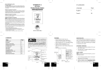
FEATURES
• Wireless Weather Station (Figure 1).
• Remote Temperature Sensor with optional
Channel 2 Probe (TX25U, Figure 2).
• Indoor Temperature (˚F or ˚C) and Indoor Humidity.
• Wireless Outdoor Temperature (˚F or ˚C).
• Optional Channel 2 Temperature Probe.
• Able to Receive up to 3 Remote Temperature
Sensors.
• Wall Hanging or Free Standing.
ADDITIONAL EQUIPMENT (not included)
1. Two fresh AA 1.5V alkaline batteries for the wire-
less weather station.
2. Two fresh AAA 1.5V alkaline batteries for the re-
mote temperature sensor.
3. One, Philips screwdriver for mounting.
QUICK SETUP
Hint:
Use good quality Alkaline Batteries; avoid re-
chargeable batteries.
1. Have the Wireless Weather Station and Tempera-
ture sensor 3 to 5 feet apart.
2. Batteries should be out of both units for 10 minutes.
3. Place the batteries into the Temperature sensor
first and next into the Wireless Weather Station.
4. DO NOT PRESS ANY BUTTONS FOR 15
MINUTES.
In this time the Wireless Weather Station and the tem-
perature sensor will begin to communicate with each
other, and the display will show both the indoor tem-
perature and an outdoor temperature. If the Wireless
12 or 24 Hour
Time Display
Connection w/
Sensor Icon
Low Battery
Indicator
Set / Channel
Button
Indoor Temperature
(˚F or ˚C)
Indoor Humidity
(%RH)
Channel Indicatop (1, 2
or 3)
Outdoor Temperature
(˚F or ˚C)
Minimum or Maximmum
Temperature &
Humidity
Minimum/Maximum/
+Button
Figure 1
Optional Probe
w/ 10 Foot Wire
Remote
Temperature
Sensor LCD
Temperature
Display
Wall-Mounting
Bracket
Figure 2
P.2
FCC ID: OMOTX25U (transmitter)
RF Exposure mobile:
The internal / external antennas used for this mobile transmitter must pro-
vide a separation distance of at least 20 cm (8 inches) from all persons and
must not be co-located or operating in conjunction with any other antenna
or transmitter.”
Statement according to FCC part 15.19:
This device complies with Part 15 of the FCC Rules. Operation is subject to
the following two conditions: (1) this device may not cause harmful
interference, and (2) this device must accept any interference received, in-
cluding interference that may cause undesired operation.
Statement according to FCC part 15.21:
Modifications not expressly approved by this company could void the user’s
authority to operate the equipment.
Statement according to FCC part 15.105:
NOTE:
This equipment has been tested and found to comply with the limits
for a Class B digital device, pursuant to Part 15 of the FCC Rules. These
limits are designed to provide reasonable protection against harmful inter-
ference in a residential installation. This equipment generates, uses and
can radiate radio frequency energy and, if not installed and used in accor-
dance with the instructions, may cause harmful interference to radio
communications.
However, there is no guarantee that interference will not occur in a particu-
lar installation. If this equipment does cause harmful interference to radio or
television reception, which can be determined by turning the equipment off
and on, the user is encouraged to try to correct the interference by one or
more of the following measures:
• Reorient or relocate the receiving antenna.
• Increase the separation between the equipment and receiver.
• Connect the equipment into an outlet on a circuit different from that to
which the receiver is connected.
• Consult the dealer or an experienced radio/TV technician for help

sor (see “A. Temperature sensor” below).
2. Within 2 minutes of powering up the sensor, insert
the batteries to the Weather Station (see “B. Wire-
less Weather station” below). Once the batteries
are in place, all segments of the LCD will light up
briefly. Following the indoor temperature and the
time as 12:00 will be displayed, and the signal re-
ception icon will flash. If they are not shown in LCD
after 60 seconds, remove the batteries and wait for
at least 60 seconds before reinserting them. Once
the indoor data is displayed user may proceed to
the next step.
3. After the batteries are inserted, the Weather Sta-
tion will start receiving data signal from the sensor.
The outdoor temperature should then be displayed
on the Weather Station. If this does not happen af-
ter 2 minutes, the batteries will need to be removed
from both units and reset from step 1.
A. TEMPERATURE SENSOR
1. Remove the Battery Cover.
2. Observing the correct polarity, install 2 “AAA” Alka-
line Batteries-make sure they do not spring free,
or start-up problems may occur.
3. Replace the Battery Cover.
B. WIRELESS WEATHER STATION
Note:
After the batteries are installed, DO NOT press
any buttons. This may interfere with the signals, caus-
ing temperatures to register incorrectly.
1. Remove the Battery Cover on the back of the Wire-
less Weather Station.
2. Observing the correct polarity, install 2 “AA” Alka-
line Batteries.
3. Replace Battery Cover.
4. Wait 15 minutes before pressing any buttons.
*
When the signal is successfully received by the
Weather Station, the icon will be switched on. (If
not successful, the icon will not be shown in LCD)
So the user can easily see whether the last recep-
tion was successful (icon on) or not (icon off). On
the other hand, the short blinking of the icon shows
that a reception is being done now.
FUNCTION KEYS
The simple design of this product features 2 keys.
SET/CH:
• Press and hold for 5 seconds to enter set-up mode.
• Press and release to toggle between channels.
MIN/MAX/+:
• Press and release to toggle between minimum,
maximum, and current temperature values.
• Press and hold 5 seconds to reset all minimum and
maximum recorded values.
• Press and release to advance hours and minutes.
• Press and release to toggle between 12 hour time
and 24 hour time.
OPERATIONS
12 OR 24 HOUR TIME SETTING
1. Press and hold the SET/CH button for 5 seconds.
2. “12h” will flash in the Time section of the LCD.
3. Press and release the MIN/MAX/+ button to toggle
between 12 hour time and 24 hour time.
4. Press and release the SET/CH button to confirm
selection and advance to the time setting.
Note:
Selecting 12 hour time will automatically select
Fahrenheit (˚F) temperature. Selecting 24 hour time
will automatically select Celsius (˚C) temperature.
TIME SETTING
1. Press and hold the SET button for 5 seconds.
2. “12h” or “24h” will appear flashing in the TIME sec-
tion of the LCD.
3. Press and release the SET/CH button once.
4. The hour will begin flashing.
5. Press and release the MIN/MAX/+ button to ad-
vance the hours.
6. Press and release the SET/CH button once more,
and the minutes will begin to flash.
7. Press and release the MIN/MAX/+ button to ad-
vance the minutes.
8. Press and release the SET/CH button to confirm
selection.
Note:
When in the 12-hour format “PM.” will appear
to the left of the hour in the time LCD between the hours
of noon and midnight.
OUTDOOR TEMPERATURE
The temperature received from the remote tempera-
ture sensor is viewed in the OUTDOOR LCD. When
there is more than one remote temperature sensor unit
in operation, a “boxed” number will appear to the right
of the temperature. This indicates which remote tem-
perature sensor unit (1, 2, or 3) is currently displaying
its data in the OUTDOOR LCD. (This feature is ex-
plained in further detail in the section-Adding Remote
Temperature Sensors).
VIEWING MINIMUM AND MAXIMUM TEMPERATURE
RECORDS
The WS-9029U keeps a record of the MINIMUM and
MAXIMUM indoor and outdoor temperatures.
To view minimum and maximum temperatures: press
the MIN/MAX/+ button once. “MIN” appears in the bot-
tom left of the LCD. The indoor and outdoor tempera-
tures displayed when “MIN” appears are the minimum
recorded values. The minimum records will display for
30 seconds before returning to the normal display mode.
Press the min/max/+ button again (once while “MIN” is
still displayed, twice otherwise). “MAX” appears in the
bottom right of the LCD. The indoor and outdoor tem-
peratures displayed when “MAX” appears are the maxi-
mum recorded values. The maximum records will dis-
play for 30 seconds before returning to the normal dis-
play mode.
While “MAX” is still displayed press the MIN/MAX/+
button again to return to the current data display. Or
you can wait 30 seconds, during either the minimum or
the maximum readings, and the unit will automatically
return to current data readings.
GB
P.6
GB
P.7
GB
P.8
GB
P.9
GB
P.10
GB
P.11
GB
P.12
GB
P.13
Battery Cover
Remote Temperature Sensor
(TX-25U)
Battery
Compartment
Battery Compartment
Battery Cover
Wireless Weather Station
Sensor Signal
reception icon
*
Weather Station does not display both temperatures
after the 15 minutes, please retry the set up as stated
above. After both indoor and outdoor temperatures
are displayed for 15 minutes you can place your tem-
perature sensor outdoors, and set your time.
The temperature sensor should be placed in a dry,
shaded area (ex: under the eve of a roof). The tem-
perature sensor has a range of 330 feet. Any walls
that the signal will have to pass through will reduce
distance. An outdoor wall or window will have up to 20
feet of resistance and an interior wall will have up to 10
feet of resistance. Your distance plus resistance should
not exceed 330 feet in a straight line.
NOTE:
Fog and mist will not harm your temperature
sensor, but direct rain must be avoided.
DETAILED SETUP GUIDE
I. BATTERY INSTALLATION (When one Tempera-
ture sensor is being used)
1. First, insert the batteries to the Temperature sen-

The Weather Station will automatically detect the tem-
perature probe and will display the temperature probe
data in channel 2.
ADDING TEMPERATURE SENSORS (OPTIONAL)
The WS-9029U is able to receive signals from 2 re-
mote temperature sensors (TX-25U). These extra sen-
sors can be purchased through the same dealer as
this unit
A. SET-UP OF MULTIPLE SENSORS
1. Remove all the batteries from the receiver and
sensor(s) and wait 60 seconds. During these 60
seconds, press any button 20 times to discharge
any excess power.
2. Insert the batteries to the first sensor.
3. Within 2 minutes of powering up the first sensor
(Temperature sensor with probe), insert the batter-
ies to the Weather Station. Once the batteries are
in place, all segments of the LCD will light up briefly.
Following the indoor temperature/humidity and the
time as 12:00 will be displayed, and the signal re-
ception icon will flash. If they are not shown in LCD
after 60 seconds, remove the batteries and wait for
at least 60 seconds before reinserting them.
4. The outdoor temperature from the first sensor
(channel 1) should then be displayed on the
Weather station. If this does not happen after 2
minutes, the batteries will need to be removed from
both units and reset from step 1.
5. If the temperature probe has been used, the out-
door temperature from channel 2 will then be
displayed. Otherwise, the outdoor temperature will
display “—”.
Note:
The temperature probe from the first sen-
sor will always occupy “channel 2”. Channel 2 can
only be used for the temperature probe. If you
choose not to use the temperature probe, Channel
2 will display “—”.
6. Insert the batteries to the second sensor as soon
as the outdoor temperature readings from the first
sensor are displayed on the Weather station.
NOTE:
You must insert the batteries into the
second sensor within 30 seconds of reception
of the first sensor.
7. The outdoor temperature from the second sensor
and the “channel 3” icon should then be displayed
on the Weather station. If this does not happen af-
ter 2 minute, the batteries will need to be removed
from all the units and reset from step 1.
Note:
only the readings from the internal sensor
of the second sensor will be displayed in “channel
3”
IMPORTANT:
Transmission problems will arise if the
setting for additional sensors is not followed as de-
scribed above. Should transmission problems
occur, it is necessary to remove the batteries from
all units and start again the set-up from step 1.
B. VIEWING AND OPERATING WITH MULTIPLE
TEMPERATURE SENSOR UNITS
1. To view the temperature of a different remote tem-
perature sensor unit, press and release the SET/
CH button. A shift from one “boxed” number to the
next should be observed in the OUTDOOR LCD.
2. To determine which remote temperature sensor
reading is displayed on the 3 channels, match the
temperature displayed on each channel, with the
corresponding temperature displayed on the LCD
of each remote temperature sensor.
3. To view the Minimum/Maximum temperature: first
select which remote temperature sensor to read
data from (indicated by the “boxed” number), then
press the SET/CH button. Pressing this button once
will display the minimum temperature, and the date
and time the data was recorded. Pressing this but-
ton a second time (while “MIN” is still displayed,
otherwise press the button twice) will display the
same data for the maximum recordings.
4. To reset the Minimum/Maximum readings, press
and hold the MIN/MAX/+ button for 5 seconds, this
will reset all the minimum and maximum data from
all sensors.
MOUNTING
THE REMOTE TEMPERATURE SENSOR
1. Remove the mounting bracket/stand from the tem-
perature sensor.
2. Place the mounting bracket over the desired
location.
3. The mounting bracket can attach to the sensor in
the middle of the back or on the bottom.
4. Through the 3 screw holes of the bracket, mark the
mounting surface with a pencil.
5. Screw mounting bracket onto the mounting surface.
Ensure that the screws are flush with the bracket.
6. Insert the remote temperature sensor into the
bracket.
THE WIRELESS WEATHER STATION
The wireless weather station can be mounted in 2 ways:
• with the table stand or,
• on the wall with the use of a wall hanging screw
(not included).
A. USING THE TABLE STAND
The wireless weather station comes with the table stand
attached. If you wish to use the table-stand all that is
required is to pull out the table stand on the back of the
receiver and place the receiver on a flat surface.
B. WALL MOUNTING
1. Make sure the table stand is flush against the wire-
less weather station.
2. Fix a screw (not included) into the desired wall, leav-
ing approximately 1/4 of an inch (5mm) extended
from the wall.
3. Place the wireless weather station onto the screw
using the hanging hole on the backside.
4. Gently pull the wireless weather station down to
lock the screw into place.
TROUBLESHOOTING
NOTE:
For problems not solved, please contact La
Crosse Technology.
Problem: Hour is incorrect (minute and date are correct)
Solution:
Be sure correct time zone and daylight saving time
settings are selected.
Problem: The LCD is faint
Solution:
1. Set the LCD contrast to a higher number
GB
P.14
GB
P.15
GB P.16 GBP.17
GB
P.18
GB
P.19
GB
P.20
GB
P.21
Back middle of sensor
inserted into Mounting
Bracket
Bottom of sensor
inserted into
Mounting Bracket
RESETTING THE MIMIMUM AND MAXIMUM
RECORDS
All the minimum and maximum records (minimum and
maximum) will be reset after the MIN/MAX/+ button is
pressed and held for 5 seconds.
OPTIONAL CHANNEL 2 TEMPERATURE PROBE
When the temperature probe is connected to the re-
mote temperature sensor, the WS-9029U’s channel 1
will display the remote temperature sensor data, and
channel 2 will display the temperature probe data. The
remote temperature sensor data will always be dis-
played on the channel 1 and the temperature probe on
the channel 2.
If the probe on remote temperature sensor is
unplugged, the “probe channel” on WS-9029U LCD will
show “—”, the remote temperature sensor displayed
value will still be shown.
The probe can be connected to the remote tempera-
ture sensor anytime. There is no need to reset the units.

for different working environments. The indoor sensor
is less responsive to ambient air currents because of
the shielding effect of the display’s case. In addition,
the case can act as a heat sink to absorb and store
heat from external sources (i.e. handling of the case or
radiant heat). Also, the much greater range of the re-
mote temperature sensor requires a different calibra-
tion curve than the indoor range. Error is usually greater
at the extreme ends of a range, making it harder to
compare different ranges with different curves. Under
non-laboratory conditions, it is difficult to compensate
for the above factors and obtain an accurate
comparison.
MAINTENANCE AND CARE INSTRUCTIONS
• Extreme temperatures, vibration, and shock should
be avoided to prevent damage to the units.
• Clean displays and units with a soft, damp cloth.
Do not use solvents or scouring agents; they may
mark the displays and casings.
• Do not submerge in water.
• Immediately remove all low powered batteries to
avoid leakage and damage.
• Opening the casings invalidates the warranty. Do
not try to repair the unit. Contact La Crosse Tech-
nology for repairs.
SPECIFICATIONS
Temperature measuring range:
Indoor: 14.1˚F to 139.8˚F with 0.2˚F resolution.
“OFL” displayed if outside this range.
Outdoor: -39.8˚F to 139.8˚F with 0.2˚F resolution.
“OFL” displayed if outside this range.
Indoor relative humidity
measuring range: 1% to 99% with 1% resolution.
(“- -” displayed if outside this range.
Indoor Temperature
checking interval: Every 15 seconds.
Outdoor Temperature checking interval
(Remote Control Sender): Every 4 seconds.
Transmission Range: 330 feet (in open space).
Power Supply:
Weather Station: 2 x AA, IEC LR6, 1.5V.
Temperature Transmitter: 2 x AAA, IEC LR3, 1.5V.
Battery life cycle: Approximately 24 months.
Recommended battery type: Alkaline.
Dimensions (L x W x H)
Weather Station: 2.91" x 1.15" x 3.86"
(74 x 29.1 x 98mm).
Temperature Sensor: 1.44" x 0.76" x 4.80"
(36.6 x 19.3 x 121.8 mm)
WARRANTY INFORMATION
La Crosse Technology, Ltd provides a 1-year limited
warranty on this product against manufacturing defects
in materials and workmanship.
This limited warranty begins on the original date of
purchase, is valid only on products purchased and used
in North America and only to the original purchaser of
this product. To receive warranty service, the purchaser
must contact La Crosse Technology, Ltd for problem
determination and service procedures. Warranty ser-
vice can only be performed by a La Crosse Technology,
Ltd authorized service center. The original dated bill
of sale must be presented upon request as proof of
purchase to La Crosse Technology, Ltd or La Crosse
Technology, Ltd’s authorized service center.
La Crosse Technology, Ltd will repair or replace this
product, at our option and at no charge as stipulated
herein, with new or reconditioned parts or products if
found to be defective during the limited warranty pe-
riod specified above. All replaced parts and products
become the property of La Crosse Technology, Ltd and
must be returned to La Crosse Technology, Ltd. Re-
placement parts and products assume the remaining
original warranty, or ninety (90) days, whichever is
longer. La Crosse Technology, Ltd will pay all expenses
for labor and materials for all repairs covered by this
warranty. If necessary repairs are not covered by this
warranty, or if a product is examined which is not in
need or repair, you will be charged for the repairs or
examination. The owner must pay any shipping charges
incurred in getting your La Crosse Technology, Ltd prod-
uct to a La Crosse Technology, Ltd authorized service
center. La Crosse Technology, Ltd will pay ground re-
turn shipping charges to the owner of the product to a
USA address only.
Your La Crosse Technology, Ltd warranty covers all
defects in material and workmanship with the following
specified exceptions: (1) damage caused by accident,
unreasonable use or neglect (including the lack of rea-
sonable and necessary maintenance); (2) damage
occurring during shipment (claims must be presented
to the carrier); (3) damage to, or deterioration of, any
accessory or decorative surface; (4) damage resulting
from failure to follow instructions contained in your
owner’s manual; (5) damage resulting from the perfor-
mance of repairs or alterations by someone other than
an authorized La Crosse Technology, Ltd authorized
service center; (6) units used for other than home use
(7) applications and uses that this product was not in-
tended or (8) the products inability to receive a signal
due to any source of interference.. This warranty cov-
ers only actual defects within the product itself, and
does not cover the cost of installation or removal from
a fixed installation, normal set-up or adjustments, claims
based on misrepresentation by the seller or perfor-
mance variations resulting from installation-related
circumstances.
LA CROSSE TECHNOLOGY, LTD WILL NOT AS-
SUME LIABILITY FOR INCIDENTAL,
CONSEQUENTIAL, PUNITIVE, OR OTHER SIMILAR
DAMAGES ASSOCIATED WITH THE OPERATION OR
MALFUNCTION OF THIS PRODUCT. THIS PROD-
UCT IS NOT TO BE USED FOR MEDICAL PUR-
POSES OR FOR PUBLIC INFORMATION. THIS
PRODUCT IS NOT A TOY. KEEP OUT OF
CHILDREN’S REACH.
This warranty gives you specific legal rights. You may
also have other rights specific to your State. Some
States do no allow the exclusion of consequential or
incidental damages therefore the above exclusion of
limitation may not apply to you.
For warranty work, technical support, or information
contact:
La Crosse Technology
2809 Losey Blvd. South
La Crosse, WI 54601
Phone: 608.782.1610
Fax: 608.796.1020
e-mail:
support@lacrossetechnology.com
(warranty work)
(information on other products)
web:
www.lacrossetechnology.com
Questions? Instructions? Please visit:
www.lacrossetechnology.com/9029
All rights reserved. This handbook must not be repro-
duced in any form, even in excerpts, or duplicated or
processed using electronic, mechanical or chemical
procedures without written permission of the publisher.
This handbook may contain mistakes and printing
errors. The information in this handbook is regularly
checked and corrections made in the next issue. We
accept no liability for technical mistakes or printing
errors, or their consequences.
All trademarks and patents are acknowledged.
GB
P.22
GB
P.23
GB
P.24
GB
P.25
GB
P.26
GB
P.27
GB
P.28
GB
P.29
2. Replace batteries
Problem: No outdoor temperature is displayed.
Solution:
1. Remove all batteries, reinsert into sensor first, then
into the wireless weather station.
2. Place remote temperature sensor closer to wire-
less weather station.
3. Be sure all batteries are fresh.
4. Place remoter temperature sensor and wireless
weather station in position so the straight-line sig-
nal is not passing through more than 2 or 3 walls.
Problem:
Temperatures do not match if units are placed next to
each other.
Solution:
Each remote temperature sensor is manufactured to
be accurate to within 1 degree plus or minus and un-
der normal conditions, so two sensors could be as much
as 2 degrees different. However, the difference can be
exaggerated further because the sensors are designed
/