GRAB
HERE
TO
OPEN
TECHNICIAN’S REFERENCE
GUIDE
IMPORTANT!
Keep this guide with this unit.
Fold and return to the plastic
envelope for storage.
DA2243i
003-1927-00 Rev. B
TRACK LIGHT with MONITOR
MODEL 153830-00X
DIAGNOSTIC GUIDE
Condition Check Solution
No HDMI video and /
or audio present on
the monitor
1.
Monitor is not on HDMI
input.
Set monitor to HDMI input.
2.
HDMI cable has no
“Repeater”.
Install the recommended HDMI Repeater and
Voltage Inserter.
3.
Cable connections are
loose or not properly
connected.
Repair connections.
4.
Power needs to be cycled
on the “Repeater”.
Cycle power on the “Repeater” by unplugging
the “Voltage Inserter” power cord from the
outlet and plugging it back in.
Monitor drifts when
released from desired
position.
1.
Monitor pivot joint tension
requires adjustment.
Adjust pivot joint tension on monitor mount
(complete instructions in User’s Guide).
Light will not operate
when any function is
selected.
1.
Light is in Auto On mode
and flex arm is positioned
above horizontal plane.
Lower flex arm so that it is below the
horizontal plane. Light will come on.
2.
Bulb is burned out or bad
socket.
Replace bulb or socket.
3.
Power to light is Off. Turn on power at source.
4.
Fuse is open or blown. Replace F1 fuse (refer to wiring diagram.)
5.
Transformer open or
malfunctioning.
Check continuity. If open winding(s) replace
transformer.
6.
Wire broken within light
arm, flex arm or pivot joint.
Replace light harness(es).
7.
Light control PCB
malfunctioning.
Replace PCB with known good one.
Lighthead illuminates
but not a correct
intensity.
1.
Faulty bulb Replace bulb.
2.
Facility Power is low. Power should be 115 VAC (+/- 10%).
3.
Lighthead shield is clouded
(may be due to using too
strong disinfect / cleaning
solution.
Replace Shield assembly.
Light is out of focus,
not producing a sharp
pattern.
1.
Light is out of focus. Adjust light for desired focus. Focus is set
at factory at 27" (69 cm). See instructions on
opposite side or in User’s Guide.
DIAGNOSTIC GUIDE
Condition Check Solution
Monitor will not
power On.
Monitor LED:
Green: Power ON.
Amber: Power is On
(Standby) No signal.
Black: Power OFF.
1.
Check supply line voltage to TB1
terminal board.
If no voltage is present check supply
line fuse or circuit breaker in facility.
2.
Check batteries (two 1.5 VAC, AAA
batteries) in Remote Control.
If weak or dead replace batteries.
3.
Press Power switch on Monitor.
Monitor LED should be green.
Press Monitor Power switch.
If Monitor is powered but no signal is
present the LED will be Amber.
4.
Check all connections and
harnesses from supply line voltage
to Power Supply board and 12
VDC from Power Supply board to
Monitor.
Correct or replace connections or
harnesses.
5.
Check for 12 VDC output on Power
Supply board between +V and
Gnd. terminals.
If no voltage present replace Power
Supply board.
6.
Substitute a known good 12 VDC
Monitor and check operation.
If the substituted Monitor functions,
replace Monitor.
Track Monitor screen
is black.
1.
If Monitor LED is Amber colored
there is no signal to the monitor.
There is no signal coming from the
video source.
2.
Check all cables and the
connections in track and flex arms
to assure they are good.
Correct connections or replace
damaged cables.
Monitor picture is
“fuzzy” or “blurry”
when on Cable or PC
mode.
1.
Check ground wire connected to
the Line Power terminal board
(TB1).
Assure ground connection is secure.
2.
If HDMI is being used, a repeater
is required.
Install a repeater in the HDMI Line.
3.
Adjust Monitor settings. Refer to Corrections for Monitor
Distortion on this reference.
4.
Check all harnesses and
connections.
Correct connections and / or replace
problem harnesses.
5.
Assure good cable TV signal is
being supplied to system using a
known good Monitor or TV.
Contact cable supplier to correct
signal problems related to supplier.
6.
Too many connections on cable(s)
between video source and monitor.
Only 1 (One) cable per input between
source and monitor is recommended.
7.
Cable is below minimum
recommended specification for
optimal output.
Assure cable specifications meet
or excede the recommended cable
specifications.
No Audio
1.
Check the Volume control on the
PC, and the Monitor.
Turn up volume on the PC and the
monitor.
2.
Check all connections and cables
on the Audio.
Assure all connections are secure
and the cables are good. The 3.5mm
audio must be connected to a PC
Sound Card or an Audio Source.
Monitor has no
picture, picture is
not clear, or various
colored lines appear.
1.
Solid Red, Blue, Green, or Yellow
colors appear with picture.
Broken wires in the VGA
harnesses produce these results:
Red wire = No red color on
Monitor.
Blue wire = No blue color on
Monitor.
Green wire = No green color on
Monitor.
Repair or replace the faulty
harness(es).
2.
Solid White Screen.
Check connections.
Repair connections.
No picture when on
Satellite or Digital
Tuner.
1.
Check connections and channels
on tuner.
Use the satellite remote to change
satellite channels.
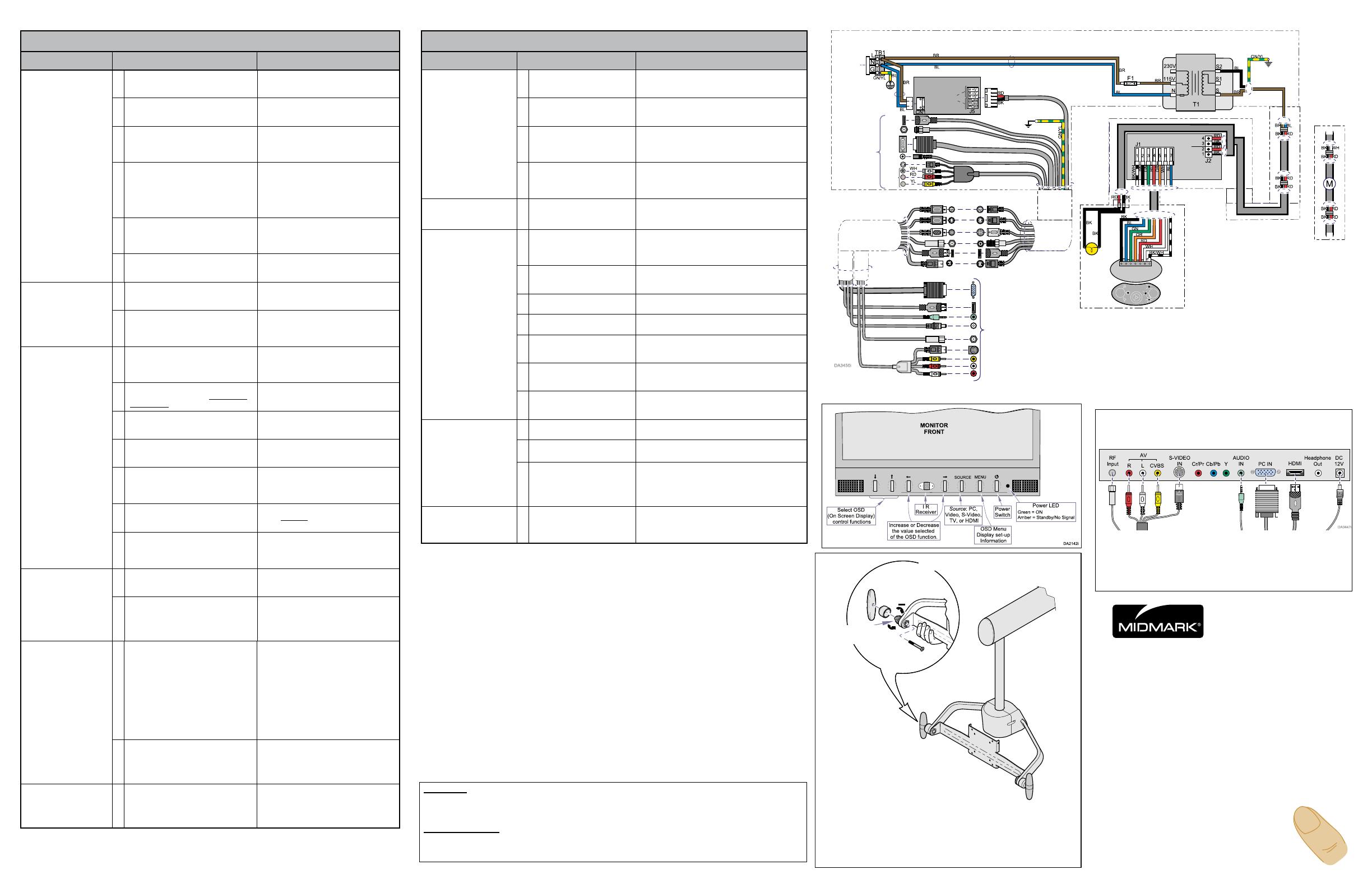
• Removehandle&cover.
• Whileholdingmount,turn
adjusting screw to increase
(+) or decrease (-) the tension.
Monitor Tension Adjustment
Adjustment
Nut
NOTE
For Tension Adjustments at the Arm, Yoke, and Lighthead
pivots refer to the User’s Guide (003-1926-00).
Connections (Monitor)
(Basic Connections Shown)
For a clean appearance, attach all connectors to the moni-
tor even though some may not be attached to the source.
For additional setups refer to the Quick
Installation Guide (003-1928-00).
Repeater
An electronic device that receives and retransmits a signal at a higher power, or onto the other
side of an obstruction, so the signal can cover longer distances.
Voltage Inserter
A power supply that is used to by-pass the output power from an electronic device (DVD Player)
because the load may require more power than the device can supply.
Monitor Flex Arm
Connect to
Monitor
Suspension
Tube
User
Connections
Foot End of Track
Head End of Track
120 VAC
1.5 Amp
50/60 Hz
Connects
to Facility
PC, DVD,
TV, etc.
12 VDC
Monitor
Power
Transformer
Light Flex Arm
Additional
Suspension
Tube
Light
Head
Bulb

