Page is loading ...

Setup Guide — DVI DL 201 Tx/Rx
W
These instructions provide a quick setup guide for experienced installers. Installation
and service must be performed by authorized personnel only.
N
The DVI DL 201 Tx/Rx works with unshielded twisted pair (UTP) cable or shielded twisted
pair (STP) cable. STP cables are required to ensure FCC Class A and CE compliance.
C
Always use a power
supply specified by
Extron for this unit.
Use of an unauthorized
power supply voids all
regulatory compliance
certification and
may cause damage
to the supply and the
transmitter or receiver.
N
One power supply is provided
when the transmitter and
receiver are purchased
together. A power supply is
not provided when either unit
is purchased separately.
Step 1
Turn off all equipment or disconnect
it from power sources. Mount the
transmitter and receiver as desired.
Follow the instructions included with the
appropriate mounting kit.
Step 2
Use the three port captive screw
connections to transmit pass-through
RS-232 and IR signals from a control
device to a remote device. RS-232 signals
are bidirectional and use three wires
(see diagram A. at right). IR signals are
unidirectional and use two wires (see
diagram B. at right). In each case the
control device is wired to the transmitter in
exactly the same way as the remote device
is wired to the the receiver.
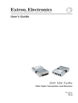
The Extron
®
DVI DL 201 Tx and DVI DL 201 Rx are dual
link DVI transmitter (Tx) or receiver (Rx) units. Using
three CAT 5/5e/6/7 twisted pair cables, DVI-D signals
can be extended up to 100 feet (30 m) at resolutions up to
2560x1600 @ 60 Hz. They can be purchased as a pair or as
individual units.
DVI DL 201 Rx
DVI-D OUTPUT
Tx Rx
CONTROL
PASS THRU
12V
0.4A MAX
POWER
DVI-D INPUT
RS-232
PASS-THRU
DO NOT
CONNECT
OUTPUTS
TO LAN
DDC ROUTE
REMOTE
SPARE
LOCAL
LOCAL OUTPUT OUTPUT
1
2
3
Extron
DVI DL 201 Tx
Dual Link DVI
Transmitter
PC w/ Dual Link DVI
Output
Local
Monitor
Control
System
Dual Link
DVI Cable
RS-232
RS-232
Extron
DVI DL 201 Rx
Dual Link DVI
Receiver
2560 x 1600 Flat Panel
Display with Dual-Link
DVI Input
CAT 5/5e/6/7 Cables
up to 200 feet
Tx Rx
CONTROL
P
ASS THRU
S G
DVI DL 201
Transmitter
or Receiver
IR Control
or IR emitter
B.
Tx Rx
CONTROL
PASS THRU
Tx Rx
DVI DL 201
Transmitter
or Receiver
RS-232 Control
or Display Device
A.
Step 3
Determine how the source device will obtain the EDID information and perform
one of the following procedures:
Option 1 — To capture the EDID of a desired display and store it in the EDID
Minder for future use:
a. Connect the display to the local monitor output of the transmitter.
b. Power on the transmitter and the local monitor.
c. Configure the DDC switches as shown in the figure at right.
ON
1 2 3
ON
OFF
DEFAULT EDID
EDID MINDER
REMOTE DDC

Setup Guide — DVI DL 201 Tx/Rx (cont’d)
Extron USA - West
Headquarters
+800.633.9 876
Inside USA / Canada Only
+1.714.4 91.1500
+1.714.4 91.1517 FAX
Extron USA - East
+800.633.9 876
Inside USA / Canada Only
+1.919.863.1794
+1.919.863.1797 FAX
Extron Europe
+800.3987.6673
Inside Europe Only
+31.33.453.4040
+31.33.453.4050 FAX
Extron Asia
+800.7339.8766
Inside Asia Only
+65.6383.4400
+65.6383.4664 FAX
Extron Japan
+81.3.3511.765 5
+81.3.3511.765 6 FAX
Extron China
+400.883.1568
Inside China Only
+86.21.3760.1568
+86.21.3760.1566 FAX
Extron Middle East
+971.4.299180 0
+971.4.299188 0 FAX
© 2010 Extron Electronics. All rights reserved.
d. Press and release the EDID “Store” button (see the figure at right). The
rear panel LED turns amber while the EDID information is read and
stored from the local monitor. Afterwards, the LED turns green.
e. Power off and disconnect the display from the transmitter.
f. Connect the transmitter to the receiver.
g. Connect a source device to the transmitter.
h. Connect a display device to the receiver and, if required, a local monitor to the transmitter.
i. Power on the display device(s), the transmitter, and the receiver.
j. Power on the source device.
Option 2 — To use the default EDID (2560x1600 @ 60 Hz):
a. Configure the DDC switches as shown in the figure at right.
b. Connect a source device to the transmitter.
c. Connect a display device to the receiver and, if required, a local monitor to
the transmitter.
d. Connect the transmitter and receiver.
e. Power on the transmitter, receiver, and display devices.
f. Power on the source device.
Option 3 — To use DDC pass-through routed to the local monitor:
a. Configure the DDC switches as shown in the figure at right.
b. Connect a source device to the transmitter.
c. Connect a display device to the receiver and, if required, a local monitor to
the transmitter.
d. Connect the transmitter and receiver.
e. Power on the transmitter, receiver, and local monitor.
f. Power on the source device.
g. Power on the display device.
Option 4 — To use DDC pass-through routed to the remote display:
a. Configure the DDC switches as shown in the figure at right.
b. Connect a source device to the transmitter.
c. Connect a display device to the receiver and, if required, a local monitor to
the transmitter.
d. Connect the transmitter and receiver.
e. Power on the transmitter, receiver, and display devices.
f. Power on the source device.
Troubleshooting
For complete instructions, consult the User’s Manual, which is available at the Extron website.
If problems are encountered, verify that the cables are routed and connected properly.
If the problems persist, contact the Extron Service Department.
ON
1 2 3
ON
OFF
DEFAULT EDID
EDID MINDER
REMOTE DDC
ON
1 2 3
ON
OFF
DEFAULT EDID
EDID MINDER
REMOTE DDC
ON
1 2 3
ON
OFF
DEFAULT EDID
EDID MINDER
REMOTE DDC
STORE
EDID
68-1531-50
Rev. A
01 10
/