
27" (69 cm) Wide
LAUNDRY CENTER
Washer- Electric Dryer
CENTRO DE LAVANDERiA
de 27" (69 cm) de ancho
Lavadora - Secadora electrica
iii
\
P/N 134809300 (0610) Sears, Roebuck and Co., Hoffman Estates, IL 60179 U.S.A. www.sears.com

Contents
SUBJECT PA GE
Pre-lnstallation Requirements .......................................... 2
Electrical Requirements ................................................... 2
Water Supply Requirements ........................................... 2
Drain Requirements .......................................................... 3
Exhaust System Requirements .................................. 3-4
Gas Supply Requirements ................................................ 4
Location ............................................................................ 4
Rough-In Dimensions ....................................................... 4
Mobile Home Installation ................................................. 5
Unpacking ......................................................................... 5
Electrical Installation ........................................................ 6
Grounding Requirements ................................................ 6
3 & 4-Wire Connections ........................................... 6-7
Installation .................................................................... 7-8
Replacement Parts........................................................... 8
Before beginning installation, carefully read these instructions.
This will simplify the installation
and ensure the laundry center is installed correctly and safely.
Leave these instructions near the
laundry center after installation for future reference.
NOTE: The electrical service to the laundry center must con-
form with local codes and ordinances and the latest edition of
the National Electrical Code, ANSI/NFPA 70, or in Canada, the
Canadian Electrical Code, CSA C22.1
NOTE: The gas service to the laundry center must conform with
local codes and ordinances and the latest edition of the National
Fuel Gas Code ANSIZ223. I/NFPA 54, or in Canada, the Canadian
Natural Gas andPropane Installation Code, CSA B149. 1.
NOTE: The laundry center is designed under ANSI Z21.5.1 or
ANSI/UL 2158- CAN/CSA C22.2 No. 112 (latest edition) for HOME
USE only. This laundry center is not recommended for commer-
cial applications such as restaurants or beauty salons, etc.
For your safety the information in this manual must
be followed to minimize the risk of fire or explosion or to prevent
property damage, personal injury or loss of life.
- Do not store or use gasoline or other flammable vapors and
liquid in the vicinity of this or any
other appliance.
- WHAT TO DO IF YOU SMELL GAS
Do not try to light any appliance.
Do not touch any electrical switch; do not use any phone in
your building.
Clear the room, building or area of all occupants.
Immediately call your gas supplier from a neighbor's phone.
Follow the gas supplier's instructions.
If you cannot reach your gas supplier, call the fire
department.
Installation and service must be preformed by a qualified installer,
service agency or the gas supplier.
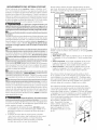
ELECTRICAL REQUIREMENTS
ELECYRICLaundry Center
Circuit- Individual 30 amp branch circuit fused with 30 amp minimum
time delay fuses or circuit breakers.
POWER SUPPLY - 3-wire or 4-wire, 240 volt, single phase, 60 Hz,
Alternating Current.
POWER SUPPLY CORD KIT- The laundry center MUST employ a 3-
condutor power supply cord NEMA 10-30 type SRDT rated at 240
volt AC minimum, 30 amp, with 3 open end spade lug connectors
with upturned ends or closed loop connector OR a 4-condutor power
supply cord NEMA 14-30 type SRDT or ST (as required) rated at 240
volt AC minimum, 30 amp, with 4 open end spade lug connectors
with upturned ends or closed loop connectors and marked for use
with clothes dryers. If being installed in a new branch circuit
installation, manufactured (mobile) home, recreational vehicle or area
which prohibits grounding through the neutral conductor, the laundry
center MUST employ a 4-condutor power supply cord NEMA 14- 30
type SRDT or ST (as required) rated at 240 volt AC minimum, 30 amp,
with 4 open end spade lug connectors with upturned ends or closed
loop connectors and marked for use with clothes dryers. See
ELECTRICAL CONNECTIONS. (Canada - 4-wire power supply cord is
installed on laundry center.)
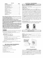
OUTLET RECEPTACLE- NEMA 10-30R (3-wire) receptacle or NEMA
14- 30R (4-wire) receptacle to be located so the power supply cord is
accessible when the laundry center is in an installed position.
NEMA 10-30R NEMA 14-30R
GAS Laundry Center
CIRCUIT - Individual 15 amp minimum branch circuit fused with a
time delay fuse or circuit breaker.
POWER SUPPLY -3 wire, 120 volt single phase, 60 Hz, Alternating
Current.
POWER SUPPLY CORD -The gas laundry center is equipped with a
120 volt 3-wire power cord.
NOTE: Do not under
any circumstances
remove grounding
prong from plug.
PRE-INSTALLATION REQUIREMENTS
Tools and Materials Required for Installation:
1. Phillips head screwdriver.
2. Channel-lock adjustable pliers.
3. Carpenter's level.
4. Flat or straight blade screwdriven
5. Duct tape.
6. Rigid or flexible metal 4 inch (10.16 cm) duct.
7. Vent hood.
8. Pipe thread sealer (Gas).
9. Ratchet with 3/8 inch (0.96 cm) socket.
Grounding Prong
WATER SUPPLY REQUIREMENTS
Hot and cold water faucets MUST be installed within 42 inches
(106.68 cm) of your laundry center's water inlet. The faucets MUST
be 3/4 inch (1.9 cm) garden hose type so inlet hoses can be connected.
Water pressure MUST be between 10 and 120 pounds per square
inch (maximum unbalance pressure, hot vs. cold, 10 psi). Your water
department can advise you of your water pressure. The hot water
temperature should be about 120 degrees E

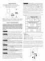
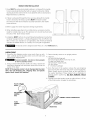
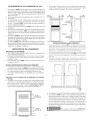
DRAIN REQUIREMENTS
1. Drain capable of eliminating 17 gals. per minute.
2. A standpipe diameter of 1¼ inches (3.18 cm) minimum.
3. The standpipe height above the floor should be:
Minimum height: 33 inches (83.82 cm)
Maximum height: 96 inches (244 cm)
--T--
33" Min.
(83.82cm)
f
96"Max.
(244 cm)
NOTE: For installations requiring a longer drain hose, have a qualified
technician install a longer hose, PIN 134049201, available from an
authorized parts distributor. For drain systems in the floor, install a
siphon break kit, available from your local hardware store.
EXHAUST SYSTEM REQUIREMENTS
Use only 4 inch (10.16 cm) diameter (minimum) rigid or flexible
metal duct and approved vent hood which has a swing-out
damper(s) that opens when the dryer is in operation. When the
dryer stops, the damper(s) automatically closes to prevent drafts
and the entrance of insects and rodents. To avoid restricting the
outlet, maintain a minimum of 12 inches (38,5 cm) clearance
between the vent hood and the ground or any other
obstruction.
The following are specific requirements for proper
and safe operation of your laundry center. Failure to follow these
instructions can create excessive drying times and fire hazards.
Do not use plastic flexible duct or metal foil to
exhaust the dryer. Excessive lint can build up inside the exhaust
system and create a fire hazard and restrict air flow. Restricted air
flow will increase drying times. If your present system is made up of
plastic duct or metal foil duct, _lace it with a rigid or flexible metal
duct. Ensure the present duct is free of any lint prior to installing
laundry center dryer duct.
If the dryer is not exhausted outdoors some fine
lint will be expelled into the laundry area. An accumulation of lint in
any area of the home can create a health and fire hazard. The dryer
exhaust system MUST be exhausted to the outside of the
dwelling!
Do not allow combustible materials (for example:
clothing,draperies/curtains, paper) to come in contact with the
exhaust system. The dryer MUST NOT be exhausted into a chimney,
a wall, a ceiling, or any concealed space of a building which can
accumulate lint, resulting in a fire hazard.
Do not exceed the length of duct pipe or number of
elbows allowed in the" EXHAUST DUCT LENGTHS" chart. Lint can
accumulate in the system, plugging the system and creating a fire
hazard, as well as increasing drying times.
_Do not the exhaust ends of the vent
screen
system,
nor use any screws or rivets to assemble the exhaust system. Lint can
become caught in the screen, on the screws or rivets, clogging the
exhaust system and creating a fire hazard as well as increasing drying
times. Use an approved vent hood to terminate the duct outdoors,
and seal all joints with duct tape. All male duct pipe fittings MUST
be installed downstream with the flow of air. 3
Explosion hazard, Do not install the laundry center
where gasoline or other flammables are kept or stored.If the laundry
center is installed in a garage, it must be a minimum of 18 inches
(45.7 cm) above the floor. Failureto do socan result in death, explosion,
fire or burns. The exhaust system back pressure MUST not exceed
0.6 inches (1.52 cm) of water column, measured with an inclined
manometer at the point the exhaust connects to the dryer. The
exhaust system should be inspected and cleaned a minimum of
every two years with normal usage. The more the dryer is used, the
more often you should check the exhaust system and vent hood for
proper operation.
The maximum length of the exhaust system depends upon the type
of duct used, number of elbows and type of exhaust hood.
The maximum length for both rigid and flexible duct is shown in the
chart below.
Number
of 90°
Turns
0
1
2
3
0
1
2
3
EXHAUST DUCT LENGTHS
EXHAUST HOOD TYPE
(10.2 CM) Louvered (635 CM)
MAXIMUM LENGTH OF 4-INCH (10.2 CM)
DIAMETER RIGID METAL DUCT
56 ft. (17.07 m) 42 ft. (12.8 m)
46 ft. (14.02 m) 36 ft. (10.97 m)
34 ft. (10.36 m) 28 ft. (8.53 m)
32 ft. (9.75 rn) 18 ft. (5.48 m)
MAXIMUM LENGTH OF 4-INCH (10.2 CM)
DIAMETER FLEXIBLE METAL DUCT
30 ft. (9.14 m)
22 ft. (6.7 rn)
16 ft. (4.88 m)
10 ft. (3.05 m)
22 ft. (6.7 m)
14 ft. (4.27 rn)
10 ft. (3.05 m)
5 ft. (1.5 m)
The laundry center may be exhausted four (4) ways with rear flush
installation:
1. Straight back
2. Down (8 inch [20.32 cm] length of 4 inch [10.16 cm] rigid duct
and 1 elbow down)
3. Left (8 inch [20.32 cm] length of 4 inch [10.16 cm] rigid duct, 1
elbowdown and 1 elbow left)
4. Right (8 inch [20.32 cm] length of 4 inch [10.16 cm] rigid duct, 1
elbowdown and 1 elbow right)
To exhaust up, add an 11 inch (27.94 cm) length of standard 4 inch
(10.16 cm) diameter duct and a 90 ° elbow. The unit will be positioned
about 41/2 inches (11.43 cm) away from the wall (flush to wall
exhausting may be done by going below the dryer then sideways).
An exhaust hood positioned to line up with the dryer exhaust can be
installed directly through the outside wall. To exhaust to the side or
down, add an 8 inch (20.32 cm) length of standard 4 inch (10.16 cm)
diameter duct and a 90 ° elbow.

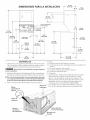
GASSUPPLYREQUIREMENTS ROUGH-IN DIMENSIONS
1. Installation MUST conform with local codes, or in the absence of
local codes, with the National Fuel Gas Code, ANSI Z223.1 (latest
edition) or in Canada, the current AN/CGA B149.
2.The gas supply line should be of 1/2 inch (1.27 cm) pipe.
3. If codes allow, flexible metal tubing may be used to connect your
dryer to the gas supply line. The tubing MUST be constructed of
stainless steel or plastic-coated brass.
4. The gas supply line MUST have an individual shutoff valve.
5. A 1/8 inch (0.32 cm) N. R T. plugged tapping, accessible for test
gage connection, MUST be installed immediately upstream of
the gas supply connection to the dryen
6.The dryer and its individual shutoff valve MUST be disconnected
from the gas supply piping system during any pressure testing of
the gas supply piping system at test pressures equal to or less
than 1/2 psig (3.45 kPa).
7.The dryer MUSTbe isolated from the gas supply piping system by
closing its individual manual shutoff valve during any pressure
testing of the gas supply piping system at test pressures
equal to or less than 1/2 psig (3.45 kPa).
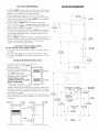
16 I/4 IN.
(41.27 CM)
LOCATION OF YOUR LAUNDRY CENTER
DO NOT INSTALL YOUR LAUNDRY CENTER:
1.In an area exposed to dripping water or outside weather
conditions.
2. In an area where it will come in contact with curtains or drapes.
3. On carpet. Floor MUST be solid with a maximum slope of 1 inch
(2.54 cm).
INSTALLATION IN RECESSOR CLOSET
1.A laundry center installed in a bedroom,
bathroom, recess or closet, MUST be
exhausted outdoors.
2. No other fuel burning appliance
shall be installed in the same closet
as the Gas laundry centen
3. Your laundry center needs the space
around it for proper ventilation.
DO NOT INSTALL YOUR
LAUNDRY CENTER IN A CLOSET
WITH A SOLID DOOR.
4. A minimum of 120 square
inches (774.2 square cm) of opening,
Closet Door
60 SQ. IN.
(387.1 SQ. CM)
60 SQ. IN.
(387.1 SQ. CM)
equally divided at the top and bottom of the door, is required. Air
openings are required to be unobstructed when a door is installed.
A louvered door with equivalent air openings for the full length
of the door is acceptable. 751/2(N.
5.The following illustrations show minimum clearance dimensions (191.77CM)
and air openings for proper operation in a recess or closet
installation.
36 1!161N.
(91.60 CM)
25 ¼IN.
i (64.13 CM)
_\\\\\\\
30 13/16 IN.
(78.26 CM)
2½IN.
(6.3SCM)
17/8 IN.
[_ (4.76CM)
(
+
11 7116 IN.
(29.5 CM)
4 13/16 iN.
(12.22 CM)
54 5/16 IN.
(137.95 CM)
12 I/2 IN._ 9 3/8 IN.
(31.75 CM_ (23.81 C_4)
VENT_.._ / -1_\ _,_
ELECTRICAL
CONNECTION ©
WATERINLETS _2_
(REAR)
43 IN.
(109.22 CM)
,m_ _ DRAINOUTLET
._,_ (REAR)
\J
3%1N.
_:---(9.52 CM)
27 IN.
(68.58CM)
f--GAS SUPPLY
PIPE (REAR)
s 1/4mN.
_13.33 CM)
1 43 IN.
/(109.22 CM)
411/4IN
I (104.77 CM)
29 7116 IN
(74.77CM)
"!

MOBILE HOME INSTALLATION
1.Dryer MUST be exhausted outside (outdoors, not beneath the mobile
home) using metal ducting that will not support combustion. Metal
ducting must be 4 inches (10.16 cm) in diameter with no obstructions.
Rigid metal duct is preferred.
2.If dryer isexhausted through the floor and area beneath the mobile
home isenclosed, the exhaust system MUSTterminate outside
the enclosure with the termination securely fastened to the mobile
home structure.
3.Refer to page 3 for other important venting requirements.
4.When installing a gas dryer into amobile home, a provision must be
made for outside make up air. This provision isto be not lessthan twice
the area of the dryer exhaust outlet.
5.Installation MUSTconform to current Manufactured Home Construction
& Safety Standard (which is a Federal Regulation Title 24 CFR-Part 32-
80) or when such standard is not applicable, with American National
Standard for Mobile Homes. In Canada, the CSA Z240 is applicable.
ii i
_iiiiiiiiiiiiiiiiiiiiiiiiiiiiiiiiiiiiiiiiiiiiiiiiiiiiiiiiiiiiiiiiiiiiiiiiiiiiiiiii
iiiiiiiiiiiiiiiiiiiiiiiiiiiiiiiiiiiiiiiiiiiiiiiiiiiiiiiiiiiiiiiiiiiiii
_1__ The laundry center is designed under ANSI Z 21.5.1for HOME USE only.
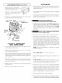
UNPACKING
1. Using the four shipping carton corner posts (two on each
side), carefully lay the laundry center on its left side and
remove foam shipping base.
Excessive weight. Use two or more people
to move Laundry Center.
2. Using a ratchet with 3/8 inch (0.96 cm) socket, remove the
mechanism shipping bolt and plastic spacer block from the
center of the base.
NOTE: If the laundry center is to be transported at a later
date, the tub blocking pad, shipping bolt, and plastic
spacer block should be retained.
3. Return laundry center to an upright position.
4. Remove:
(a) foam tub blocking pad.
(b) foam shipping blocks from rear of unit.
(c) tape from dryer door.
(d) foam dryer support pads.
(e) inlet hoses.
(f) enclosure package.
5. From the back of the washer, remove the wire shipping
clips securing the drain hose and power cord (if equipped).
Plastic clamps secure the drain hose to the right side of
the washer backsheet. These clamps form a standpipe to
prevent water syphoning. DO NOT REMOVE THESE
CLAMPS.
6. Carefully move the laundry center to within 4 feet (1.22 m)
of the final location to begin the installation.
PLASTIC SPACER
MECHANL €
SHIPPING
BOLT
CARTON CORNER POSTS
FOAM
SHIPPING
PAD
POWER CORD
(IF EQUIPPED)
DRAIN HOSE

ELECTRICAL INSTALLATION
i ALLELECTRICLaundryCenters ]
The following are specific requirements for
proper and safe electrical installation of your laundry center.
Failure to follow these instructions can create electrical shock
and/or a fire hazard.
This appliance MUST be properly grounded.
Electrical shock can result if the laundry center isnot properly
grounded. Follow the instructions in this manual for proper
grounding.
Do not use an extension cord with this
laundry center. Some extension cords are not designed to
withstand the amounts of electrical current this laundry center
utilizes and can melt, creating electrical shock and/or fire hazard.
Locate the laundry center within reach of the receptacle for the
length power cord to be purchased, allowing some slack in the
cord. Refer to the prednstallation requirements in this manual
for the proper power cord to be purchased.
A U.L.approved strain relief must be installed
onto power cord. If the strain relief isnot attached, the cord can
be pulled out of the laundry center and can be cut by any
movement of the cord, resulting in electrical shock.
I Canadian ELECTRICLaundry Center 1
I__lmproper connection of the equipment
grounding conductor can result in a risk of electrical shock,
Check with a licensed electrician if you are in doubt as to
whether the appliance is properly grounded.
Fora grounded cord connected laundry center:
1. The laundry center MUST be grounded. In the event of
malfunction or breakdown, grounding will reduce the risk of
electrical shock by providing a path of least resistance for
the electrical current.
2. Since your laundry center is equipped with a power supply
cord having an equipment-grounding conductor and a
grounding plug, the plug MUST be plugged into an
appropriate outlet that isproperly installed and grounded in
accordance with all codes and ordinances. If in doubt, call
a licensed electrician.
i
Do not use an aluminum wired receptacle
with a copper Wired power cord and plug (or vice versa). A
chemical reaction occurs between copper and aluminum and 2.
can cause electrical shorts. The proper wiring and receptacle
is a copper wired power cord with a copper wired
receptacle OR aluminum wired power cord with an 3.
aluminum wired receptacle.
NOTE: Laundry centers operating on a 208 volt power supply 4.
will have longer drying times than laundry centers operating on
a 240 volt power supply.
GROUNDING REQUIREMENTS
ALL GAS Laundry Centers
1
1.The laundry center isequipped with a three-prong (grounding)
plug for your protection against shock hazard and should
be plugged directly into a properly grounded three-prong
receptacle. Do not cut or remove the grounding prong from
the plug.
Non-Canadian ELECTRICl.aundry Center ]
Improper connection of the equipment
grounding conductor car/ result in a risk of electrical shock.
Check with a licensed electrician ifyou are in doubt asto whether
the appliance isproperly grounded.
For a qrounded, cord-connected laundry center:
1. The laundry center MUST be grounded. In the event of
malfunction or breakdown, grounding will reduce the risk of
electrical shock by a path of least resistance for electrical
current.
2. If your laundry center isequipped with a power supply cord
having an equipment-grounding conductor and a grounding
plug, the plug MUST be plugged into an appropriate, copper
wired receptacle that is properly installed and grounded in
accordance with all local codes and ordinances. If in doubt,
call a licensed electrician. Do not modify plug provided
with the appliance.
For a permanently connected laundry center:
The laundry center MUST be connected to a grounded metal,
permanent wiring system; or an equipment grounding conductor
MUST be run with the circuit conductors and connected to the
equipment-grounding terminal or lead on the appliance.
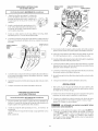
NON-CANADIAN ELECTRICLaundry Center j
Remove the screw securing the
terminal block access cover to
the rear panel and remove cover.
Install a U.L approved strain
relief connector in the entry
hole on the back panel.
Insert a NEMA 10-30 Type SRDT,
U.L approved power cord through the strain relief.
Attach the power cord neutral (central wire) conductor to
the silver colored center terminal on the terminal block.
Tighten the screw securely.
GREEN GROUND SCREW
SILVER TERMINAL
NEUTRAL
GROUND
WIRE
ELECTRICAL CONNECTIONS
FOR A 3-WIRE SYSTEM
5. Attach the remaining two power cord outer conductors to
the outer brass colored terminals on the terminal block.
Tighten both screws securely.
6. Tighten the screws securing the cord restraint against the
power cord.
7. Reinstall the terminal access cover.

NON-CANADIAN ELECTRICLaundry Center
1. Remove the screw securing the
terminal block access cover to the
rear panel and remove cover.
2. Install a U.L approved strain relief
connector in the entry hole on the
back panel.
J
3. Remove the neutral ground wire from the green ground
screw located above the termial block.
INSTALLATION
Run some water from the hot and cold faucets to flush the
water lines and remove particles that might clog up the
water valve screens.
.
3.
Check inlet hoses to ensure the rubber washers are installed
in each end.
Carefully connect the inlet hoses to the water valve (on the
left sideof the washer cabinet), tighten byhand, then tighten
another 2/3 turn with pliers.
GREEN GROUND GREEN
SCREW CONDUCTOR SILVER TERMINAL
TERMINAL BLOCK
NEUTRAL
GROUNQ
WIRE
BLACK
WHITE
STRAIN
RELIEF
MOUNTING
BRACKET,
POWER CORD
ELECTRICAL CONNECTIONS
FOR A 4-WIRE SYSTEM
4. Insert a NEMA 14-30 TypeSTor SRDT,U.L approved power
cord through the strain relief.
5. Attach the green power cord ground wire to the cabinet
with the green ground screw.
6. Attach the white (neutral) wire from the power cord and the
neutral ground wire from the appliance harnessto the silver
colored center terminal on the terminal block. Tighten the
screw securely.
7. Attach the red and black wires from the power cord to the
outer brass-colored terminals on the terminal block. Tighten
both screws securely.
8. Tighten the screws securing the cord restraint firmly against
the power cord.
9. Reinstall the terminal block access cover.
_ DO NOT CROSS THREAD OR
OVERTIGHTEN THESE CONNECTIONS.
4. Determine which water faucet isthe HOTwater faucet and
carefully connect the bottom inlet hose to the HOTwater
faucet, tighten by hand, then tighten another 2/3 turn with
pliers. Carefully connect the top inlet hose to the COLD
water faucet, tighten by hand, then tighten another 2/3 turn
with pliers.
DO NOT CROSS THREAD OR OVERTIGHTEN
THESE CONNECTIONS.
Turn the water on and check for leaks at both connections.
.
6.
Carefully move the laundry center to its final location.
To ensure the laundry center is level and solid on all four
legs, tilt the laundry center forward so the rear legs are off
the ground. Gently set the laundry center back down to
allow the rear legs to self adjust. Placea level on top of the
washer. Check it side to side, then front to back. Screw
the front leveling legs up or down to ensure the laundry
center is resting solid on all four legs (no rocking of the
laundry center should exist).
NOTE: Keep the leg extension at a minimum to prevent
excessive vibration.
7. GAS CONNECTION (Gas laundry centers only)
a.
b.
c.
d.
Remove the shipping cap from gas pipe at the rear of the
dryer.
NOTE: DO NOT connect the laundry center to L.R gas
service without converting the gas valve. An LR conversion
kit must be installed by a qualified gas technician.
Connect a 1/2 inch (1.27 cm) I.D. semi-rigid or approved
pipe from the gas supply line to the 3/8 inch (0.96 cm) pipe
located on the back of the dryer. Use a 1/2 inch (1.27 cm)
to 3/8 inch (0.96 cm) reducer for the connection. Apply an
approved thread sealer that is resistant to the corrosive
action of liquefied gases on all pipe connections.
Open the shutoff valve in the gas supply line.
Test all connections by brushing on a soapy water solution.
NEVER TEST FOR GAS LEAKS WITH AN OPEN FLAME.

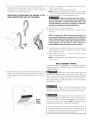
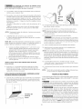
8. Form a " U " shape on the end of the drain hose with the
hose pointed toward the drain. Place the formed end in a
laundry tub or a standpipe and secure with a cable tie
provided in the enclosure package.
WATER WILL SYPHON FROM THE WASHER IF THE
ABOVE INSTRUCTIONS ARE NOT FOLLOWED.
9. Remove the two (2) screws securing the dryer front access
panel to the dryer cabinet. Lift the panel until the tabs can
be disengaged from the cabinet. Removethe panel and set
aside.
10. Connect the exhaust duct to outside duct work. Use duct
tape to seal all joints.
11. Plug the power cord into a grounded outlet.
NOTE: Check to ensure the power isoff at a circuit breaker/
fuse box before plugging the power cord into an outlet.
12. Turn on the power at a circuit breaker/fuse box.
Before operating the dryer, make
sure the dryer area is clear and free from combustible
materials, gasoline, and other flammable vapors. Also
see thatnothing (suchasboxes, clothing, etc.) obstructs
the How of combustion and ventilation air.
13. Reinstall the dryer front access panel.
14. Runthe washer and dryer though a cycle. Check for proper
operation.
NOTE: On gas dryers, before the burner will light, it is
necessary for the gas line to be bled of air. If the burner
does not lightwithin 45 seconds the first time the dryer
b turned on, the safety switch will shut the burner off.
If this happens, turn the timer to "OFF" and wait 5
minutes before making another attempt to light.
15. If your laundry center does not operate, please review the
"Avoid Service Checklist" located in your Owner's Guide
before calling for service.
16. Place these instructions in a location near the laundry
center for future reference.
NOTE: A wiring diagram is located behind the dryer front
access panel.
REPLACEMENT PARTS
If replacement parts are needed for your Laundry Center, call
SearsParts and ServiceToll FreeNumber 1-800-4-MY-HOMF M
(1-800-469-4663).
Destroy the carton, plastic bags, and metal
band after the laundry center isunpacked. Children might use
them for play. Cartons covered with rugs, bedspreads, or plastic
sheets can become airtight chambers causing suffocation.
Place all materials in a garbage container or make materials
inaccessible to children.
Access
Panel
Screws
Label all wires prior to disconnection when
servicing controls. Wiring errors can cause improper and
dangerous operation. Verify proper operation after servicing.
I__ The instructions in this manual and all other
literature included with this laundry center are not meant to
cover every possible condition and situation that may occur.
Good safe practice and caution MUST be applied when
installing, operating and maintaining any appliance.
Maximum benefits and enjoyment are achieved when all
the Safety and Operating instructions are understood and
practiced asa routine with your laundry tasks.
Page is loading ...
Page is loading ...
Page is loading ...
Page is loading ...
Page is loading ...
Page is loading ...
Page is loading ...

Your Home
For repair-in your home-of all major brand appliances,
lawn and garden equipment, or heating and cooling systems,
no matter who made it, no matter who sold it!
For the replacement parts, accessories and
owner's manuals that you need to do-it-yourself.
For Sears professional installation of home appliances
and items like garage door openers and water heaters.
1-800-4-MY-HOME ® (1-800-469-4663)
Call anytime, day or night (U.S.A. and Canada)
www,sears,com www.sears.ca
Our Home
For repair of carry-in items like vacuums, lawn equipment,
and electronics, call or go on-line for the location of your nearest
Sears Parts & Repair Center.
1-800-488-1222
Call anytime, day or night (U.S.A. only)
www.sears.com
To purchase a protection agreement (U.S.A.)
or maintenance agreement (Canada) on a product serviced by Sears:
1-800-827-6655 (U.S.A.) 1-800-361-6665 (Canada)
Para pedir servicio de reparaci6n
a domicilio, y para ordenar piezas:
1-888-SU-HOGAR sM
(1-888-784-6427)
Au Canada pour service en frangais:
1-800-LE-FOYER Mc
(1-800-533-6937)
www.sears.ca
Ses./rs
TM SM
® Registered Trademark / Trademark / Service Mark of Sears, Roebuck and Co.
® Marca Registrada / TMMarca de F&brica / s_4Marca de Servicio de Sears, Roebuck and Co.
MD
MCMarque de commerce / Marque dCpos_e de Sears, Roebuck and Co. ® Sears, Roebuck and Co.
-
 1
1
-
 2
2
-
 3
3
-
 4
4
-
 5
5
-
 6
6
-
 7
7
-
 8
8
-
 9
9
-
 10
10
-
 11
11
-
 12
12
-
 13
13
-
 14
14
-
 15
15
-
 16
16


Ask a question and I''ll find the answer in the document
Finding information in a document is now easier with AI
in other languages
Related papers
-
Kenmore 41797912702 Installation guide
-
-
 Kenmore Elite 11092966100 Owner's manual
-
-
-
Kenmore 110C81432510 Owner's manual
-
 Kenmore Elite Kenmore 27-1nch Wide - Extra Large Capacity Plus LAUNDRY CENTER Washer - Electric Dryer Owner's manual
-
-
Sears 6418 - 5.7 cu. Ft. Coin Operated Electric Dryer User manual
-
 Kenmore Elite 11060052990 Owner's manual


Other documents
-
Frigidaire FLXG52RBSA Installation guide
-
Electrolux EIMED55IMB3 Installation guide
-
Crosley SWXG831HS2 Installation guide
-
Crosley FFLE39C1QW0 Installation guide
-
Frigidaire FLXG52RBSA Installation guide
-
Frigidaire FFLE3900UW Installation guide
-
Universal/Multiflex (Frigidaire) GCET1031FS4 Installation guide
-
-
Electrolux SAGQ7000FS0 Installation guide
-
Frigidaire GLEQ2152ES0 Installation guide