Rev 1 Page 1 of 6 10125186
PrimaX™ IR Link
General Information
and
Help Guide
The information in this Help file is specific to the PC software that interfaces with the
PrimaX IR Gas Monitor. Please refer to the PrimaX IR Gas Monitor User’s Manual on
the Product CD for detailed Gas Monitor installation and operating instructions.
This Help Guide is available on the Internet at www.msanet.com

Rev 1 Page 2 of 6 10125186
Overview - Getting started
This software is designed to allow a user to configure and communicate with an MSA
PrimaX IR gas monitor. This software is intended to run on a Microsoft Windows
computer. The following hardware is needed:
• PrimaX IR monitor with 24volt DC power supply
• Computer with Windows operating system (Windows XP or newer)
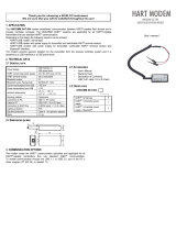
• USB HART modem
• 250Ω resistor
The resistor is to be placed in the current loop output of the instrument (between the mA
analog output and DC-). See the Quick Start Guide or User’s Manual for the installation
wiring diagram. The HART modem attaches across the resistor to enable two way
communications between the computer and the instrument.
When starting the program for the first time, the user may need to select the
communications port from the pull down menu. If communications do not start
automatically with the default port, use the pull down menu (EDIT – COMM PORT
SELECT) to find the port assigned by the computer to the HART modem.
PrimaX IR Link Installation
To install the PrimaX IR Link software, select the executable file on the Product CD.
The application requires that .Net Framework v2.0 or higher is installed on the host
computer. The PrimaX IR Link installation file will check the computer to verify if .Net
Framework is installed. If not, the application will prompt the user to allow automatic
installation of .Net Framework. Start the application from the desktop icon.
HART
Modem
USB to
computer
R
R=250Ω

Rev 1 Page 3 of 6 10125186
Screen Information
When the application is loaded, the following screen will appear:
Status:
The COMM ACTIVITY indicator will flash when the computer and instrument are
communicating.
GAS VALUE shows the live LEL reading of the instrument. Note that due to the speed
of HART communications, the update will take several seconds to update between
readings.
LOOP CURRENT shows the live analog output commanded by the instrument.
UNIT STATUS shows the current state of the instrument (ie Normal, Fault, etc)
Unit settings:
SERIAL NUMBER is unique identifier that is factory set and cannot be changed by the
user.
UNIT DESCRIPTOR is an identification field that can be updated by the user.
GAS CURVE can be changed by the user to match the intended target gas application,
note that the user must calibrate the instrument if the gas curve is changed.

Rev 1 Page 4 of 6 10125186
GAS NAME will default to a predefined name once a gas curve is chosen but the user
can then rename the gas, note that renaming the gas does not change the gas curve.
SPAN VALUE is a user-settable number that represents the LEL value of the calibration
gas to be used.
FAULT LEVEL, OBSCURATION LEVEL, START/CAL LEVEL, and CLEANING MODE
LEVEL are the milliamp levels that the instrument will output during that particular
condition, note that these values can be changed by the user as described in the
Operating Manual.
CALIBRATION STATUS shows the results of the most recent zero and span
calibrations in addition to the status as to whether the calibration cap is attached. Note
that if the zero and/or span result shows as failed, the unit will continue to operate using
the previous calibration values which passed.
Commands
After sending any of these commands, verify that the changes were implemented on
PrimaX IR Link.
‘START CALIBRATION’ BUTTON - initiates a zero or a full calibration (zero and span).
‘SEND COMMAND’ BUTTON enables the commands shown below. Note that the
white text box gives the user feedback when executing commands.
START CALIBRATION – performs a zero or a full calibration (zero and span)
WRITE TAG, DESCRIPTOR, DATE – updates HART tag information, the user
descriptor and the date field. Note that all of these are simply place holder text fields
and are not updated or modified by the instrument.
WRITE SPAN VALUE – changes the span value. This is the LEL value for the
calibration gas of which the instrument expects to see during calibration. Note that the
user should calibrate the instrument if changing this value.
WRITE GAS CURVE – changes gas curve used by and stored within the instrument for
a particular gas or class of gases. Note that changing the gas curve sets the linearity of
a particular gas response. Once the gas curve is changed, the instrument must be
calibrated to the expected span value before it is put into operation.
WRITE GAS NAME – changes the displayed name for the gas, after the gas curve is
selected. Note that when a new gas curve is selected, the gas name will be reset to the
factory default name for that gas curve. This does not affect the gas curve selection or
the span value
WRITE LOOP SIGNAL LEVELS – changes the output mA values that the instrument
uses for various states of operation including fault, obscuration, startup and calibration,
cleaning mode.

Rev 1 Page 5 of 6 10125186
CALIBRATION SIGNAL CONTROL– enables or disables the calibration signal. When
enabled, the analog output will be set to a fixed value during a calibration, as defined by
the Write Loop Signal Levels command. If disabled, the analog output will follow the
actual gas reading during a calibration.
READ ADDITIONAL DEVICE STATUS – polls the instrument for various internal status
flags that can be used for troubleshooting.
ENTER/EXIT FIXED CURRENT MODE – sets the analog output at a fixed value (ie 4.0
mA). Note that if the user does not exit fixed current mode, the instrument will
automatically exit the mode after approximately 15 minutes, or if power is removed.
TRIM LOOP CURRENT ZERO – makes minor adjustments to the 4mA analog output
setting. Note that execution of this command requires the user to first enter fixed
current mode and to have the fixed current set to 4.0mA.
TRIM LOOP CURRENT GAIN – makes minor adjustments to the 20mA analog output
setting. Note that execution of this command requires the user to first enter fixed
current mode and to have the fixed current set to 20.0mA.
CALIBRATION ABORT – exits an active calibration if executed during the initial 30
seconds of the calibration procedure. If calibration is aborted, the unit will continue to
operate using the previous calibration values which passed.
PERFORM DEVICE SOFTWARE RESET – performs a soft reboot of the instrument
operating system without the need to remove power.
READ UNIQUE IDENTIFIER – reads identification information from the instrument. This
command is used to read the software version number.
Troubleshooting
1. Check that instrument DC power is connected and is sufficient by observing the
flashing lights used by the instrument for operation.
2. Ensure HART modem software driver which is supplied from the modem
manufacturer, has been installed on the computer.
3. Check that the HART modem connections are secure at computer and instrument.
4. Check that the HART modem clip leads are attached across the 250 ohm resistor
and that the resistor is connected in series with the analog output signal.
5. Check that the correct computer communications port (COM1, COM2, etc) is
selected using the software pull down menu.
6. If having trouble with USB communications try unplugging the USB connector at the
computer, re-plugging it in and then reselect the COM port.
7. See command above (READ ADDITIONAL DEVICE STATUS) for additional
information.

Rev 1 Page 6 of 6 10125186
MINE SAFETY APPLIANCES COMPANY
CRANBERRY TOWNSHIP, PENNSYLVANIA, USA 16066
1-800 –MSA-INST www.msanet.com
/