Panasonic TH42PA20M Owner's manual
- Category
- LCD TVs
- Type
- Owner's manual
This manual is also suitable for

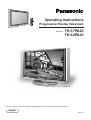
Operating Instructions
Progressive Plasma Television
TH-37PA20
TH-42PA20
Model No.
TQBC0645
Please read these instructions before operating your set and retain them for future reference.
English
1
2 3
4
5 6
7
8 9
0
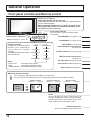
Pedestal stand shown above is optional extra.

2
Dear Panasonic Customer
Welcome to the Panasonic family of customers. We hope that you will have many years of
enjoyment from your new Plasma TV.
To obtain maximum benefit from your set, please read these Instructions before
making any adjustments, and retain them for future reference.
Retain your purchase receipt also, and note down the model number and serial
number of your set in the space provided on the rear cover of these instructions.

3
Table of Contents
Important Safety Notice ............................................ 4
Safety Precautions .................................................... 5
Supplied Accessories ............................................... 7
Fitting remote control batteries ................................ 7
Battery cautions ....................................................... 7
Cable Connection...................................................... 8
Antenna Connection ................................................ 9
AV & COMPONENT Connection............................ 10
Headphones / AV3 terminals Connection............... 11
PC Input terminals Connection .............................. 12
Power ON / OFF ....................................................... 13
AC cord Connection ............................................... 13
Power On/Off ......................................................... 13
General Operation ................................................... 14
Front panel controls and Remote control ............... 14
Using the On Screen Displays ............................... 16
Tuning Channels ..................................................... 18
Channel Selection ................................................. 18
Channel Allocation ................................................. 19
Auto Tune ............................................................... 20
Auto Tune (via front panel)..................................... 20
Manual Tune .......................................................... 21
Manual Tune (via front panel) ................................ 21
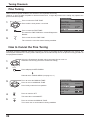
Fine Tuning ............................................................ 22
How to Cancel the Fine Tuning .............................. 22
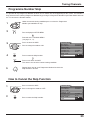
Programme Number Skip ...................................... 23
How to Cancel the Skip Function .......................... 23
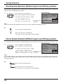
Sound System Selection
(Different region use differing systems) ...... 24
Colour System Selection
(Different region use differing systems) ...... 24
Owner ID .................................................................. 25
Setup Adjustment ................................................... 26
TELETEXT ............................................................. 26
OFF TIMER ............................................................ 26
CH COLOUR SET ................................................. 26
CHILD LOCK ......................................................... 26
TEXT SELECT ....................................................... 26
SIDE PANEL .......................................................... 26
POWER SAVE ....................................................... 26
LANGUAGE ........................................................... 26
VCR/GAME ............................................................ 26
COLOUR SYSTEM ................................................ 26
Picture Adjustment ................................................. 27
Sound Adjustment .................................................. 29
Channel Search ....................................................... 30
Aspect Controls ...................................................... 31
PC mode Adjustments ............................................ 32
Advanced settings .................................................. 33
Adjusting Position and Size ................................... 34
Multi Screen ............................................................. 35
Multi PIP ................................................................. 35
TELETEXT ................................................................ 36
Advanced Remote Control Operation ................... 39
Stereo Bilingual Sound Selection ........................... 39
VCR / DVD Control ................................................ 39
Manufacturer setting .............................................. 40
Troubleshooting ...................................................... 41
For your Guidance .................................................. 42
Input signal can be displayed ................................ 42
Specifications .......................................................... 43

4
WARNING
1) To prevent damage which may result in fire or shock hazard, do not expose this appliance to rain or
moisture.
Do not place containers with water (flower vase, cups, cosmetics, etc.) above the set. (including on
shelves above, etc.)
2) To prevent electric shock, do not remove cover. No user serviceable parts inside. Refer servicing to qualified
service personnel.
3) Do not remove the earthing pin on the power plug. This apparatus is equipped with a three pin earthing-type
power plug. This plug will only fit an earthing-type power outlet. This is a safety feature. If you are unable to
insert the plug into the outlet, contact an electrician.
Do not defeat the purpose of the earthing plug.
Important Safety Notice
CAUTION
This appliance is intended for use in environments which are relatively free of electromagnetic fields.
Using this appliance near sources of strong electromagnetic fields or where electrical noise may overlap with the
input signals could cause the picture and sound to wobble or cause interference such as noise to appear.
To avoid the possibility of harm to this appliance, keep it away from sources of strong electromagnetic fields.
To prevent electric shock, ensure the grounding pin on the AC cord power plug is securely connected.
Trademark Credits
•
VGA is a trademark of International Business Machines Corporation.
•
Macintosh is a registered trademark of Apple Computer, USA.
•
S-VGA is a registered trademark of the Video Electronics Standard Association.
Even if no special notation has been made of company or product trademarks, these trademarks have been fully
respected.
Symptom
After-images appear
CAUTION:
Check
Do not allow a still picture to be displayed for an extended period, as this can
cause a permanent after-image to remain on the Plasma TV.
Examples of still pictures include logos, video games, computer images, teletext
and images displayed in 4:3 mode.
Note:
The permanent after-image on the Plasma TV resulting from fixed image use is
not an operating defect and as such is not covered by the Warranty.
This product is not designed to display fixed images for extended periods of time.

5
Safety Precautions
WARNING
Setup
This Plasma TV is for use only with the following optional accessories. Use with any other type of optional
accessories may cause instability which could result in the possibility of injury.
(All of the following accessories are manufactured by Matsushita Electric Industrial Co., Ltd.)
•
Pedestal ............................................... TY-ST42PA20
•
Display stand ....................................... TY-S42PA20W (TH-42PA20), TY-S37PA20W (TH-37PA20)
•
Wall-hanging bracket (vertical) ............ TY-WK42PV2W
Always be sure to ask a qualified technician to carry out set-up.
Do not place the Plasma TV on sloped or unstable surfaces.
•
The Plasma TV may fall off or tip over.
Do not place any objects on top of the Plasma TV.
•
If water is spilt onto the Plasma TV or foreign objects get inside it, a short-circuit may occur which could result in
fire or electric shock. If any foreign objects get inside the Plasma TV, please consult your local Panasonic dealer.
If using the pedestal (optional accessory), leave a space of at least 10 cm at the top, left and right, at least 6
cm at the bottom, and at least 7 cm at the rear. If using some other setting-up method, leave a space of at
least 10 cm at the top, bottom, left and right, and at least 1.9 cm at the rear.
Avoid installing this product near electronic equipment that is easy to receive electromagnetic waves.
•
It will cause interference in image, sound, etc. In particular, keep video equipment away from this product.
When using the Plasma TV
The Plasma TV is designed to operate on 220 - 240 V AC, 50/60 Hz.
Do not cover the ventilation holes.
•
Doing so may cause the Plasma TV to overheat, which can cause fire or damage to the Plasma TV.
Do not stick any foreign objects into the Plasma TV.
•
Do not insert any metal or flammable objects into the ventilations holes or drop them onto the Plasma TV, as
doing so can cause fire or electric shock.
Do not remove the cover or modify it in any way.
•
High voltages which can cause severe electric shocks are present inside the Plasma TV. For any inspection,
adjustment and repair work, please contact your local Panasonic dealer.
Securely insert the power cord plug as far as it will go.
•
If the plug is not fully inserted, heat may be generated which could cause fire. If the plug is damaged or the wall
socket plate is loose, they shall not be used.
Do not handle the power cord plug with wet hands.
•
Doing so may cause electric shocks.
Do not do anything that may damage the power cable. When disconnecting the power cable, pull on the plug
body, not the cable.
•
Do not damage the cable, make any modifications to it, place heavy objects on top of it, heat it, place it near any
hot objects, twist it, bend it excessively or pull it. To do so may cause fire and electric shock. If the power cable
is damaged, have it repaired at your local Panasonic dealer.
If the Plasma TV is not going to be used for any prolonged length of time, unplug the power cord plug from
the wall outlet.

6
Safety Precautions
If problems occur during use
If a problem occurs (such as no picture or no sound), or if smoke or an abnormal odour starts to come out
from the Plasma TV, immediately unplug the power cord plug from the wall outlet.
•
If you continue to use the Plasma TV in this condition, fire or electric shock could result. After checking that the
smoke has stopped, contact your local Panasonic dealer so that the necessary repairs can be made. Repairing
the Plasma TV yourself is extremely dangerous, and shall never be done.
If water or foreign objects get inside the Plasma TV, if the Plasma TV is dropped, or if the cabinet becomes
damages, disconnect the power cord plug immediately.
•
A short circuit may occur, which could cause fire. Contact your local Panasonic dealer for any repairs that need to
be made.
CAUTION
When using the Plasma TV
Do not bring your hands, face or objects close to the ventilation holes of the Plasma TV.
•
Heated air comes out from the ventilation holes at the top of Plasma TV will be hot. Do not bring your hands or
face, or objects which cannot withstand heat, close to this port, otherwise burns or deformation could result.
Be sure to disconnect all cables before moving the Plasma TV.
•
If the Plasma TV is moved while some of the cables are still connected, the cables may become damaged, and fire
or electric shock could result.
Disconnect the power cord plug from the wall socket as a safety precaution before carrying out any cleaning.
•
Electric shocks can result if this is not done.
Clean the power cable regularly to prevent it becoming dusty.
•
If dust built up on the power cord plug, the resultant humidity can damage the insulation, which could result in fire.
Pull the power cord plug out from the wall outlet and wipe the mains lead with a dry cloth.
This Plasma TV radiates infrared rays, therefore it may affect other infrared communication equipment.
Install your infrared sensor in a place away from direct or reflected light from your Plasma TV.
Cleaning and maintenance
The front of the display panel has been specially treated. Wipe the panel surface gently using only a cleaning
cloth or a soft, lint-free cloth.
•
If the surface is particularly dirty, wipe with a soft, lint-free cloth which has been soaked in pure water or water to
which a small amount of neutral detergent has been added, and then wipe it evenly with a dry cloth of the same
type until the surface is dry.
•
Do not scratch or hit the surface of the panel with fingernails or other hard objects, otherwise the surface may
become damaged. Furthermore, avoid contact with volatile substances such as insect sprays, solvents and thinner,
otherwise the quality of the surface may be adversely affected.
If the cabinet becomes dirty, wipe it with a soft, dry cloth.
•
If the cabinet is particularly dirty, soak the cloth in water to which a small amount of neutral detergent has been
added and then wring the cloth dry. Use this cloth to wipe the cabinet, and then wipe it dry with a dry cloth.
•
Do not allow any detergent to come into direct contact with the surface of the Plasma TV.
If water droplets get inside the unit, operating problems may result.
•
Avoid contact with volatile substances such as insect sprays, solvents and thinner, otherwise the quality of the
cabinet surface may be adversely affected or the coating may peel off. Furthermore, do not leave it for long
periods in contact with articles made from rubber or PVC.

7
1
2 3
4
5 6
7
8 9
0
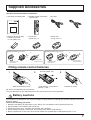
Supplied Accessories
•
Operating Instruction book
•
Remote Control Transmitter
(EUR511281)
•
AC cord
•
Batteries for the Remote
Control Transmitter
(2 × R6 (UM3) size)
Check the accessories before installations.
Slide off the battery cover Insert batteries - note correct
polarity (+ and -)
Replace the cover
Fitting remote control batteries
123
Two “R6 (UM3)” size
•
Ferrite core
(Small size) × 5
•
Ferrite core
(Large size) × 3
Installing the ferrite core (Small size)
Pull back the tabs
(in two places)
Open
Press the cable
through and close
1
2
3
Installing the ferrite core (Large size)
Pull back the tabs
(in two places)
Open
Press the cable
through and close
1
2
3
The incorrect use of batteries can cause electrolyte leakage which will corrode the Remote Control or cause the
batteries to burst.
Observe the following precaution:
1. Batteries shall always be replaced as a pair. Always use new batteries when replacing the old set.
2. Do not combine a used battery with a new one.
3. Do not mix battery types (example:“Zinc Carbon” with “Alkaline”).
4. Do not attempt to charge, short-circuit, disassemble, heat or burn used batteries.
5. Battery replacement is necessary when remote control acts sporadically or stops operating the TV set.
Battery cautions
Do not use rechargeable (Ni-Cd) batteries.
They are different in shape and performance and may fail to ensure correct operation.

8
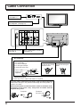
Cable Connection
S VIDEO VIDEO
AV 3
L R
PC
S-VIDEO
PC
CHANNELVOLUMEACTIONINPUT
HPJ
VIDEO
VIDEO
3
R AUDIO L
MONITOR
OUT
AV1
IN
COMPONENT COMPONENT
S VIDEO
MONO
VIDEO
P
B
L
YY
R
P
R
P
B
P
R
AUDIO
MONO MONO
AV2 IN AV4 IN
Front AV terminals
(see page 11)
From EXTERNAL monitor terminal
on Computer (see page 12)
1
3
2
4
ANTENNA IN terminal
(see page 9)
AV & COMPONENT terminals
(see page 10)
– AC cord fixing
1. Connect power plug to the socket of
the main body.
2. Fix the left clamper.
3. Fix the right clamper.
4. Install the ferrite core.
Ferrite core
(Large size)
(supplied)
How to fix: Fix by
pushing in till a clicking
sound is heard.
How to release: Pull
up while drawing the
knob.
– Cable fixing bands
Secure any excess cables with bands as required.
To secure cables connected to Terminals, wrap the cable fixing band
around them then pass the pointed end through the locking block, as
shown in the figure.
While ensuring there is sufficient slack in cables to minimize stress
(especially in the power cord), firmly bind all cables with the
supplied fixing band.
To tighten:
Pull
To loosen:
Push the catch
Pull

9
MONITOR
OUT
AV1
IN
COMPONENT COMPONENT
S VIDEO
MONO
VIDEO
PB
L
YY
R
PR
PB
PR
AUDIO
MONO MONO
AV2 IN AV4 IN
ANT INPUT
ANT OUTPUT
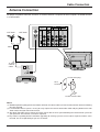
Cable Connection
Antenna Connection
Notes:
(1) To obtain optimum quality picture and sound, an Aerial, the correct cable (75 Ohm coaxial) and the correct terminating
plug are required.
(2) If a communal Aerial system is used, you may require the correct connection cable and plug between the wall
Aerial socket and your television receiver.
(3) Your local Television Service Centre or Dealer may be able to assist you in obtaining the correct Aerial system for
your particular area and the accessories required.
(4) Any matters regarding Aerial installation, upgrading of existing systems or accessories required, and the costs
incurred, are the responsibility of you, the Customer.
For proper reception of VHF/UHF channels, an external antenna is required. For best reception, an outdoor antenna
is recommended.
VHF Aerial
UHF Aerial
Mixer
75 Ohm
Coaxial
Cable
VCR
OR
RF in
Terminal
Coaxial aerial plug
75 Ohm Coaxial Cable

10
Cable Connection
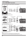
AV & COMPONENT Connection
Notes:
• Change the input signal to use the colour buttons on the remote control. (see page 17)
• Additional equipment, cables and adapter plugs shown are not supplied with this set.
• When a Monaural VCR is used, connect the Monaural Audio cable to the Audio “L”(Left) terminal.
AV1 IN
AV2 IN or
AV4 IN
MONITOR
OUT
MONO
AUDIO
IN
VIDEO
IN
L
R
VIDEO
OUT
AUDIO
OUT
Y, P
B
,
P
R
,
OUT
P
R
P
B
Y
P
R
P
B
Y
L
R
COMPONENT VIDEO OUT
VIDEO
OUT
S VIDEO
OUT
AUDIO
OUT
R
L
MONITOR
OUT
AV1
IN
COMPONENT COMPONENT
S VIDEO
MONO
VIDEO
P
B
L
YY
R
P
R
P
B
P
R
AUDIO
MONO MONO
AV2 IN AV4 IN
MONITOR
OUT
AV1
IN
COMPONENT COMPONENT
S VIDEO
MONO
VIDEO
P
B
L
YY
R
P
R
P
B
P
R
AUDIO
MONO
MONO MONO
AV2 IN AV4 IN
MONITOR
OUT
AV1
IN
COMPONENT COMPONENT
S VIDEO
MONO
VIDEO
P
B
L
YY
R
P
R
P
B
P
R
AUDIO
MONO MONO
AV2 IN AV4 IN
MONITOR
DVD
S VIDEO VCR
CAMCORDER
VCR
Example of output
signal source
Example of input
signal source
Digital TV-SET-TOP-BOX
(DTV-STB)
VCR
Example of input
signal source
Amplifier to speaker
system
Connect the S-VIDEO or
VIDEO terminal
How to connect the Monitor Output Terminals to other Equipment
How to connect the AV1 Input Terminals
How to connect the DVD Input Terminals

11
Cable Connection
S VIDEO
R - STANDBY
G - POWER ON
STR F TV/AV
AV3
VIDEO L R/ /
Camcorder
(Not supplied)
(Optional)
(
3.5 mm plug
)
Less than
4" (10 cm)
S VIDEO
AV3
VIDEO PCL R
Less than
4" (10 cm)
Ferrite core (Small size)
(supplied)
AV3 S VIDEO 4 pin socket
Luminance earth
Luminance in
Chrominance in
Chrominance earth
VIDEO
OUT
S VIDEO
OUT
AUDIO
OUT
R
L
Connect the S-VIDEO or VIDEO terminal
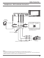
Headphones / AV3 terminals Connection
Notes:
• Change the input signal to use the colour buttons on the remote control. (see page 17)
• The volume level of the headphones can be adjusted by selecting “HEADPHONE VOL.” from the SOUND menu.
• Additional equipment and cables shown are not supplied with this set.
A camcorder uses the AV3 terminal
on the front of this set.

12
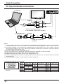
Cable Connection
PC Input terminals Connection
S VIDEO VIDEO
AV 3
L R
PC
COMPUTER
Conversion adapter
(if necessary)
RGB
D-sub 15p
Stereo plug
PC cable
Connect a cable which matches
the audio output terminal on the computer.
Less than
4" (10 cm)
Ferrite core (Small size)
(supplied)
Ferrite core (Large size)
(supplied)
Audio
Less than
4" (10 cm)
Less than
4" (10 cm)
Notes:
(1) Computer signals which can be input are those with a horizontal scanning frequency of 15 to 110 kHz and vertical
scanning frequency of 48 to 120 Hz. (However, the image will not be displayed properly if the signals exceed 1,200 lines.)
(2) The display resolution is a maximum of 640 × 480 dots when the aspect mode is set to “4:3”, and 852 × 480 dots
when the aspect mode is set to “16:9”. If the display resolution exceeds these maximums, it may not be possible
to show fine detail with sufficient clarity.
(3) Some PC models cannot be connected to the set.
(4) There is no need to use an adapter for computers with DOS/V compatible D-sub 15P terminal.
(5) The computer shown in the illustration is for example purposes only.
(6) Additional equipment and cables shown are not supplied with this set.
(7) Do not set the horizontal and vertical scanning frequencies for PC signals which are above or below the specified
frequency range.
(8) The Sound of the PC mode is combined with the Audio signal of AV3.
Signal Names for D-sub 15P Connector
Pin Layout for PC Input
Terminal
Pin No.
1
2
3
4
5
Pin No.
6
7
8
9
10
Pin No.
11
12
13
14
15
Signal Name
R
G
B
NC (not connected)
GND (Ground)
Signal Name
GND (Ground)
GND (Ground)
GND (Ground)
NC (not connected)
GND (Ground)
Signal Name
NC (not connected)
NC
HD/SYNC
VD
NC
1
678
3
9
45
10
15 14 13 12 11
2

13
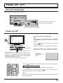
Power ON / OFF
AC cord Connection
Connecting the AC cord plug to the Plasma TV.
Ferrite core (Large size) (supplied)
Fix the AC cord plug securely to the
Plasma TV with the clamper.
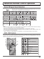
Remote Control Sensor
Power Indicator
Press the button on the remote control to turn the Plasma TV to standby.
Power Indicator: Red (standby)
Press the button on the remote control to turn the Plasma TV on.
Turn the Plasma TV set off by pressing the switch on the Plasma TV,
when the Plasma TV is on or in standby mode.
C.A.T.S sensor
Plasma C.A.T.S (Contrast Automatic Tracking System)
Plasma C.A.T.S automatically senses the ambient light
conditions and adjusts the brightness and gradation
accordingly, to optimise contrast.
(Effective when Viewing mode is set to Auto.)
For VIDEO /
COMPONENT / TV
INPUT:
Note:
The unit will still consume some power as long as the mains lead is still inserted
into the mains outlet.
Power On/Off
1
TV/AV
PICTURE
SOUND
SET UP
Connect the plug to the Wall Outlet
Note:
Main plug types vary between countries. The power
plug shown at left may, therefore, not be the type fitted
to your set.
Press the switch on the Plasma TV to turn the
set on: Power-On.
Owner ID setting screen is displayed. (see page 25)
From the second time on, the below screen is
displayed for a while (setting condition is an example).

14
S VIDEO
R - STANDBY
G - POWER ON
STR F TV/AV
AV3
VIDEO L R/ /
STR F TV/AV/ /
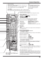
N (Normalise) button
Resets all settings to their default leves
General Operation
Front panel controls and Remote control
PICTURE Menu (see page 27, 28)
SOUND Menu (see page 29, 30)
SETUP Menu (see page 26)
Surround On or Off (see page 30)
Aspect Control (see page 31)
PC input button (see page 32-34)
Stereo Bilingual Sound Selection
(see page 39)
Function selection
Displays the On Screen Display
functions, press repeatedly to
select from the available
functions.
The following adjustments can be
accessed directly.
VOLUME
CONTRAST
BRIGHTNESS
COLOUR
SHARPNESS
TUNING MODE
BALANCE
TREBLE
BASS
NTSC-TINT
(TINT)
Notes:
• NTSC-TINT : Receiving NTSC signals.
• TINT : Receiving YUV(60Hz) signals.
• TUNING MODE : Not displayed during AV mode.
Plasma TV On / Off Switch
Store (see page 17, 20-25, 37)
Volume Up (+), Down (-)/
Programme Number Up ( ), Down ( )
Volume adjustment which uses these buttons is performed after
pressing Function button.
When programme number up ( ) or down ( ) button on the
front panel of the Plasma TV is pressed in stand-by mode,
the Plasma TV will be turned on.
TV/AV mode Selection
Press to select TV, AV input signal modes
sequentially.
TV/TEXT Selection (see page 36-38)
TEXT Favourite Page Selection
(see page 37)
Recall
Press to display the current system status, for
example, Programme number, Channel number,
Stereo mode, Picture menu, Sound menu, Scan
mode, Sound system and colour system.
AB
A
B
A
B
MULTI
PIP
MULTI PIP (Picture In Picture)
Press to display main picture and sub picture (see page 35).
The main picture and sub picture can be changed by using Red, Green and Blue buttons.
[Picture out of Picture]
main picture sub picture
[Picture and Picture] [Picture in Picture]
Normal
Viewing
main picture sub picture main picture sub picture
MULTI
PIP

15
N
DVD
REC
-
VCR
STR
TV/AV
1 2 3
4 5 6
7 8 9
F.P.
INDEX HOLD
CH SEARCH
STILL
PICTURE
SOUND
SET UP
TV/TEXT
ASPECT
0
MULTI
PIP
PC
SURROUND
Store (see page 17, 20-25, 37)
Stores some settings in TUNING MENU
and TELETEXT.
Power (Stand-by)
The TV set must first be plugged into the wall outlet and
turned on at the power switch.
Press this button to turn the TV set On from Standby mode,
Press it again to turn the TV set to Standby mode.
Note:
It is also possible to turn the TV set
on from Standby mode by pressing
the “Direct Programme Number
Selection” Buttons (0-9) on the
remote control.
Sound Mute
Press to mute the sound completely the “Mute” symbol will appear.
Press again to restore the previous sound level, and cancel the mute.
Programme Number Selection
Press to select the next higher or lower Programme number.
Volume Adjustment
Press to increase or decrease the sound volume level.
VOLUME 23
TV/AV Mode Selection
Press to select TV, AV input signal modes sequentially.
TEXT Hold
(see page 37)
STILL
Press to freeze the picture, press again to return to watching the
current programme.
Coloured buttons used for
• AV Selection (see page 17)
• Channel Search (see page 30)
• Aspect Controls (see page 31)
• Multi PIP (see page 35)
•
TELETEXT functions (see page 36-38)
General Operation
VCR / DVD Operation (see page 39)
The Remote Control is capable of operating some functions of
selected VCR’s and DVD (Digital Versatile Disc) equipment. Some
VCR and DVD equipment have different functions, so to ensure
compatibility please refer to the equipment's instruction book or
consult your dealer for details.
TEXT Index
(see page 38)
Channel Search
(see page 30)
Direct programme Number
• Direct Programme Number Selection
(CH SELECT = DIRECT)
You can select the number directly by pressing the corresponding
programme number buttons.
Programme Number 8.......
8
Programme Number 36.....
3
,
6
Programme Number 124...
1
,
2
,
4
• Direct Programme Number Selection
(CH SELECT = POSITION)
You can select the numbers directly by pressing “Number 0-9”
buttons or by pressing “Two Digit” and “Number 0-9” buttons.
Programme Number 8 .....
8
Programme Number 12..... ,
1
,
2
Note:
• When the Skip setting for Programme Number 100 through 125
is on, the channel selection time will be shortened, and thus
you can not input three digits at a time.

16
N
DVD
REC
-
VCR
STR
TV/AV
1 2 3
4 5 6
7 8 9
PICTURE
SOUND
SET UP
ASPECT
0
MULTI
PIP
PC
SURROUND
F.P.
INDEX HOLD
STILL
TV/TEXT
CH SEARCH
During “PC” input signal
Picture
Normalise
Picture Mode
Brightness
Sharpness
Normal
0
0
White balance
Warm
Advanced settings
Off
Contrast
25
Normal
Normal
Advanced settings
Normalise
W/B High R
W/B High B
0
0
0
0
W/B Low R
Gamma
2. 2
0
W/B Low B
Press to select
“On”.
Press to enter
Advanced settings.
To Advanced settings
(see page 33)
To Picture adjust menu
(see page 32, 33)
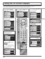
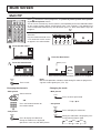
Using the On Screen Displays
Many features available on this set can be accessed via the On Screen Display menu system.
Use the remote control as shown below to access and adjust features as desired.
CONTRAST
MENU
BRIGHTNESS
COLOUR
SHARPNESS
C. TEMP
PICTURE
DYNAMIC
STANDARD
3D-COMB
P-NR
AUTO
ON
VOLUME
BASS
BALANCE
HEADPHONE VOL.
SURROUND
MENU
TREBLE
SOUND
OFF
MUSIC
TELETEXT
FASTEXT
OFF TIMER
OFF
POWER SAVE
OFF
CHILD LOCK
OFF
CH COLOUR SET
SIDE PANEL
HIGH
TEXT SELECT
ENGLISH
SETUP MENU
LANGUAGE ENGLISH
OWNER ID
SETUP MENU
TUNING MENU
Press to display “PICTURE
menu” screen. (see page 27, 28)
Press to display “SOUND menu”
screen. (see page 29, 30)
Press to display “SETUP MENU”
screen. (see page 26)
Normal
Setup
Normalise
H-Pos
H-Size
V-Pos
V-Size
Clock Phase
Sync
H & V
During “PC” input signal
(see page 34)
TELETEXT
FASTEXT
OFF TIMER
OFF
CHILD LOCK
OFF
CH COLOUR SET
SETUP MENU
LANGUAGE ENGLISH
OWNER ID
SETUP MENU
VCR/GAME
OFF
COLOUR SYS
PAL
TEXT SELECT
ENGLISH
POWER SAVE
OFF
SIDE PANEL
HIGH
During TV mode
During AV mode
When the TV is receiving NTSC/
YUV (60Hz) signals:
CONTRAST
MENU
BRIGHTNESS
COLOUR
SHARPNESS
C. TEMP
NTSC-TINT/TINT
PICTURE
DYNAMIC
STANDARD
3D-COMB
P-NR
PICTURE
AUTO
ON

17
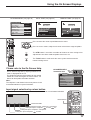
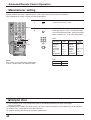
AUTO TUNE (see page 20) MANUAL TUNE (see page 21)
Using the On Screen Displays
Input selection will be made by colour button, which match on screen button indication.
Colour Bar Guide
AV1 AV2 AV3/PC
AV4
AV1
During AV4 input: Composite / Component
During AV3 input: Composite
S Video
PC
During AV2 input: Composite / Component
During AV1 input: Composite
S Video
Colour Buttons
Input signal selection by colour button
TV/AV
1 2 3
4 5 6
F. P.
INDEX HOLD
CH SEARCH
STILL
PICTURE
SOUND
SET UP
TV/TEXT
PC
SURROUND
To TUNING MENU (see page 18)
Press to move the cursor up and down on the menu.
Press to access menus, adjust levels or to select from a range of options.
The STR button is used with a number of features to store settings after
adjustments have been made or options have been set.
The TV/AV button is used to exit the menu system and return to the
normal viewing screen.
STR
TV/AV
FINE TUNE
COLOUR SYS
CH SELECT
SYS SELECT
AUTO TUNE
MANUAL TUNE
SOUND SYS
TUNING MENU
AUTO
SKIP
POSITION
ASIA/M.EAST
5. 5 MHz
OFF
CH 29
29
SETUP : RETURN TO TUNING MENU
TV/AV
: TO EXIT
AUTO SETUP IN PROGRESS
SEARCHING
: PLEASE WAIT
STORED CH29
CH 12
29
MANUAL TUNE
PROGRAMME
-
/+
SEARCH
-
/+
RETURN
TV
/
AV
-
EXIT
‘STR’ BUTTON-STORE
An On Screen Help box is displayed whenever a
menu is displayed on the TV.
This Help box indicates which buttons on the remote
control are used to navigate the menu shown, see
above for descriptions of button functions.
ON SCREEN HELP
‘Instruction’ box
Please refer to the On Screen Help
N
1 2 3
4 5 6
7 8 9
0
Note:
The Help box is not shown in the menu pictures in this
instruction book due to space limitations.
TV/AV
EXIT
SELECT
CHANGE
VOLUME
BASS
BALANCE
HEADPHONE VOL.
SURROUND
MENU
TREBLE
SOUND
OFF
MUSIC

18
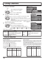
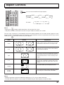
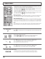
Press to select the “CH SELECT (Channel Select) ” Mode.
Press to select the “POSITION” or the “DIRECT”.
Setting range when the “POSITION” has been selected:
Position 0-99
Setting range when the “DIRECT” has been selected: Channel 0-125
CH SELECT
2
The channel select indicator will change as follows. DIRECT POSITION
Press to select the “SYS SELECT”.
Press to select the appropriate system.
The system select indicator will change as follows.
System Select by Regional
Select the most easily viewed channel selection method.
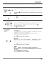
DIRECT SELECT
When the Channel Selection is on DIRECT, and AUTO TUNE
is performed, the unit memories the programme number which
is the same as the channel tuned.
This method allows you to select the desired channel by
pushing the channel display number directly on the remote
control to select the station. The channel display numbers for
the broadcast stations in each region are listed on page 19.
POSITION SELECT
When the Channel Selection is on POSITION, and AUTO
TUNE is performed, the unit memories the channels
tuned in order from programme No.1.
Press the button to view channel 2.
Press the button to view channel 4.
Press the button to view channel 6.
During position mode various reception channels can
be viewed.
CHINA HK/UK
ASIA/M.EAST
NZ/INDONES
AUSTRALIA
JAPAN CATV AMERICA
SPECL VER
E.EUROPE
SYSTEM SELECT
Region
CHINA
HK / UK
ASIA/M.EAST
NZ / INDONES
AUSTRALIA
China
Hong Kong, United Kingdom
Malaysia, Singapore, Thailand, Asia countries,
Kuwait, Saudi Arabia, United Arab Emirates,
Middle East countries, etc.
New Zealand, Indonesia, etc.
Australia
SYSTEM SELECT
Region
E.EUROPE
SPECL VER
AMERICA
CATV
JAPAN
CIS, Poland, etc.
South Africa
U.S.A., Chile, Mexico, Panama, Peru,
Philippines, Taiwan, Venezuela, etc.
USA CATV
Japan
Channel Selection
1
2
3
Example
Programme
Number
Channel
Display
Received
Channel
1
2
3
4
5
6
7
8
9
10
2
4
6
8
10
12
14
16
18
20
2
4
6
8
10
12
14
16
18
20
Example
Programme
Number
Channel
Display
Received
Channel
1
2
3
4
5
6
7
8
9
10
20
–
2
–
4
–
6
–
8
–
10
20
–
2
–
4
–
6
–
8
–
10
20
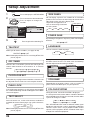
Regional System Selection
Select the “POSITION” or the “DIRECT”
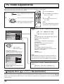
1
Display the TUNING MENU
Press to display the SETUP MENU.
Press to select the TUNING
MENU.
Press to access TUNING MENU.
Tuning Channels
SET UP
TELETEXT
FASTEXT
OFF TIMER
OFF
POWER SAVE
OFF
CHILD LOCK
OFF
CH COLOUR SET
SIDE PANEL
HIGH
TEXT SELECT
ENGLISH
SETUP MENU
FINE TUNE
COLOUR SYS
CH SELECT
SYS SELECT
AUTO TUNE
MANUAL TUNE
SOUND SYS
TUNING MENU
ASIA/M.EAST
5. 5 MHz
AUTO
SKIP
OFF
POSITION
FINE TUNE
COLOUR SYS
CH SELECT
SYS SELECT
AUTO TUNE
MANUAL TUNE
SOUND SYS
TUNING MENU
5. 5 MHz
AUTO
SKIP
OFF
POSITION
ASIA/M.EAST
3
LANGUAGE ENGLISH
OWNER ID
SETUP MENU
TUNING MENU
ACCESS

19
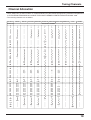
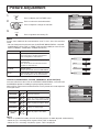
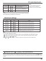
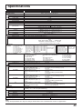
Tuning Channels
Channel Allocation
SYS SELECT
CH DISPLAY
CHINA HK/UK
ASIA/M.EAST
NZ/INDONES
AUSTRALIA
E.EUROPE
SPECL VER
AMERICA
CATV JAPAN
RECEIVE CHANNEL
0
1
2
3
4
5
6
7
11
12
13
14
15
16
19
20
–
1
2
12
13
–
–
–
–
–
–
–
–
–
–
–
–
–
–
–
–
–
–
–
–
2
11
12
–
–
–
–
–
–
–
–
1
2
11
–
–
–
–
–
–
–
–
–
0
1
2
3
4
5
S2
S10
6
9
9A
–
1
2
11
12
–
–
–
–
–
–
–
–
1
2
11
12
13
–
–
–
–
–
–
–
2
13
14
–
1
2
–
1
2
12
13
57
–
–
–
–
–
–
–
21
62
63
69
21
62
63
69
21
62
63
69
21
62
63
69
21
62
63
69
62
63
69
62
63
62
C13
–
–
–
–
–
–
–
–
–
–
–
–
S'1
S'2
S'3
–
–
–
–
–
–
S'1
S'2
S'3
–
–
–
–
–
–
S'1
S'2
S'3
–
–
–
–
–
–
S'1
–
–
–
–
–
–
–
–
S'1
S'2
S'3
–
–
–
–
–
–
–
–
–
–
–
–
21
22
23
24
28
57
58
59
62
63
69
90
91
92
93
94
95
96
97
98
99
70
73
74
75
76
77
78
79
80
81
89
100
107
117
118
120
125
–
–
–
–
–
–
–
–
–
–
100
125
Z10
Z11
Z12
Z13
Z14
Z15
Z16
Z17
Z18
Z19
S11
S12
S13
S14
S15
S16
S17
S18
S19
S20
S11
S12
S13
S14
S15
S16
S17
S18
S19
S20
S11
S12
S13
S14
S15
S16
S17
S18
S19
S20
S11
S12
S13
S14
S15
S16
S17
S18
S19
S20
–
–
–
S14
S15
S16
S17
S18
S19
S20
–
–
–
–
–
–
–
–
–
–
99 C49
10
11
12
S11
S44
20
21
–
Z1
Z9
S1
S2
S10
S1
S2
S10
S1
S2
S10
S1
S2
S10
S1
S2
S10
–
–
–
–
Z20
Z37
–
–
–
–
–
S21
S41
–
–
S21
S41
–
–
S21
S41
–
–
S21
S41
–
–
S21
S41
–
–
–
–
–
–
–
–
–
–
–
–
69
–
–
–
–
–
–
–
• CATV (USA CATV) channel numbers as recommended by the joint EIA/NCTA Engineering committee and published
as EIA INTERIM STANDARD No.6-CABLE TELEVISION CHANNEL IDENTIFICATION PLAN-MAY 1983.
• The receiving channels are as follows;

20
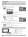
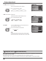
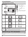
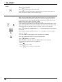
Tuning Channels
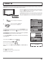
Auto Tune
This TV uses automatic tuning to determine whether or not the TV can receive a broadcast signal which is being sent,
and automatically prepares so that the channel selection can respond to both the position select and direct select
modes.
Before Automatic Tune, Channel Select and Regional System must already be set (see page 18).
The best tuning position is automatically
memorized.
AUTO TUNE
Press to select the “AUTO TUNE”.
Press to access to the “AUTO TUNE”.
Search Start.
1
When a station is found.
SOUND SYS
After all stations are tuned, the on-screen display will automatically change from “AUTO
TUNE” to “SOUND SYS” Position.
Note:
When the sound volume is too small to confirm, turn it up by using the sound volume button on the remote control.
It is not available when a menu is displayed.
2
Press to improve the Sound quality, if the Sound is not clear
or no sound is produced on a programme Number Position.
Press to exit from the TUNING MENU.
This returns the set to the normal viewing condition.
Press to store the Sound System.
3
Under the normal viewing condition press to enter each programme Number.
Confirm the tuning condition.
If necessary, repeat step 2 for each Programme Number.
STR
TV/AV
CH 29
29
SETUP : RETURN TO TUNING MENU
TV/AV
: TO EXIT
AUTO SETUP IN PROGRESS
SEARCHING
: PLEASE WAIT
STORED CH29
4.5MHz
6.5MHz
5.5MHz
6.0MHz
FINE TUNE
COLOUR SYS
CH SELECT
SYS SELECT
AUTO TUNE
MANUAL TUNE
SOUND SYS
TUNING MENU
ASIA/M.EAST
5. 5 MHz
AUTO
SKIP
OFF
POSITION
ACCESS
FINE TUNE
COLOUR SYS
CH SELECT
SYS SELECT
AUTO TUNE
MANUAL TUNE
SOUND SYS
TUNING MENU
5. 5 MHz
AUTO
SKIP
OFF
POSITION
ASIA/M.EAST
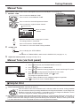
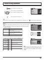
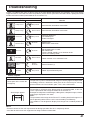
Auto Tune (via front panel)
It is also possible to use the control panel buttons on the front of the TV to tune individual programme positions.
S VIDEO
R - STANDBY
G - POWER ON
STR F TV/AV
AV3
VIDEO L R/ /
STR F TV/AV/ /
1 Press
F
(Front panel) until TUNING MODE is reached.
2 Press
/
or
/
to access TUNING MODE.
3 Press
F
(Front panel) to access AUTO TUNE.
4 Press
/
or
/
to start search.
Press
F
at any time to exit the TUNING MENU.
Page is loading ...
Page is loading ...
Page is loading ...
Page is loading ...
Page is loading ...
Page is loading ...
Page is loading ...
Page is loading ...
Page is loading ...
Page is loading ...
Page is loading ...
Page is loading ...
Page is loading ...
Page is loading ...
Page is loading ...
Page is loading ...
Page is loading ...
Page is loading ...
Page is loading ...
Page is loading ...
Page is loading ...
Page is loading ...
Page is loading ...
Page is loading ...
-
 1
1
-
 2
2
-
 3
3
-
 4
4
-
 5
5
-
 6
6
-
 7
7
-
 8
8
-
 9
9
-
 10
10
-
 11
11
-
 12
12
-
 13
13
-
 14
14
-
 15
15
-
 16
16
-
 17
17
-
 18
18
-
 19
19
-
 20
20
-
 21
21
-
 22
22
-
 23
23
-
 24
24
-
 25
25
-
 26
26
-
 27
27
-
 28
28
-
 29
29
-
 30
30
-
 31
31
-
 32
32
-
 33
33
-
 34
34
-
 35
35
-
 36
36
-
 37
37
-
 38
38
-
 39
39
-
 40
40
-
 41
41
-
 42
42
-
 43
43
-
 44
44


Panasonic TH42PA20M Owner's manual
- Category
- LCD TVs
- Type
- Owner's manual
- This manual is also suitable for
Ask a question and I''ll find the answer in the document
Finding information in a document is now easier with AI
Related papers
-
Panasonic TH-42PA50A User manual
-
-
Panasonic TX-26LX1M User manual
-
-
-
-
-
Panasonic TX20LA2X User manual
-
-
Panasonic KX-TG1613BL User manual