Page is loading ...

Read All Instructions Carefully Before Beginning Installation.
The BrassCraft® dual outlet valve allows two independent
connectors to be attached to a single valve. There is no need to
install a separate valve to run water to a separate appliance. The
result is one less installation which means less time on the job.
Unlike a standard dual outlet valve, the BrassCraft® dual outlet/dual
shut-off valve allows you to turn off the water to one source while
working on another. For instance, you can still run hot water out of
your faucet, but turn off the water supply to your dishwasher and not
require two separate valves to do it. Saves you installation time and
money. Dual outlets are great for:
• Dishwashers
• Ice Makers
• Water Filters
• Instant Hot Water Dispensers
INSTALLATION INSTRUCTIONS
CAUTION: FOR USE WITH WATER IN ACCESSIBLE LOCATIONS ONLY.
CAUTION: DO NOT SWEAT WITHIN 12 INCHES OF A DUAL OUTLET SHUT-OFF
VALVE.
CAUTION: DO NOT USE DUAL OUTLET SHUT-OFF VALVE OR MULTI-TURN
VALVES ON RECIRCULATION SYSTEMS EXCEEDING 115˚ F.
CAUTION: DO NOT USE WITH CONNECTORS HAVING A
SOLID BRASS CONE
OR BULL NOSE DESIGN - FRACTURES CAN DEVELOP.
CAUTION:
VALVE MUST BE USED IN THE FULLY OPENED OR FULLY CLOSED POSITION.
CAUTION: OUTLET MUST BE CAPPED IF VALVE IS BEING USED AS A
TERMINATION POINT.
Manufacturer assumes no responsibility for failure due to improper installation.
• For use with type L or M copper only.
• Be sure stub out and riser are square, round and free of burrs.
• Overtightening can cause product to crack and fail over time.
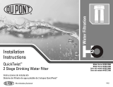
Dual Outlet and Dual Outlet/Dual Shut-Off Valves
Compression Inlet
INSTALLATION INSTRUCTIONS (CONTINUED)
Be sure to shut off main water supply before starting.
1. Open a faucet at the lowest point in the dwelling. This could be a basement
laundry tub faucet or outdoor garden spigot. This drains the water from the
system and reduces the amount of water that escapes when the existing valve is
removed.
2. Clean and debur the end of the copper tube using your deburring tool. Be sure to
remove any burrs, residue or sharp edges from the copper tube end.
3. Slide the compression nut and sleeve onto the copper pipe with the threads of the
nut facing you. Push both away from the tube end.
4. Slide the valve inlet onto the copper tube until you feel resistance. Be sure to
position the outlets of the valve to the desired directions for easy connection to
the faucet and appliance.
5. Place a small amount of oil or thread sealant only on the threads of the valve.
This makes it easier to tighten the compression nut. DO NOT USE a putty, gasket
material or thread seal tape. Hand tighten the nut.
6. Using hand tools, tighten 3/4 turn from the hand tight position. Note: Make sure
that the stop remains seated and square to the copper tube. If the stop is not
square to the copper tube, this could affect the ability to get a good connection.
7. Connect appropriate supply line to faucet and appliance according to the
manufacturer’s instructions.
8. Connect supply lines to the valve. Hand tighten. Then, using one wrench to
stabilize the valve and the other to tighten the connection, wrench tighten one and
a half turns.
9. Make sure handle is in the off position by rotating the handle clockwise until you
feel resistance.
10. Turn the main water supply back on and then open the valve.
11. If connecting to a faucet, remove the faucet aerator and turn on the faucet to
purge air from the line and wash through any contaminants.
12. Once the water runs smoothly, turn the faucet off and check the valve and supply
line for leaks. If a leak is present, slightly tighten the appropriate nut. Remember
to reattach the faucet aerator. Once that’s done, the installation is complete.
Tools Needed for Installation:
• Pail & rag • Two 10-inch adjustable wrenches
• Tube Cutter • Oil or thread sealant
• Deburring tool • Two new exible water connectors
Manufacturer assumes no responsibility for failure due to improper installation.
©2016 BrassCraft Mfg., Novi, MI 48375-5331 U.S.A. All Rights Reserved. www.brasscraft.com
El fabricante no asume ninguna responsabilidad si la instalación no se hace de acuerdo al instructivo.
425.11 02/16
www.brasscraft.com
TUBE / Tubo
COMPRESSION NUT
Tuerca de compresión
SLEEVE
Manga
VALVE INLET
Intrada de la
llave de paso
VALVE OUTLET
Salidas de la
llave de paso
VALVE OUTLET
Salidas de la
llave de paso

Llave de Paso de Doble Salida y llave de Paso de Doble Apagar
Entrada de Compresión
Lea todas las instrucciones atentamente antes de comenzar la
Instalación.
La válvula de salida dual BrassCraft
®
permite jar dos conectores
independientes a una sola válvula. No hay necesidad de instalar
una válvula adicional para suministrar agua a un electrodoméstico
distinto. El resultado es una instalación menos, lo que signica
menos tiempo en el trabajo.
A diferencia de una válvula de salida dual estándar, la válvula de
cierre dual/salida dual BrassCraft
®
le permite cortar el suministro de
agua a una fuente mientras trabaja en otra. Por ejemplo, puede dejar
correr agua caliente en su grifo, aún después de cortar el suministro
de agua a lavavajillas, y no necesitará de dos válvulas separadas
para hacerlo. Le ahorra dinero y tiempo de instalación. Las salidas
duales son excelentes para:
• Lavavajillas
• Fabricantes de hielo
• Filtros de agua
• Dispensadores de agua caliente instantánea
INSTRUCCIONES DE INSTALACIONES
PRECAUCIÓN: PARA USAR CON AGUA EN UBICACIONES ACCESIBLES SOLAMENTE.
PRECAUCIÓN: NO SOLDAR A MENOS DE 12 PULGADAS DE UNA VÁLVULA DUAL OUT
-
LET SHUT-OFF DE 1/4 DE VUELTA.
PRECAUCIÓN: NO USAR LLAVES DE PASO DUAL OUTLET SHUT-OFF NI VÁLVULAS
MULTIVUELTA EN SISTEMAS DE RECIRCULACIÓN QUE EXCEDAN 115˚ F.
PRECAUCIÓN: NO USAR CON CONECTORES QUE TENGAN UN CONO DE LATÓN SÓLIDO
O UN DISEÑO DE TAPÓN DE CABEZA REDONDA - PUEDEN PRODUCIRSE FRACTURAS.
PRECAUCIÓN: LA VÁLVULA DEBE USARSE EN LA POSICIÓN TOTALMENTE ABIERTA O
TOTALMENTE CERRADA.
PRECAUCIÓN: LA SALIDA DEBE ESTAR TAPADA SI LA VÁLVULA SE USA COMO PUNTO
DE TERMINACIÓN.
El fabricante no asume responsabilidad por fallas ocasionadas por una
instalación inadecuada.
• Para su uso con el tipo L o M sólo se cobre.
• Asegúrese talón y el tubo de subida son cuadradas, redondas, y sin rebabas.
• Apriete excesivo puede hacer que el producto se agriete y fallar con el tiempo. Ver
instrucciones más detalladas a continuación.
INSTRUCCIONES DE INSTALACIÓN (CONTINUACIÓN)
Asegúrese que el suministro de agua esté cerrado antes de inciar la
instalación.
1. Abre un grifo en el punto más bajo de la vivienda. Esto podría ser un grifo sótano
lavaderoo grifo jardín al aire libre. Esto drena el agua del sistema y reduce la
cantidad de agua que se escapa cuando se retira la válvula existente.
2. Limpio y quite las rebabas del extremo del tubo de cobre usando su herremienta
de desbarbado. Asegúrese de quitar las rebabas, residuos, o bordes alados del
extremo del tubo de cobre.
3. Deslice la tuerca de compresión y el manguito sobre el tubo de cobre con las
roscas de la tuerca frente a usted. Empuja tanto lejos del extremo del tubo.
4. Deslice la entrada de la válvula en el tubo de cobre hasta que sienta resistencia.
Asegúrese d colocar las salidas de válvula a las direcciones deseadas para una
fácil conexión al grifo y aparato.
5. Coloca una pequeña cantidad de aceite o sellador de roscas sólo en las roscas
de la válvula. Esto hace que sea más fácil para apretar la tuerca de compresión.
No utilice una cinta de masilla material de la junta, o cinta de sellado de rosca.
Apriete a mano la tuerca.
6. Utilizando herramientas manuales, apriete 3/4 de vuelta de la posición de ajuste
manual. Nota: Compruebe que la llave de paso permanece asentada y a escuadra
con el tubo de cobre. Si la llave de paso no está a escuadra con el tubo de cobre,
esto podría afectar la capacidad de lograr una buena conexión.
7. Conecta la línea de alimentación adecuada al grifo y el aparato de acuerdo a las
instrucciones del fabricante.
8. Conecta las líneas de suministro a la válvula. Apriete a mano. Luego, utilizando
una llave para estabilizar la válvula y el otro para apretar la conexión. Apriete de
llave vueltas a uno y media.
9. Asegúrese de mango está en las posición de apagado girando el mango hacia la
derecha hasta que sienta resistencia.
10. Gire el suministro principal de agua de nuevo y abra la válvula.
11. Si se conecta a un grifo, retire el aireador del grifo y abre el grifo para purgar el
aire de la línea y lavar a través de contaminantes.
12. Una vez que el agua corre sin problemas, apaga el grifo y compruebe el
suministro y la válvula para que no haya fugas. Si hay una fuga, apriete
ligeramente la tuerca apropiada. Recorda para volver a colocar el aireador del
grifo. Una vez hecho esto, la instalación se ha completado.
Herramientas Necesarias:
• Balde y trapo • Dos (2) llaves ajustables de 10 pulgadas
• Cortador de tubo • Aceite o sellador de roscas
• Herramienta de desbarbado • Dos (2) nuevos conectores de agua
exibles
TUBE / Tubo
COMPRESSION NUT
Tuerca de compresión
SLEEVE
Manga
VALVE INLET
Intrada de la
llave de paso
VALVE OUTLET
Salidas de la
llave de paso
VALVE OUTLET
Salidas de la
llave de paso
Manufacturer assumes no responsibility for failure due to improper installation.
©2016 BrassCraft Mfg., Novi, MI 48375-5331 U.S.A. All Rights Reserved. www.brasscraft.com
El fabricante no asume ninguna responsabilidad si la instalación no se hace de acuerdo al instructivo.
425.11 02/16
www.brasscraft.com
/