
MFC Series Boilers User Manual
OMM-0104_94 AERCO International, Inc. • 100 Oritani Dr. • Blauvelt, NY 10913 Page 1 of 170
GF-146 Ph.: 800-526-0288 12/29/2015
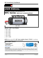
USER MANUAL
Installation, Operation and Maintenance of:
MFC Series Multi-Fuel Condensing Boilers
MFC 10000
Applies to MFC Series Models:
• MFC 3000
• MFC 4000
• MFC 5000
• MFC 6000
• MFC 8000
• MFC 10000
NOTE: Refer to the AERCO MFC Series Installation Manual, GF-146-IN, for preliminary
assembly and installation instructions and information.
Latest Update: 12/29/2015

MFC Series Boilers User Manual
CONTENTS
Page 2 of 170 AERCO International, Inc. • 100 Oritani Dr. • Blauvelt, NY 10913 OMM-0104_94
12/29/2015 Ph.: 800-526-0288 GF-146
TABLE OF CONTENTS
FOREWORD .......................................................................................................................................... 7
SECTION 1: SAFETY PRECAUTIONS .................................................................................. 8
1.1 Warnings & Cautions ........................................................................................................................... 8
1.2 Emergency Shutdown.......................................................................................................................... 9
1.3 Prolonged Shutdown ........................................................................................................................... 9
1.4 Massachusetts Installations .............................................................................................................. 10
SECTION 2: INTRODUCTION ...............................................................................................12
2.1 General Features ............................................................................................................................... 12
2.2 Certification References and Compliance ......................................................................................... 12
2.3 General Technical Specifications ....................................................................................................... 13
SECTION 3: INSTALLATION ................................................................................................15
3.1 Receiving The Unit ............................................................................................................................. 15
3.2 Moving & Unpacking the Unit ........................................................................................................... 15
3.3 Site Preparation ................................................................................................................................. 18
Electrical Requirements .............................................................................................................. 18 3.3.1
Natural Gas Requirements ......................................................................................................... 18 3.3.2
Installation Clearances ................................................................................................................ 19 3.3.3
3.4 Installation - Site ................................................................................................................................ 20
3.5 Boiler Room ....................................................................................................................................... 20
3.6 Flue .................................................................................................................................................... 21
3.7 Water Connections ............................................................................................................................ 21
3.8 Sealed Hot Water Heating System w/ Expansion Vessel .................................................................. 21
3.9 Electrical Connections ....................................................................................................................... 22
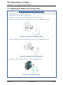
3.10 Burner Door Opening Orientation ................................................................................................... 23
3.11 Reversing the Opening Direction of the Burner Door ..................................................................... 23
3.12 Adjusting the Boiler Door – Vertical and Horizontal ....................................................................... 26
SECTION 4: STARTUP .........................................................................................................28
4.1 Preliminary Checks ............................................................................................................................ 28
4.2 Water Treatment ............................................................................................................................... 28
Scaling ......................................................................................................................................... 28 4.2.1
Corrosion on the Water Side ...................................................................................................... 28 4.2.2
4.3 Filling the System............................................................................................................................... 29
SECTION 5: BURNER INSTALLATION ................................................................................30
5.1 Burner Pre-Installation Procedures ................................................................................................... 30
5.2 Burner Installation ............................................................................................................................. 30
SECTION 6: MFC 3000 DUAL FUEL BURNER.....................................................................31
6.1 MFC 3000 Dual Fuel Burner Features ................................................................................................ 32
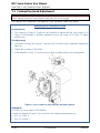
6.2 Burner Nozzle Setup .......................................................................................................................... 34
Recommended Nozzles .............................................................................................................. 34 6.2.1
Nozzle Assembly ......................................................................................................................... 34 6.2.2
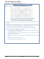
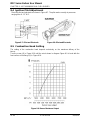
6.3 Flow Rate adjustment ....................................................................................................................... 35
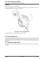
6.4 Electrode Positioning ......................................................................................................................... 36
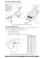
6.5 Burner Setup...................................................................................................................................... 37
6.6 Hydraulic Connections ....................................................................................................................... 38
6.7 Pump ................................................................................................................................................. 39

MFC Series Boilers User Manual
CONTENTS
OMM-0104_94 AERCO International, Inc. • 100 Oritani Dr. • Blauvelt, NY 10913 Page 3 of 170
GF-146 Ph.: 800-526-0288 12/29/2015
Pump Priming ............................................................................................................................. 39 6.7.1
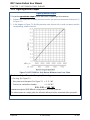
6.8 Gas Pressure ...................................................................................................................................... 40
6.9 Combustion Head Adjustment .......................................................................................................... 42
6.10 Pump Adjustment ............................................................................................................................ 43
6.11 Air Damper Adjustment ................................................................................................................... 43
6.12 Ignition Pilot Adjustment ................................................................................................................. 43
6.13 Adjustments before First Firing (Gas Operation) ............................................................................ 44
6.14 Startup for MFC 3000 Dual Fuel Burner ......................................................................................... 46
Gas/Air Delivery Adjustment .................................................................................................... 47 6.14.1
Adjusting Oil/Air Delivery .......................................................................................................... 47 6.14.2
Air Pressure Switch Adjustment................................................................................................ 48 6.14.3
Maximum Gas Pressure Switch Adjustment ............................................................................. 49 6.14.4
Minimum Gas Pressure Switch Adjustment .............................................................................. 49 6.14.5
Low Oil Pressure Switch ............................................................................................................ 50 6.14.6
High oil pressure switch ............................................................................................................ 50 6.14.7
Burner Startup Sequence of Operation .................................................................................... 51 6.14.8
Normal Operation Sequence of Operation ............................................................................... 52 6.14.9
6.15 Final Checks with Boiler in Operation ............................................................................................. 53
SECTION 7: MFC 3000 NATURAL GAS ONLY BURNER ....................................................54
7.1 Combustion Head Adjustment .......................................................................................................... 57
7.2 Gas Supply Pressure .......................................................................................................................... 59
Figuring Burner Output ............................................................................................................... 60 7.2.1
Figuring Required Burner Output ............................................................................................... 61 7.2.2
7.3 Adjustments Before First Firing (Gas) ............................................................................................... 62
7.4 Startup for MFC 3000 Gas Only Burner ............................................................................................ 64
Gas/Air Delivery Adjustment ...................................................................................................... 65
7.4.1
Air Pressure Switch Adjustment.................................................................................................. 66 7.4.2
Maximum Gas Pressure Switch Adjustment ............................................................................... 67 7.4.3
Minimum Gas Pressure Switch Adjustment ................................................................................ 67 7.4.4
7.5 Final Checks with Boiler in Operation ............................................................................................... 68
SECTION 8: MFC 4000 / 6000 DUAL FUEL BURNER ..........................................................69
8.1 MFC 4000-6000 Dual Fuel Burner Features ...................................................................................... 70
8.2 Burner Nozzle Setup .......................................................................................................................... 72
Recommended Nozzles .............................................................................................................. 72 8.2.1
Nozzle Assembly ......................................................................................................................... 72 8.2.2
8.3 Flow Rate Adjustment ....................................................................................................................... 73
8.4 Ignition Pilot Adjustment ................................................................................................................... 75
8.5 Combustion Head Setting .................................................................................................................. 75
8.6 Pump Adjustment .............................................................................................................................. 76
8.7 Air Damper Adjustment..................................................................................................................... 76
8.8 Electrode Positioning ......................................................................................................................... 77
8.9 Burner Setup...................................................................................................................................... 78
8.10 Hydraulic Connections ..................................................................................................................... 79
8.11 Pump ............................................................................................................................................... 80
Pump Priming ........................................................................................................................... 80 8.11.1
8.12 Gas Pressure .................................................................................................................................... 81
8.13 Burner Firing .................................................................................................................................... 82
8.14 Burner Calibration ........................................................................................................................... 83
8.15 Adjustments Before First Firing (Gas Operation) ............................................................................ 83

MFC Series Boilers User Manual
CONTENTS
Page 4 of 170 AERCO International, Inc. • 100 Oritani Dr. • Blauvelt, NY 10913 OMM-0104_94
12/29/2015 Ph.: 800-526-0288 GF-146
Startup for MFC 4000 – 6000 Dual Fuel Burner ....................................................................... 85 8.15.1
Gas/Air Delivery Adjustment .................................................................................................... 86 8.15.2
Adjusting Oil/Air Delivery .......................................................................................................... 86 8.15.3
Air Pressure Switch Adjustment................................................................................................ 87 8.15.4
Maximum Gas Pressure Switch Adjustment ............................................................................. 88 8.15.5
Minimum Gas Pressure Switch Adjustment .............................................................................. 88 8.15.6
Low Oil Pressure Switch ............................................................................................................ 89 8.15.7
High oil pressure switch ............................................................................................................ 89 8.15.8
Burner Startup Sequence of Operation .................................................................................... 90 8.15.9
Normal Operation Sequence of Operation ............................................................................. 91 8.15.10
8.16 Firing Failure .................................................................................................................................... 92
8.17 Final Checks with Boiler in Operation ............................................................................................. 92
SECTION 9: MFC 4000-6000 GAS ONLY BURNER .............................................................93
9.1 Combustion Head Adjustment .......................................................................................................... 93
9.2 Gas Supply Pressure .......................................................................................................................... 95
Figuring Burner Output ............................................................................................................... 95 9.2.1
9.3 Adjustments Before First Firing ......................................................................................................... 96
9.4 Startup for MFC 4000-6000 Gas Only Burner ................................................................................... 98
Combustion Air Adjustment ....................................................................................................... 99 9.4.1
Gas/Air Delivery Adjustment ...................................................................................................... 99 9.4.2
Air/Fuel Control and Power Modulation System ..................................................................... 100 9.4.3
9.5 Final Calibration of the Pressure Switches ...................................................................................... 101
Air Pressure Switch Adjustment................................................................................................ 101 9.5.1
Maximum Gas Pressure Switch Adjustment ............................................................................. 102 9.5.2
Minimum Gas Pressure Switch Adjustment .............................................................................. 102
9.5.3
9.6 Final Checks with Boiler in Operation ............................................................................................. 103
SECTION 10: MFC 8000 / 10000 DUAL FUEL BURNER ...................................................... 104
10.1 MFC 8000-10000 Dual Fuel Burner Features ................................................................................ 105
10.2 Burner Nozzle Setup ...................................................................................................................... 107
Recommended Nozzles .......................................................................................................... 107 10.2.1
Nozzle Assembly ..................................................................................................................... 107 10.2.2
10.3 Combustion Head setting .............................................................................................................. 108
10.4 Hydraulic Connections ................................................................................................................... 110
10.5 Pressure Variator ........................................................................................................................... 111
10.6 Pump ............................................................................................................................................. 112
Pump Priming ......................................................................................................................... 112 10.6.1
10.7 Gas Train ........................................................................................................................................ 113
10.8 Gas Pressure .................................................................................................................................. 113
10.9 Adjustments before First Firing (Light Oil Operation) ................................................................... 114
10.10 Nozzles ......................................................................................................................................... 114
10.11 Combustion Head ........................................................................................................................ 114
10.12 Pump Pressure ............................................................................................................................ 115
10.13 Burner Firing ................................................................................................................................ 115
10.14 Changing Fuel Type ..................................................................................................................... 115
10.15 Adjustments before First Firing (Gas Operation) ........................................................................ 116
10.16 Burner Start-Up ........................................................................................................................... 117
Combustion Air Adjustment ................................................................................................. 118 10.16.1
Air Adjustment for Maximum Output .................................................................................. 118 10.16.2
Gas/Air Delivery Adjustment ................................................................................................ 118 10.16.3

MFC Series Boilers User Manual
CONTENTS
OMM-0104_94 AERCO International, Inc. • 100 Oritani Dr. • Blauvelt, NY 10913 Page 5 of 170
GF-146 Ph.: 800-526-0288 12/29/2015
Adjusting Oil/Air Delivery ...................................................................................................... 119 10.16.4
Air/Fuel Control and Power Modulation System ................................................................. 119 10.16.5
10.17 Final Calibration of the Pressure Switches .................................................................................. 120
Air Pressure Switch Adjustment............................................................................................ 120 10.17.1
Maximum Gas Pressure Switch Adjustment ......................................................................... 121 10.17.2
Minimum Gas Pressure Switch Adjustment .......................................................................... 121 10.17.3
Low Oil Pressure Switch ........................................................................................................ 122 10.17.4
Burner Startup Sequence of Operation ................................................................................ 123 10.17.5
Normal Operation Sequence of Operation ........................................................................... 124 10.17.6
10.18 Firing Failure ................................................................................................................................ 124
10.19 Final Checks with Boiler in Operation ......................................................................................... 124
SECTION 11: MFC 8000-10000 GAS ONLY BURNER ......................................................... 125
11.1 MFC 8000-10000 Gas Only Burner Features ................................................................................. 125
11.2 Combustion Head Adjustment ...................................................................................................... 126
11.3 Rotation of the Fan Motor ............................................................................................................ 128
11.4 Gas Train ........................................................................................................................................ 128
11.5 Gas Pressure .................................................................................................................................. 129
11.6 Adjustments before First Firing ..................................................................................................... 130
11.7 Startup for MFC 8000-10000 Gas Only Burner ............................................................................. 132
Burner Firing ........................................................................................................................... 133 11.7.1
Combustion Air Adjustment ................................................................................................... 133 11.7.2
Gas/Air Delivery Adjustment .................................................................................................. 133 11.7.3
Air/Fuel Control and Power Modulation System.................................................................... 134 11.7.4
11.8 Final Calibration of the Pressure Switches .................................................................................... 135
Air Pressure Switch Adjustment.............................................................................................. 135 11.8.1
Maximum Gas Pressure Switch Adjustment ........................................................................... 136
11.8.2
Minimum Gas Pressure Switch Adjustment ............................................................................ 136 11.8.3
11.9 Final Checks with Boiler in Operation ........................................................................................... 137
SECTION 12: FLAME SIGNAL MEASUREMENT ................................................................. 138
Final Checks with Boiler in Operation ..................................................................................... 138 12.1.1
SECTION 13: MFC SERIES MAINTENANCE ....................................................................... 139
13.1 Preparation for Inspection and Maintenance ............................................................................... 139
13.2 Standard Maintenance .................................................................................................................. 140
13.3 Burner Maintenance ..................................................................................................................... 141
13.4 RS-120 / RS-160 Burner Maintenance (MFC 3000-6000) .............................................................. 141
Combustion ............................................................................................................................. 141 13.4.1
Gas Leaks ................................................................................................................................ 141 13.4.2
Flame inspection Window ...................................................................................................... 141 13.4.3
Combustion Head ................................................................................................................... 142 13.4.4
Nozzles (Fuel Oil) (Dual Fuel Models Only) ............................................................................. 142 13.4.5
Flexible Hoses (Fuel Oil) (Dual Fuel Models Only) .................................................................. 142 13.4.6
UV Scanner ............................................................................................................................. 142 13.4.7
Burner ..................................................................................................................................... 143 13.4.8
Combustion ............................................................................................................................. 143 13.4.9
13.5 RS-300 Burner Maintenance (MFC 8000-10000) .......................................................................... 143
Maintenance Frequency ......................................................................................................... 143 13.5.1
Combustion ............................................................................................................................. 143 13.5.2
Gas Leaks ................................................................................................................................ 143 13.5.3
Combustion Head ................................................................................................................... 143 13.5.4

MFC Series Boilers User Manual
CONTENTS
Page 6 of 170 AERCO International, Inc. • 100 Oritani Dr. • Blauvelt, NY 10913 OMM-0104_94
12/29/2015 Ph.: 800-526-0288 GF-146
Measurement of Detector Current ......................................................................................... 143 13.5.5
Fan .......................................................................................................................................... 144 13.5.6
Burner ..................................................................................................................................... 144 13.5.7
Boiler ....................................................................................................................................... 144 13.5.8
13.6 Light Oil Operation (MFC 8000-10000 Dual Fuel Only) ................................................................. 144
Pump ....................................................................................................................................... 144 13.6.1
Filters ...................................................................................................................................... 144 13.6.2
Nozzles .................................................................................................................................... 144 13.6.3
Flexible Hoses ......................................................................................................................... 144 13.6.4
Fuel Tank ................................................................................................................................. 144 13.6.5
Combustion ............................................................................................................................. 144 13.6.6
13.7 Gas Operation (MFC 8000-10000 Only) ........................................................................................ 144
Gas Leaks ................................................................................................................................ 144 13.7.1
Gas filter.................................................................................................................................. 145 13.7.2
Combustion ............................................................................................................................. 145 13.7.3
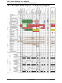
APPENDIX A – OPERATIONAL SEQUENCE DIAGRAMS ................................................... 146
13.8 MFC 3000-6000 Sequence of Operation Diagram ........................................................................ 146
13.9 MFC 8000-10000 Sequence of Operation Diagram ...................................................................... 147
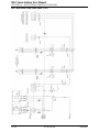
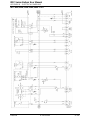
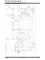
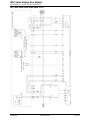
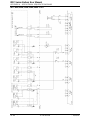
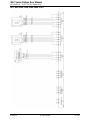
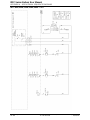
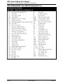
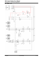
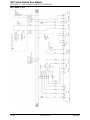
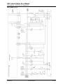
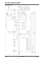
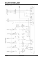
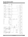
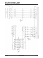
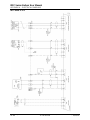
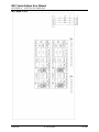
APPENDIX B – ELECTRICAL DIAGRAMS ........................................................................... 150
MFC 3000 / 4000 / 5000 / 6000 Electrical Diagrams 1-8 ...................................................................... 150
MFC 8000/10000 - ElectRICAL Diagrams 1-9 ........................................................................................ 159

MFC Series Boilers User Manual
FORWARD
OMM-0104_94 AERCO International, Inc. • 100 Oritani Dr. • Blauvelt, NY 10913 Page 7 of 170
GF-146 Ph.: 800-526-0288 12/29/2015
Foreword
The AERCO MFC Series boilers are modulating and condensing units. The MFC Series
represents a true industry advancement that meets the needs of today's energy and
environmental concerns. Designed for application in any closed loop hydronic system, the MFC
Series modulating capability relates energy input directly to fluctuating system loads. The
maximum turn down ratio for these units is 5:1. The MFC Series provides extremely high
efficiency and makes it ideally suited for modern low temperature, as well as, conventional
heating systems and higher temperature systems (up to 230°F).
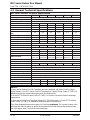
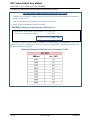
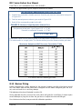
The MFC Series operates within the following input and output ranges:
MFC Series INPUT and OUTPUT RANGES (Btu/Hr.)
MODEL
INPUT RANGE (BTU/HR.)
OUTPUT RANGE (BTU/HR.) at High Fire Rate
*
Min. Max. Min. Max.
MFC 3000
600,000 3,000,000 2,565,000 2,850,000
MFC 4000
800,000 4,000,000 3,420,000 3,800,000
MFC 5000
1,000,000 5,000,000 4,275,000 4,750,000
MFC 6000
1,200,000 6,000,000 5,130,000 5,700,000
MFC 8000
1,600,000 8,000,000 6,840,000 7,600,000
MFC 10000
2,000,000 10,000,000 8,550,000 9,500,000
* Output based on a supply temperature based 80°F incoming water with a 20F° rise.
Whether used in singular or modular arrangements, the MFC Series offers the maximum
venting flexibility with minimum installation space requirements. These Boilers are Category II
and IV, positive pressure appliances. Single and/or multiple breeched units are capable of
operation in the following vent configurations:
• Room Combustion Air:
o Vertical Discharge
o Horizontal Discharge
• Ducted Combustion Air:
o Vertical Discharge
o Horizontal Discharge
These boilers are capable of being vented utilizing AL29-4C vent systems only.
The available burner’s advanced electronics are available with several selectable modes of
operation offering the most efficient operating methods and energy management system
integration.
IMPORTANT:
Unless otherwise specified, all descriptions and procedures provided in this Installation,
Operation & Maintenance Manual apply to the MFC Series boilers.

MFC Series Boilers User Manual
CHAPTER 1: SAFETY PRECAUTIONS
Page 8 of 170 AERCO International, Inc. • 100 Oritani Dr. • Blauvelt, NY 10913 OMM-0104_94
12/29/2015 Ph.: 800-526-0288 GF-146
SECTION 1: Safety Precautions
1.1 Warnings & Cautions
Installers and operating personnel MUST, at all times, observe all safety regulations. The
following warnings and cautions are general and must be given the same attention as specific
precautions included in these instructions. In addition to all the requirements included in this
AERCO Instruction Manual, the installation of units MUST conform with local building codes, or,
in the absence of local codes, ANSI Z223.1 (National Fuel Gas Code Publication No. NFPA-54)
for gas-fired boilers and ANSI/NFPASB for LP gas-fired boilers, as well as NFPA 31 “Standard
for the Installation of Oil-Burning Equipment”, and NFPA 54 for gas piping compliance
requirements. Where applicable, the equipment shall be installed in accordance with the current
Installation Code for Gas Burning Appliances and Equipment, CSA B149.1, and applicable
Provincial regulations for the class; which should be carefully followed in all cases. Authorities
having jurisdiction should be consulted before installations are made.
See pages 14 and 15 for important information regarding installation of units within the
Commonwealth of Massachusetts.
IMPORTANT:
This Instruction Manual is an integral part of the product and must be maintained in legible
condition. It must be given to the user by the installer and kept in a safe place for future
reference.
WARNING:
• Do not use matches, candles, flames, or other sources of ignition to check for gas leaks.
• Fluids under pressure may cause injury to personnel or damage to equipment when released.
Be sure to shut off all incoming and outgoing water shutoff valves. Carefully decrease all
trapped pressures to zero before performing any waterside maintenance or inspection.
• Before attempting to perform any maintenance on the unit, shut off all gas and electrical inputs
to the unit.
• The exhaust vent pipe of the unit may operate under a positive pressure and therefore must
be completely sealed to prevent leakage of combustion products into living spaces.
• Electrical voltages up to 575 VAC may be used in this equipment. Therefore the burner cover
and all other junction boxes must be installed at all times, except during maintenance and
servicing.
• A three-pole switch must be installed on the electrical supply line of the unit. The switch must
be installed in an easily accessible position to quickly and safely disconnect electrical service.
Do not affix switch to unit or burner enclosures.
CAUTION:
• Many kinds of soap used for gas pipe leak testing are corrosive to metals. The piping must
be rinsed thoroughly with clean water after leak checks have been completed.
• DO NOT use this boiler if any part has been under water. Call a qualified service technician
to inspect and replace any part that has been under water.

MFC Series Boilers User Manual
CHAPTER 1: SAFETY PRECAUTIONS
OMM-0104_94 AERCO International, Inc. • 100 Oritani Dr. • Blauvelt, NY 10913 Page 9 of 170
GF-146 Ph.: 800-526-0288 12/29/2015
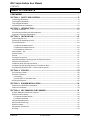
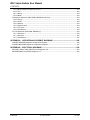
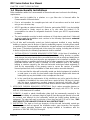
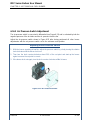
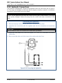
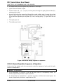
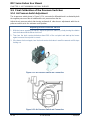
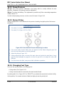
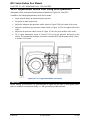
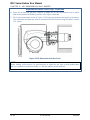
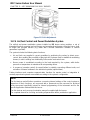
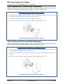
1.2 Emergency Shutdown
If overheating occurs or the gas supply fails to shut off, close the manual gas shutoff valve
(Figure 1-1) located external to the unit.
NOTE:
The Installer must identify and indicate the location of the emergency shutdown manual gas
valve to operating personnel.
Figure
1-1: Manual Gas Shutoff Valve
1.3 Prolonged Shutdown
If the boiler is to be taken out of service for an extended period of time (one year or more),
perform the following procedure.
Shutting Boiler Down for Extended Period
1. Set ON/OFF switch on the front panel to the OFF position to shut down the boiler’s
operating controls.
2. Disconnect AC power from the unit.
3. Close the water supply and return valves to isolate boiler.
4. Close external gas supply valve.
5. Open relief valve to vent water pressure.
To bring the boiler back into service after a prolonged shutdown (one year or more), the
following procedures must be followed:
Placing Boiler in Service After Long Shutdown
1. Review installation requirements included in Chapter 3.
2. Inspect all piping and connections to the unit.
3. Inspect exhaust vent and air inlet duct work (if applicable).
4. Perform initial startup per Chapter 5.
5. Perform scheduled maintenance procedures per Chapters 6 of this manual.

MFC Series Boilers User Manual
CHAPTER 1: SAFETY PRECAUTIONS
Page 10 of 170 AERCO International, Inc. • 100 Oritani Dr. • Blauvelt, NY 10913 OMM-0104_94
12/29/2015 Ph.: 800-526-0288 GF-146
1.4 Massachusetts Installations
Boiler installations within the Commonwealth of Massachusetts must conform to the following
requirements:
• Boiler must be installed by a plumber or a gas fitter who is licensed within the
Commonwealth of Massachusetts.
• Prior to unit operation, the complete gas train and all connections must be leak tested
using a non-corrosive soap.
• AERCO provides an optional external CO Detector, part number 58092. It can be installed
and conFigured to simply sound an alarm or to shut down the boiler(s) if CO
concentrations rise above a configurable threshold. Contact your AERCO representative
for details.
• The vent termination must be located a minimum of 4 feet above grade level. If side-wall
venting is used, the installation must conform to the following requirements extracted
from 248 CMR 5.08 (2):
(a) For all side wall horizontally vented gas fueled equipment installed in every dwelling,
building or structure used in whole or in part for residential purposes, including those owned
or operated by the Commonwealth and where the side wall exhaust vent termination is less
than seven (7) feet above finished grade in the area of the venting, including but not limited
to decks and porches, the following requirements shall be satisfied:
• INSTALLATION OF CARBON MONOXIDE DETECTORS. At the time of installation of
the side wall horizontal vented gas fueled equipment, the installing plumber or gasfitter
shall observe that a hard wired carbon monoxide detector with an alarm and battery back-
up is installed on the floor level where the gas equipment is to be installed. In addition, the
installing plumber or gasfitter shall observe that a battery operated or hard wired carbon
monoxide detector with an alarm is installed on each additional level of the dwelling,
building or structure served by the side wall horizontal vented gas fueled equipment. It
shall be the responsibility of the property owner to secure the services of qualified
licensed professionals for the installation of hard wired carbon monoxide detectors.
a. In the event that the side wall horizontally vented gas fueled equipment is installed in
a crawl space or an attic, the hard wired carbon monoxide detector with alarm and
battery back-up may be installed on the next adjacent floor level.
b. In the event that the requirements of this subdivision can not be met at the time of
completion of installation, the owner shall have a period of thirty (30) days to comply
with the above requirements; provided, however, that during said thirty (30) day
period, a battery operated carbon monoxide detector with an alarm shall be installed.
1. APPROVED CARBON MONOXIDE DETECTORS. Each carbon monoxide detector as
required in accordance with the above provisions shall comply with NFPA 720 and be
ANSI/UL 2034 listed and IAS certified.
2. SIGNAGE. A metal or plastic identification plate shall be permanently mounted to the
exterior of the building at a minimum height of eight (8) feet above grade directly in line with
the exhaust vent terminal for the horizontally vented gas fueled heating appliance or
equipment. The sign shall read, in print size no less than one-half (1/2) inch in size, "GAS
VENT DIRECTLY BELOW. KEEP CLEAR OF ALL OBSTRUCTIONS".
3. INSPECTION. The state or local gas inspector of the side wall horizontally vented gas
fueled equipment shall not approve the installation unless, upon inspection, the inspector
observes carbon monoxide detectors and signage installed in accordance with the
provisions of 248 CMR 5.08(2)(a)1 through 4.

MFC Series Boilers User Manual
CHAPTER 1: SAFETY PRECAUTIONS
OMM-0104_94 AERCO International, Inc. • 100 Oritani Dr. • Blauvelt, NY 10913 Page 11 of 170
GF-146 Ph.: 800-526-0288 12/29/2015
(b) EXEMPTIONS: The following equipment is exempt from 248 CMR 5.08(2)(a)1 through
4:
1. The equipment listed in Chapter 10 entitled "Equipment Not Required To Be Vented" in
the most current edition of NFPA 54 as adopted by the Board; and
2. Product Approved side wall horizontally vented gas fueled equipment installed in a room
or structure separate from the dwelling, building or structure used in whole or in part for
residential purposes.
(c) MANUFACTURER REQUIREMENTS - GAS EQUIPMENT VENTING SYSTEM PROVIDED.
When the manufacturer of Product Approved side wall horizontally vented gas equipment
provides a venting system design or venting system components with the equipment, the
instructions provided by the manufacturer for installation of the equipment and the venting
system shall include:
1. Detailed instructions for the installation of the venting system design or the venting
system components; and
2. A complete parts list for the venting system design or venting system.
(d) MANUFACTURER REQUIREMENTS - GAS EQUIPMENT VENTING SYSTEM NOT
PROVIDED. When the manufacturer of a Product Approved side wall horizontally vented
gas fueled equipment does not provide the parts for venting the flue gases, but identifies
"special venting systems", the following requirements shall be satisfied by the manufacturer:
1. The referenced "special venting system" instructions shall be included with the appliance
or equipment installation instructions; and
2. The "special venting systems" shall be Product Approved by the Board, and the
instructions for that system shall include a parts list and detailed installation instructions.
(e) A copy of all installation instructions for all Product Approved side wall horizontally vented
gas fueled equipment, all venting instructions, all parts lists for venting instructions, and/or
all venting design instructions shall remain with the appliance or equipment at the
completion of the installation.
____________________________________________________________________________
[End of Extracted Information From 248 CMR 5.08 (2)]

MFC Series Boilers User Manual
CHAPTER 2: INTRODUCTION
Page 12 of 170 AERCO International, Inc. • 100 Oritani Dr. • Blauvelt, NY 10913 OMM-0104_94
12/29/2015 Ph.: 800-526-0288 GF-146
SECTION 2: Introduction
2.1 General Features
The AERCO Multi-Fuel Condensing (MFC) Fire Tube Water Boiler is designed for condensing
application in any closed loop hydronic system. It features a proven 4-pass fire tube heat
exchanger design for maximum heat transfer and efficiency. The heat exchanger’s combination
of high quality carbon steel/316Ti stainless steel construction ensures the highest degree of
durability. The 316Ti SS construction in the heat exchanger’s 4th pass offers superior corrosion
resistance against acidic flue gas condensation. Likewise, it can be fired with multiple fuels
including natural gas, propane or #2 fuel oil (as backup), offering dual fuel flexibility. Moreover,
the MFC series features dual return connections standard for optimal application flexibility and
seasonal efficiency gains of up to 12%. The heat exchanger’s maximum working temperature of
240°F allows for greater operating temperature range and meet the requirements of higher
temperature applications when necessary, but allows for the building to reset water temperature
for condensing in the shoulder months.
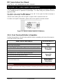
2.2 Certification References and Compliance
Each boiler and Stainless Steel 4th Pass is provided with a manufacture plate that can be
found in the envelope with the boiler documents. The plate lists:
Manufacturer Plate Information
BOILER
STAINLESS STEEL 4TH PASS
Serial Number
Serial Number
Minimum Relief Valve Capacity
Maximum Water Temperature
Heating Surface Area
Maximum Operating Pressure
Maximum Water Temperature
Maximum Operating Pressure
The installation must be performed in compliance with the regulations in force by
professionally qualified personnel. The term “professionally qualified personnel” means
persons with specific technical skills in the sector of heating system components. Incorrect
installation may cause damage to persons, animals or objects for which the manufacturer
cannot be held responsible.
At the first start up, all regulation and control devices positioned on the control panel should
be checked for proper operation.
The warranty shall be valid only upon compliance with the instruction given in this manual.
The AERCO MFC Series boilers have been built and tested in observance of ASME
requirements and UL (In Process), when ordered with a factory supplied burner.

MFC Series Boilers User Manual
CHAPTER 2: INTRODUCTION
OMM-0104_94 AERCO International, Inc. • 100 Oritani Dr. • Blauvelt, NY 10913 Page 13 of 170
GF-146 Ph.: 800-526-0288 12/29/2015
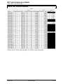
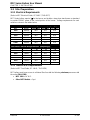
2.3 General Technical Specifications
MFC Series General Technical Specifications
MFC 3000
MFC 4000
MFC 5000
MFC 6000
MFC 8000
MFC 10000
Boiler Category
ASME Sect.IV
Max. Allowed Working Pressure
80 PSIG
Max. Working Temperature
240°F
Gas Connections (NPT)
2”
2”
2’’
2’’
3’’ (Flange)
3’’ (Flange)
Oil Connections
.375”
.375”
.5”
.5”
.5”
.5”
Max. Gas Pressure
2 psi
2 psi
2 psi
2 psi
5 psi
2 psi
Min. Gas Pressure
1
5”
5”
5”
5”
5”
5”
Max #2 Fuel Oil Consumption Flow
rate
(GPH)
21.4 28.6 35.7 42.9 57.1 71.4
#2 Fuel Oil Supply Flow Rate
85 150 150 150 218 218
Electrical Req. 208V/3PH/60Hz
2, 3
11.4 FLA
16.8 FLA
16.8 FLA
16.8 FLA
25.8 FLA
25.8 FLA
Electrical Req. 460V/3PH/60Hz
2, 3
5.8 FLA
7.6 FLA
7.6 FLA
7.6 FLA
11.7 FLA
11.7 FLA
Electrical Req. 575V/3PH/60Hz
2,3
4.5 FLA
6.2 FLA
6.2 FLA
6.2 FLA
10.2 FLA
10.2 FLA
Control Circuit 120V/1PH/60Hz
2, 3
6.8 FLA
Water Connections (Flanged)
4’’
6”
6”
6”
8”
8”
Dual Return Water Connection
Yes
Min. Water Flow (GPM)
4
0 / 19
0 / 25
0 / 31
0 / 38
0 / 50
0 / 62
Max. Water Flow (GPM)
350
520
610
700
890
1100
Water Volume Gallons
407
464
518
724
898
1043
Water Pressure Drop
2.4 PSIG
@300 GPM
1 PSIG
@400 GPM
1.3 PSIG
@500 GPM
1.9 PSIG
@600 GPM
1.1 PSIG
@800 GPM
1.7 PSIG
@1000 GPM
Turndown (Natural Gas/Propane)
Up to 5:1 (20%)
Turndown (#2 Fuel Oil)
Progressive
Vent/Air Intake Connections
10 Inch
12 Inch
12 Inch
14 Inch
16 Inch
16 Inch
Vent Materials
AL29-4C
Type of Fuel
Natural Gas, Propane, #2 Fuel Oil (backup)
NOx Emiss <30ppm Capab*
on Nat. Gas
Yes
Temperature Control Range
80ºF to 230ºF
Ambient Temperature Range
32ºFto140ºF (Preliminary)
Standard Listings & Approvals
UL(pending), CUL(pending), CSD-1, ASME, AHRI(pending)
Gas Train Operations
FM Compliant
Weight (dry) Lbs.
7,102
9,680
10,670
13,794
15,620
18,612
Weight (wet) Lbs.
10,462
13,780
15,134
18,926
23,639
26,723
Shipping Weight Lbs. (preliminary)
7,190
9,768
10,758
13,882
15,708
18,700
NOTES:
1
Values are for Natural Gas FM Compliant gas trains available with Riello Dual Fuel (light
oil/gas) burners. See MFC Series Gas/Oil Components & Supply Design Guide GF-148-G for
additional model gas train minimum gas pressure requirements.
2
See the MFC Electrical Power Guide, GF-148-E, for Service Disconnect Switch amperage
requirements.
3
Values are for Riello Dual Fuel (light oil/gas) RLS 120-300 models. Consult MFC Electrical
Power Guide, GF-148-E, for additional model and power requirements.
4
Zero flow allowed during warm-up period of 5 minutes maximum. The second number is the
minimum flow after the warm-up period and represents the boiler firing at the minimum input
with a 60 degree delta T across the heat exchanger.

MFC Series Boilers User Manual
CHAPTER 2: INTRODUCTION
Page 14 of 170 AERCO International, Inc. • 100 Oritani Dr. • Blauvelt, NY 10913 OMM-0104_94
12/29/2015 Ph.: 800-526-0288 GF-146
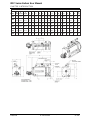
MFC Series – Dimensions
Model
A
(Width)
B
(Length)
C
(Height)
D
E
F
G
H
I
J
K
L
M
N
O
P
Q
R
S
(REF)
MFC
3000
54.3”
167.6”
84.0”
63.0”
126.4”
6.6”
72.9”
0.6”
12.6”
35.2”
73.0”
48.9”
5.0”
0.6”
18.1”
6.5”
27.6”
6.9”
27.2”
MFC
4000
58.7"
170.1”
88.3”
66.1”
129.0”
7.3”
75.4”
4.5”
16.2”
36.2”
76.2”
48.9”
3.4”
0.5”
17.3”
6.4”
27.4”
6.9”
29.3”
MFC
5000
58.7"
182.3”
88.3”
66.1”
141.2”
7.3”
75.4”
4.5”
16.2”
36.2”
76.2”
49.3”
3.4”
0.5”
17.3”
6.4”
35.6”
6.9”
29.3”
MFC
6000
70.9"
185.0”
101.1”
76.8”
143.8”
8.5”
87.1”
3.1”
22.8”
40.9”
86.8”
50.8”
4.4”
1.1”
21.1”
6.6”
53.2”
6.7”
35.4”
MFC
8000
70.9"
216.3”
102.3”
76.8”
163.5”
8.5”
87.1”
7.8”
22.8”
40.9”
86.8”
53.8”
3.1”
1.1”
18.1”
7.2”
55.9”
7.1”
35.4”
MFC
10000
70.9”
236.0”
102.3”
76.8”
183.2”
8.5”
87.1”
7.8”
22.8”
40.9”
86.8”
52.7”
3.0”
1.1”
18.0”
7.2”
70.9”
7.9”
35.4”

MFC Series Boilers User Manual
CHAPTER 3 - INSTALLATION P
OMM-0104_94 AERCO International, Inc. • 100 Oritani Dr. • Blauvelt, NY 10913 Page 15 of 170
GF-146 Ph.: 800-526-0288 12/29/2015
SECTION 3: Installation
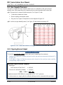
3.1 Receiving The Unit
Each MFC Series boiler is shipped as a double crated unit, comprised of boiler and Stainless
Steel 4
th
Pass. The shipping weight for the MFC Series boiler is as follows for each model:
MFC
3000
MFC 4000
MFC 5000
MFC 6000
MFC 8000
MFC 10000
SHIPPING WEIGHT LBS.
7,190 9,768 10,758 13,882 15,708 18,700
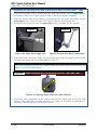
The unit must be moved with the proper rigging equipment for safety and to avoid equipment
damage. The unit should be completely inspected for evidence of shipping damage and
shipment completeness at the time of receipt from the carrier and before the bill of lading is
signed.
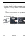
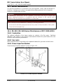
3.2 Moving & Unpacking the Unit
While packaged in the shipping container, the unit can be moved using a forklift. Refer to the
chart above in order to properly size forklift or other necessary equipment that may be required
in order to move the unit.
Carefully unpack the unit taking care not to damage the unit enclosure when cutting away
packaging materials
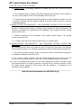
The following accessories come standard with each unit and are either factory installed on the
unit or packed separately with the unit:
MFC Series Accessories
ITEM QUANTITY PART NO. DESCRIPTION
1
See Table A
See Table A
Relief valve
2
See Table A
See Table A
Pipe Nipple
3
See Table A
See Table A
Bushing
4
1
123675-2
Tridicator
5
1
121700
Low Water Cut Off
6
1
24441
Condensate Trap
7
1
64115
Aquastat
8
1
64116
Manual Reset Aquastat
9
1
99235
Thermowell

MFC Series Boilers User Manual
CHAPTER 3 - INSTALLATION
Page 16 of 170 AERCO International, Inc. • 100 Oritani Dr. • Blauvelt, NY 10913 OMM-0104_94
12/29/2015 Ph.: 800-526-0288 GF-146
Table A - MFC Series Accessories
Refer to the MFC Boiler Field Assembly (TID-0164) for more information.

MFC Series Boilers User Manual
CHAPTER 3 - INSTALLATION P
OMM-0104_94 AERCO International, Inc. • 100 Oritani Dr. • Blauvelt, NY 10913 Page 17 of 170
GF-146 Ph.: 800-526-0288 12/29/2015
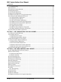
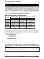
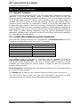
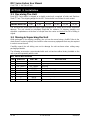
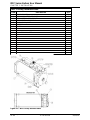
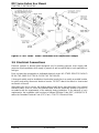
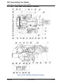
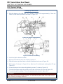
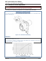
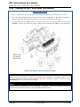
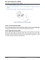
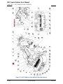
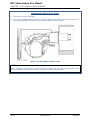
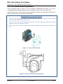
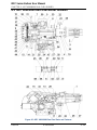
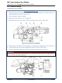
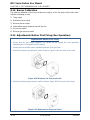
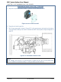
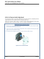
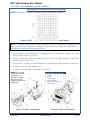
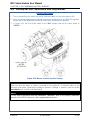
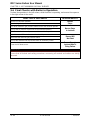
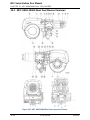
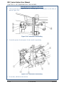
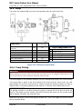
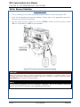
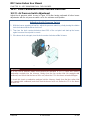
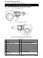
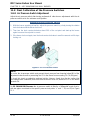
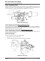
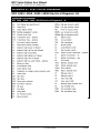
MFC Factory Installed Parts
ITEM DESCRIPTION QTY
1
BODY BOILER
1
2
STAINLESS STEEL 4TH PASS
1
3
CONNECTION PIPE FRONT
1
4
CONNECTION PIPE REAR
1
5
EXPANSION JOINT
1
6
SCREW
32
7
NUTS
32
8
CONNECTION PIPE GASKETS
4
9
ELBOW
2
10
BOILER DRAIN PIPE
1
11
BOILER DRAIN PIPE
1
12
THERMOINSULATING MATERIAL
KIT FOR BURNER HEAD
1
13
SCREW BETWEEN STAINLESS STEEL 4TH PASS AND BOILER
9
14
LARGE WASHERS BETWEEN
STAINLESS STEEL 4TH PASS AND
9
15
CONN. PIPE SUPPORT
2
16
SCREWS
4
17
NUTS for CONN. PIPE
4
18
LOCK WASHERS for CONN. PIPE
8
19
TUBE CLEANING BRUSH
1
20
DOOR OPENING TOOL
1
Figure 2-1: MFC Factory Installed Parts

MFC Series Boilers User Manual
CHAPTER 3 - INSTALLATION
Page 18 of 170 AERCO International, Inc. • 100 Oritani Dr. • Blauvelt, NY 10913 OMM-0104_94
12/29/2015 Ph.: 800-526-0288 GF-146
3.3 Site Preparation
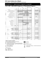
Electrical Requirements 3.3.1
(Refer to MFC Electrical Guide; GF-148-E / TAG-0077)
MFC Series boilers require 3
∅
for the burner and include a step-down transformer as standard
to provide 120VAC power to the control portion of the burner. Voltage requirements for each
model are shown in the tables below:
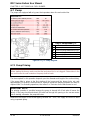
Multi-Fuel (Gas-Oil) Power Requirements (Amperage)
MFC
Burner
208/3∅/60
460/3∅/60
575/3∅/60
3000
RLS120
20.0
15.0
15.0
4000
RLS160
30.0
15.0
15.0
5000
RLS160
30.0
15.0
15.0
6000
RLS160
30.0
15.0
15.0
8000
RLS300
40.0
20.0
15.0
10000
RLS300
40.0
20.0
15.0
Gas Burner Power Requirements (Amperage)
MFC
Burner
208/3∅/60
460/3∅/60
575/3∅/60
3000
RS70
15.0
15.0
15.0
4000
RS100
15.0
15.0
15.0
5000
RS130
15.0
15.0
15.0
6000
RS190
20.0
15.0
15.0
8000
RS250
30.0
15.0
15.0
10000
RS300
30.0
15.0
15.0
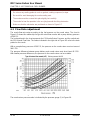
Natural Gas Requirements 3.3.2
(Refer to MFC Fuel Guide; GF-148-G / TAG-0078)
MFC boilers must have access to a Natural Gas line with the following minimum pressures with
the unit at FULL FIRE:
• MFC 3000 = 14” W.C.
• Other MFC Models = 1 psi.

MFC Series Boilers User Manual
CHAPTER 3 - INSTALLATION P
OMM-0104_94 AERCO International, Inc. • 100 Oritani Dr. • Blauvelt, NY 10913 Page 19 of 170
GF-146 Ph.: 800-526-0288 12/29/2015
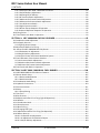
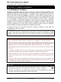
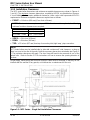
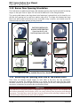
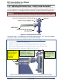
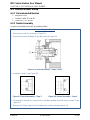
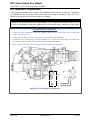
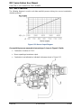
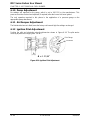
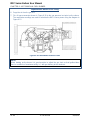
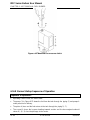
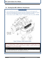
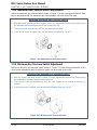
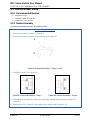
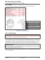
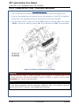
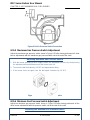
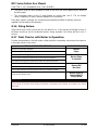
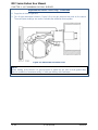
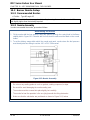
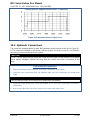
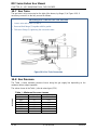
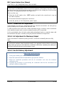
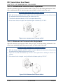
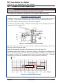
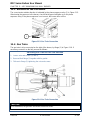
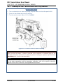
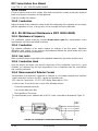
Installation Clearances 3.3.3
The MFC series boiler dimensions and minimum acceptable clearances are shown in Figures 4-
1 and 4-2. The minimum clearance dimensions, required by AERCO, are listed below. However,
if Local Building Codes require additional clearances, these codes shall supersede AERCO’s
requirements. Minimum acceptable clearances required are as follows:
• FRONT: = 24 inches (610 mm) (From front of blower).
NOTE: This is a minimum requirement per NFPA. If a tube must be replaced, the following
minimum front door clearances are required:
MFC 3000
80” (2032 mm)
MFC 4000 - 5000
92” (2336.8 mm)
MFC 6000 - 10000
133” (3378.2 mm)
• SIDES: = 24 inches (610 mm)
•
REAR: = 24 inches (610 mm)
•
TOP: = 12 inches (457 mm) from top of secondary inlet (high temp.) pipe connection.
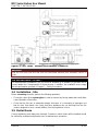
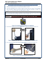
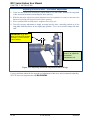
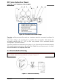
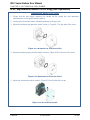
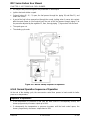
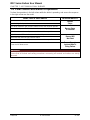
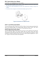
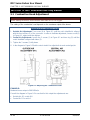
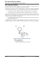
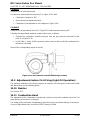
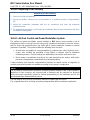
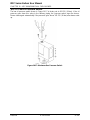
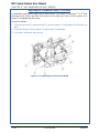
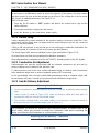
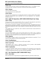
NOTE:
MFC Series boilers may be installed side by side with a minimum 6" side clearance, as long as
there is access to the rear of the units. Note the necessary burner door orientation per Figure 3-
2. The perimeter clearances still apply. The door hinge will need to be reversed on one of the
paired units. Refer to Section 3.11 for instructions on how to reverse the opening direction of
the door.
All gas piping, water piping and electrical conduit or cable must be arranged so that they do not
interfere with the removal of any panels, or inhibit service or maintenance of the unit.
Figure 3-1: MFC Series – Single Unit Installation Clearances

MFC Series Boilers User Manual
CHAPTER 3 - INSTALLATION
Page 20 of 170 AERCO International, Inc. • 100 Oritani Dr. • Blauvelt, NY 10913 OMM-0104_94
12/29/2015 Ph.: 800-526-0288 GF-146
Figure 3-2: MFC Series – Multiple Unit Installation Clearances
WARNING:
Keep the unit area clear and free from all combustible materials and flammable vapors or
liquids.
FOR MASSACHUSSETTS ONLY:
For Massachusetts installations, the unit must be installed by a plumber or gas-fitter that is
licensed within the Commonwealth of Massachusetts. In addition, the installation must comply
with all requirements specified in Chapter 1 – Safety Precautions.
3.4 Installation - Site
Before connecting the boiler, perform the following operations:
•
Thoroughly clean all the system pipes in order to remove any foreign matter that could affect
correct operation of the boiler.
•
Check that the flue has an adequate draught, that there is no narrowing of passages and
that it is free from debris; also check that other appliances do not discharge into the flue
(unless designed to serve several utilities). See the regulations in force.
3.5 Boiler Room
Current regulations must always be observed. Premises in which boilers will be installed should
be sufficiently ventilated and permit access for maintenance operations.
Page is loading ...
Page is loading ...
Page is loading ...
Page is loading ...
Page is loading ...
Page is loading ...
Page is loading ...
Page is loading ...
Page is loading ...
Page is loading ...
Page is loading ...
Page is loading ...
Page is loading ...
Page is loading ...
Page is loading ...
Page is loading ...
Page is loading ...
Page is loading ...
Page is loading ...
Page is loading ...
Page is loading ...
Page is loading ...
Page is loading ...
Page is loading ...
Page is loading ...
Page is loading ...
Page is loading ...
Page is loading ...
Page is loading ...
Page is loading ...
Page is loading ...
Page is loading ...
Page is loading ...
Page is loading ...
Page is loading ...
Page is loading ...
Page is loading ...
Page is loading ...
Page is loading ...
Page is loading ...
Page is loading ...
Page is loading ...
Page is loading ...
Page is loading ...
Page is loading ...
Page is loading ...
Page is loading ...
Page is loading ...
Page is loading ...
Page is loading ...
Page is loading ...
Page is loading ...
Page is loading ...
Page is loading ...
Page is loading ...
Page is loading ...
Page is loading ...
Page is loading ...
Page is loading ...
Page is loading ...
Page is loading ...
Page is loading ...
Page is loading ...
Page is loading ...
Page is loading ...
Page is loading ...
Page is loading ...
Page is loading ...
Page is loading ...
Page is loading ...
Page is loading ...
Page is loading ...
Page is loading ...
Page is loading ...
Page is loading ...
Page is loading ...
Page is loading ...
Page is loading ...
Page is loading ...
Page is loading ...
Page is loading ...
Page is loading ...
Page is loading ...
Page is loading ...
Page is loading ...
Page is loading ...
Page is loading ...
Page is loading ...
Page is loading ...
Page is loading ...
Page is loading ...
Page is loading ...
Page is loading ...
Page is loading ...
Page is loading ...
Page is loading ...
Page is loading ...
Page is loading ...
Page is loading ...
Page is loading ...
Page is loading ...
Page is loading ...
Page is loading ...
Page is loading ...
Page is loading ...
Page is loading ...
Page is loading ...
Page is loading ...
Page is loading ...
Page is loading ...
Page is loading ...
Page is loading ...
Page is loading ...
Page is loading ...
Page is loading ...
Page is loading ...
Page is loading ...
Page is loading ...
Page is loading ...
Page is loading ...
Page is loading ...
Page is loading ...
Page is loading ...
Page is loading ...
Page is loading ...
Page is loading ...
Page is loading ...
Page is loading ...
Page is loading ...
Page is loading ...
Page is loading ...
Page is loading ...
Page is loading ...
Page is loading ...
Page is loading ...
Page is loading ...
Page is loading ...
Page is loading ...
Page is loading ...
Page is loading ...
Page is loading ...
Page is loading ...
Page is loading ...
Page is loading ...
Page is loading ...
Page is loading ...
Page is loading ...
Page is loading ...
Page is loading ...
Page is loading ...
-
 1
1
-
 2
2
-
 3
3
-
 4
4
-
 5
5
-
 6
6
-
 7
7
-
 8
8
-
 9
9
-
 10
10
-
 11
11
-
 12
12
-
 13
13
-
 14
14
-
 15
15
-
 16
16
-
 17
17
-
 18
18
-
 19
19
-
 20
20
-
 21
21
-
 22
22
-
 23
23
-
 24
24
-
 25
25
-
 26
26
-
 27
27
-
 28
28
-
 29
29
-
 30
30
-
 31
31
-
 32
32
-
 33
33
-
 34
34
-
 35
35
-
 36
36
-
 37
37
-
 38
38
-
 39
39
-
 40
40
-
 41
41
-
 42
42
-
 43
43
-
 44
44
-
 45
45
-
 46
46
-
 47
47
-
 48
48
-
 49
49
-
 50
50
-
 51
51
-
 52
52
-
 53
53
-
 54
54
-
 55
55
-
 56
56
-
 57
57
-
 58
58
-
 59
59
-
 60
60
-
 61
61
-
 62
62
-
 63
63
-
 64
64
-
 65
65
-
 66
66
-
 67
67
-
 68
68
-
 69
69
-
 70
70
-
 71
71
-
 72
72
-
 73
73
-
 74
74
-
 75
75
-
 76
76
-
 77
77
-
 78
78
-
 79
79
-
 80
80
-
 81
81
-
 82
82
-
 83
83
-
 84
84
-
 85
85
-
 86
86
-
 87
87
-
 88
88
-
 89
89
-
 90
90
-
 91
91
-
 92
92
-
 93
93
-
 94
94
-
 95
95
-
 96
96
-
 97
97
-
 98
98
-
 99
99
-
 100
100
-
 101
101
-
 102
102
-
 103
103
-
 104
104
-
 105
105
-
 106
106
-
 107
107
-
 108
108
-
 109
109
-
 110
110
-
 111
111
-
 112
112
-
 113
113
-
 114
114
-
 115
115
-
 116
116
-
 117
117
-
 118
118
-
 119
119
-
 120
120
-
 121
121
-
 122
122
-
 123
123
-
 124
124
-
 125
125
-
 126
126
-
 127
127
-
 128
128
-
 129
129
-
 130
130
-
 131
131
-
 132
132
-
 133
133
-
 134
134
-
 135
135
-
 136
136
-
 137
137
-
 138
138
-
 139
139
-
 140
140
-
 141
141
-
 142
142
-
 143
143
-
 144
144
-
 145
145
-
 146
146
-
 147
147
-
 148
148
-
 149
149
-
 150
150
-
 151
151
-
 152
152
-
 153
153
-
 154
154
-
 155
155
-
 156
156
-
 157
157
-
 158
158
-
 159
159
-
 160
160
-
 161
161
-
 162
162
-
 163
163
-
 164
164
-
 165
165
-
 166
166
-
 167
167
-
 168
168
-
 169
169
-
 170
170


Aerco MFC 4000 User manual
- Type
- User manual
Ask a question and I''ll find the answer in the document
Finding information in a document is now easier with AI
Related papers
-
Aerco MFC 8000 Installation And Startup Manual
-
-
-
-
-
Aerco Benchmark BMK 5000 DF User manual
-
-
-
-
Aerco Benchmark BMK 1500 User manual
Other documents
-
Riello RL28/M Installation guide
-
PVI Industries Power Flame Owner's manual
-
BALTUR Minicomist 7 User manual
-
Precision FPS-62-100 Installation and Operating Instruction
-
Riello RLS 28 Installation, Use And Maintenance Manual
-
Riello BG7.1D 1/230/50 Installer Manual
-
 Nu-Way PO660 Installation & Maintenance Manual
-
-
Riello RLS 70 Installation guide
-
Eclipse Minnox Operating instructions
