Page is loading ...

••
Be sure to read this installation manual thoroughly prior to installation.
••
If installation methods or non-standard parts not specified in this installation manual are used, accidents or injury
may result.
••
Specialized techniques and expertise are required in order to install the speaker that this product is installed to.
Be sure to ask a qualified technician to carry out installation work.
••
Installation of the speaker should always be carried out by two or more people.
Be sure to keep this manual after the installation for later reference.
JAPANESE
GERMAN FRENCH ITALIAN SPANISHENGLISH
Contents
Contents
Tools used 2
For your safety in using this product 3
Accessories 2
Installation 4
INSTALLATION MANUAL: 090003-2883B700
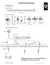
CEILING BRACKET
After all installation and connection work has been completed, please give this installation manual to the customer.
The installation screws used for installing the bracket and wires to the ceiling are not provided as accessories with
this product. (Bracket installation hole diameter: 7 mm)
To the installing technician:
When performing the installation 4
Cautions on use 3
INSTALLATION MANUAL

Accessor
Accessor
ies
ies
T
T
ools used
ools used
Have the following tools ready before commencing installation work.
Have the following tools ready before commencing installation work.
6
– 2 –
JAPANESE
ENGLISH GERMAN FRENCH ITALIAN SPANISH
••
Phillips screwdriver (Plus tip)
CB1 components
Spacer
X1
1
Bracket
X1
2
Wire
X1
3
Screw(binding M5 x 8)
X4
4 5
Screw (TD510 for wires)
(binding M4 x 8) X1
Screw (TD508 II for wires)
(binding M5 x 8) X1
••
Allen key
(Nominal size 1.5 mm)
(For cover wire)
••
Phillips screwdriver (Plus tip)
••
Allen key
(Nominal size 3 mm)
(For neck holding bolt)
••
Awl
(or drill)
••
Stubby screwdriver
(Plus tip)
••
Scissors
••
Tape
(Paper tape or similar)
••
Screw
(For installing bracket to
ceiling) X3 or more
150 mm or more 90 mm or more
Used for TD510 Used for TD508 II
••
Screw
(For securing drop-prevention
wire to ceiling) X1
Check that all of the following accessories are present before installation.
Check that all of the following accessories are present before installation.
Ceiling installation screws are not included.
Ceiling installation screws are not included.
••
Allen key
(Supplied with speaker, used
for speaker angle adjustment)

– 3 –
The following WARNING and CAUTION signs are used throughout this manual as well as on the product. These signs
alert the installer and users of important safety information to avoid risk of injury and damages to the product. Please
become familiar with these symbols and their associated information before proceeding to the assembly instructions of
this manual.
This "Warning" sign indicates a situation in which incorrect handling may result in death or
serious personal injury.
This "Caution" sign indicates a situation in which incorrect handling may result in personal
injury or may result solely in damage to property.
JAPANESE
GERMAN FRENCH ITALIAN SPANISHENGLISH
••
This product is a ceiling suspension bracket for TD508
and TD510 speakers. Do not use it for any other
applications, otherwise insecure installation could cause it
to fall down and injury may result.
••
Do not drop or drag this unit while assembling or carrying it.
Pushing over or dragging the product can result in an injury
or cause damage to the floor.
••
If installing this unit high up off the floor, be sure to secure it adequately in place. If it is not secured adequately, it may fall down
and cause injury.
••
Check the structure of installation location to make sure that the materials used are strong enough to bear the combined weight
of the speaker and ceiling bracket. If the installation location is not strong enough, the speaker may fall down due to vibration,
and serious injury could result.
••
Accessory parts including wires are provided as a safety measure to prevent the speaker from falling down once it has been
installed. Be sure to attach these wires to ensure safety. If this is not done, the screws may become loosened due to vibration,
and the speaker may fall down and serious injury could result.
••
This product is a ceiling suspension bracket for speakers. Do not use it for other purposes.
••
The speaker is heavy, so be careful when handling it.
••
Be careful not to let the speaker fall from this product.
••
Use a soft cloth soaked in neutral detergent to wipe the speaker if it becomes dirty. Do not use liquid solvents such
as alcohol or thinner to clean this product.
••
Do not climb onto or hang from the product. Take particular
care if children are around. If this is not observed, the
speaker may fall down or tip over and cause serious injury.
••
After installing the speaker, periodically check the angle
bracket and speaker bracket for any looseness, and tighten
them if required as a safety measure.
This section contains information that can help to prevent problems and damage to the
unit, and also contains other useful information.
Warning
Caution
Tip
Caution
Warning
F
F
or y
or y
our saf
our saf
ety in using this product
ety in using this product
Cautions on use
Cautions on use

– 4 –
JAPANESE
ENGLISH GERMAN FRENCH ITALIAN SPANISH
Be sure to leave some space in between the speaker and the wall so that the speaker and wall do not touch.
Base cover
Speaker base
Leave enough space.
Speaker
Bracket
2
Spacer
1
Ceiling
Wall
Speaker wire (for diameter of 7 mm or more)
Speaker wire (for diameter of less than 7 mm)
5 3/4 in. (134 mm) (TD508 II )
8 in. (202 mm) (TD510)
Caution
Ci
Leave enough
space.
Installation 5
Installation to a ceiling 7
Adjusting the angle 6
Template for determining bracket installation position
Caution
When perf
When perf
or
or
ming the installation
ming the installation
Installation
Installation

– 5 –
JAPANESE
GERMAN FRENCH ITALIAN SPANISHENGLISH
Remove the speaker from the speaker base.
(For TD508 II only)
4
Remove the base cover.
2
Base cover
Speaker
Remove the hexagon head screw which is used for
securing the base cover drop-prevention wire from the
speaker.
3
For the TD510, do not remove the speaker from the
speaker base.
Drop-prevention wire
Hexagon head screw
Speaker (TD508 II)
Speaker base
Angle
adjustment
screw
The hexagon head screw which is removed will be used
later. Be careful not to lose the hexagon head screw
after removing it.
– Installation –
Remove the screws from the bottom of the speaker
base.
1
Speaker
Screw X4
Speaker base
The screws which are removed will not be used.
Give them to the customer to keep safely.
Tip
Tip
Tip

– 6 –
JAPANESE
ENGLISH GERMAN FRENCH ITALIAN SPANISH
Speaker
Remove the neck holding bolt at the base of the
speaker.
7
Neck holding bolt
Use the Allen key which is supplied with the speaker to
loosen the angle adjustment screw underneath the
speaker.
8
Speaker
Angle adjustment
screw
Allen key
Joint
Slide the speaker to the right slightly to disengage the
tabs of the joint.
9
••
The removed neck holding bolt will not be re-used.
••
The neck holding bolt limits the angle of the speaker
when the speaker is set up on the floor, and it
prevents the speaker from tipping over. After
removing it, give it to the customer to keep safely.
••
Turn the speaker upside-down when adjusting the
angle of the speaker.
••
The right side in the instructions signifies the right side
of the speaker when looking at it from the front when it
is in its normal position.
Move slightly
[Right side] [Left side]
Install the wire to the speaker.
5
••
TD508 II speakers only: Use the screw (binding M5 x
8) that is included with the bracket as the screw
marked .
••
Use the screws (binding M4 x 8) for the TD510
speaker.
Make sure that the screw installation holes are correct.
••
Be sure to attach the wire securely to the speaker and
the ceiling so that the speaker does not fall down.
Wire
3
Screw
5
For the TD510
Screw mounting hole
Install the speaker to the speaker base.
(For TD508 II only)
6
Screwdriver
For the TD508 II
Screw
6
Screwdriver
Wire
3
Caution
Tip
Tip
5
6
– Adjusting the angle –

– 7 –
JAPANESE
GERMAN FRENCH ITALIAN SPANISHENGLISH
••
The tabs on the joint of the speaker base should fit into
the slots in the speaker as shown in the illustration. If
the tabs are not inserted into the slots, the speaker will
not be fully secured and it may fall down and damage
may result.
••
If the mark on the speaker base is aligned with the
index marks on the speaker, then the tabs on the
speaker base joint will be correctly aligned with the
slots in the speaker.
– Installation to a ceiling –
Use the template to determine the speaker installation
position on the ceiling inside the room, and then use
tape to attach the template to the ceiling.
12
Use an awl or similar tool to mark the positions of the
bracket mounting holes.
13
Tabs on speaker base joint
The tabs must be inserted into
the slots.
Template
Remove the template from the ceiling.
14
Set the speaker to the desired angle.
10
Securely tighten the angle adjustment screw.
11
Align with the
index marks
1 forward step
6 backward steps
Speaker
Speaker base
Joint
40 in.
(1m)
Speaker base
Speaker
Speaker wire
(for diameter of 7 mm or more)
Caution
••
When adjusting the angle of the speaker, align the
mark at the base of the speaker with the index
marks on the speaker. If the mark is not aligned with
the index marks when adjusting the angle of the
speaker, the joints of the speaker and speaker base
will become damaged.
••
The angle of the speaker can be adjusted to one
forward position and six backward positions.
••
Turn the speaker upside-down and move the speaker
base to adjust the angle of the speaker.
Tip
Use scissors or similar to cut the template.
Tip
Speaker wire
(for diameter of less than 7 mm)

– 8 –
JAPANESE
ENGLISH GERMAN FRENCH ITALIAN SPANISH
Peel off the backing paper from the double-sided tape
on the spacer, and attach the spacer to the bracket.
15
Install the bracket at the speaker installation position
using the screws (sold separately).
16
••
Install the bracket securely so that the speaker will not
fall down.
••
The screws which are used to install the bracket to the
ceiling or wall are not provided with the bracket, so
purchase them separately.
••
When securing the bracket to the ceiling or wall with
the screws, do not overtighten the screws, otherwise
the bracket will become bent and it may not be
possible to install the speaker. Take care during
installation so that the screws do not become
overtightened.
••
When installing the bracket to the ceiling or wall, vary
the positions and number of screws used in
accordance with the strength of the ceiling or wall and
the locations of beams.
••
If the installation location is not strong enough when
the standard installation holes are made, install more
screws (sold separately) using the slits marked with
in order to increase the installation strength.
Route the speaker wires.
17
••
To make it easier to connect the speaker wires to the
speaker, leave about 40 inches (1 m) of speaker wire
hanging out.
••
If the speaker wires are routed through the middle of
the bracket , it will improve the outer appearance.
(for diameter of less than 7 mm)
2
Bracket
2
Spacer
1
Speaker installation position
Screws
(sold separately)
Bracket
2
Bracket
2
Approx. 40 in.
(1m)
Bracket
2
Spacer
1
Standard
installation holes
Caution
Tip
Tip
Speaker wire
(for diameter of 7 mm or more)
Speaker wire
(for diameter of less than 7 mm)

– 9 –
JAPANESE
GERMAN FRENCH ITALIAN SPANISHENGLISH
Connect the speaker wires to the speaker.
18
Align the projections on the speaker with the slots in
the bracket.
19
Turn the speaker to hook the projections on the
speaker into the bracket to secure the speaker.
20
Speaker wire
Speaker wire
Speaker
Speaker
Bracket
2
Bracket
2
Speaker
(underside)
Align the projections on the speaker
with the slots in the bracket.
••
Align the projections on the speaker with the slots in
the bracket, and then securely install the speaker to
the bracket. If the speaker is not installed securely
enough, it may fall down.
••
Be careful not to clamp the speaker wires between the
speaker, bracket or ceiling.
Speaker wire (for diameter of 7 mm or more)
Speaker wire (for diameter of less than 7 mm)
Speaker
Speaker wire
Speaker wire
Caution
••
If the speaker wires are routed through the bracket
and speaker neck, they will not easily visible from
outside which will improve the outer appearance of
the speaker. (for diameter of less than 7 mm)
••
When connecting the speaker wires, insert the ends of
the speaker wires correctly so that they do not touch
neighboring terminals.
Tip
When securing the speaker to the bracket, turn the
speaker in the direction of the arrow marked on the
speaker base. The illustration shows the TD508 II.
Tip
2

– 10 –
JAPANESE
ENGLISH GERMAN FRENCH ITALIAN SPANISH
Wire
3
Securely install the speaker to the bracket by using the
stubby screwdriver to tighten the screws.
21
Speaker
Bracket
2
Install the drop-prevention wire to the ceiling.
22
Screw X4
4
Install the drop-prevention wire to the ceiling in a place
it can reach which is strong, such as a beam location.
Install the drop-prevention wire securely to the ceiling so
that the speaker will not fall down.
Speaker
Screws
(sold separately)
••
The speaker can be adjusted to within 10° on each
side by loosening the screws.
••
When adjusting the direction of the speaker, only
loosen the screws. They should never be removed. If
all of the screws are removed, the speaker may fall
down.
Stubby screwdriver
Caution
Caution
Tip

– 11 –
JAPANESE
GERMAN FRENCH ITALIAN SPANISHENGLISH
Base cover
Speaker
Install the base cover to the speaker base.
24
Base cover
Speaker
Install the base cover drop-prevention wire to the
speaker base by carrying out step in reverse.
23
Drop-prevention wire
Hexagon
head screw
3
Drop-prevention wire
Speaker base

– 12 –
JAPANESE
ENGLISH GERMAN FRENCH ITALIAN SPANISH
– Template for determining bracket installation position –
Route the speaker wires before installing the spacer and the bracket to the ceiling.
(Bracket installation hole diameter: 7 mm)
Front of speaker (standard position)
Front of speaker (standard position)
Use an awl or similar tool to mark the
positions of the bracket installation
screws on the ceiling.
Cut out the shaded section.
60°
60°
60°
60°
45° 45°
30° 30°
45°
45°
30°
30°
Use an awl or similar tool
to mark the positions of the
bracket installation screws on
the ceiling.
Use an awl or similar tool to mark the
positions of the bracket installation
screws on the ceiling.
Tip
/