Page is loading ...

Millerfi
March
1992
FORM:
OM-152
308
MODEL:
Computer
Interface
(Per
NSPR
9860)
flLE
COPY
RETURN
TO
FOLDER
OWNERS
MANUAL
IMPORTANT:
Read
and
understand
the
entire
contents
of
both
this
manual
and
the
power
source
manual
used
with
this
unit,
with
special
emphasis
on
the
safety
material
throughout
both
manuals,
before
installing,
operating,
or
maintaining
this
equipment.
This
unit
and
these
instructions
are
for
use
only
by
persons
trained
and
experienced
in
the
safe
operation
of
welding
equip
ment.
Do
not
allow
untrained
persons
to
install,
operate,
or
maintain
this
unit.
Contact
your
distributor
if
you
do
not
fully
understand
these
instructions.
MILLER
ELECTRIC
Mfg.
Co.
A
Miller
Group
Ltd.,
Company
P.O.
Box
1079
Appleton,
WI
54912
USA
Tel.
414.734.9821
PRINTED
IN
US
A

LIMITED
WARRANTY
EFPECTIVE:
AUGUST
6.
1990
L.
This
warranty
supersedes
all
previous
MILLER
warranties
and
is
exclusive
with
no
other
guarantees
or
warranties
expressed
or
implied.
LIMITED
WARRANTY
Subiect
to
the
terms
and
conditions
hereof.
MILLER
Electric
Mfg.
Co.,
Appleton.
Wisconsin
war
rants
to
its
Distributor/Dealer
that
all
new
and
unused
Equipment
furnished
by
MILLER
is
free
from
defect
in
workmanship
and
material
as
of
the
time
and
place
of
delivery
by
MILLER.
No
warranty
is
made
by
MILLER
with
resoect
to
engines,
trade
accessories
or
other
items
manufactured
by
others.
Such
engines,
trade
accessories
and
other
items
are
sold
subject
to
the
warranties
of
their
respective
manufacturers,
if
any.
All
engines
are
warrantied
by
their
manufacturer
for
two
years
from
date
of
original
purchase,
except
Deutz
engines
which
have
a
one
year,
2000
hour
warranty.
Except
as
specified
below.
MILLERs
warranty
does
not
apply
to
components
having
normal
useful
life
of
less
than
one
(1)
year.
such
as
spot
welder
tips,
relay
and
contactor
points.
MILLERMATIC
parts
that
come
in
contact
with
the
welding
wire
including
nozzles
and
nozzle
insulators
where
failure
does
not
result
from
defect
in
workmanship
or
material.
MILLER
shall
be
required
to
honor
warranty
claims
on
war
ranted
Equipment
in
the
event
of
failure
resulting
from
a
defect
within
the
following
periods
from
the
date
of
delivery
of
Equipment
to
the
original
user:
-
1.
Arc
welders,
power
sources,
robots,
and
1
year
components
2.
Load
banks
1
year
3.
Original
main
power
rectifiers
3
years
(labor
1
year
only)
4.
All
welding
guns,
feeder/guns
and
torches
.
.
.
90
days
5.
All
other
MILLERMATIC
Feeders
1
year
6.
Replacement
or
repair
parts,
exclusive
of
labor
60
days
7.
Batteries
6
months
provided
that
MILLER
is
notified
in
writing
within
thirty
(30)
days
of
the
date
of
such
failure.
As
a
matter
of
general
policy
only.
MILLER
may
honor
claims
submitted
by
the
original
user
within
the
foregoing
periods.
In
the
case
of
MILLERs
breach
of
warranty
or
any
other
duty
with
respect
to
the
quality
of
any
goods.
the
exclusive
remedies
therefore
shall
be,
at
MILLERs
option
(1)
repair
or
(21
replace.
ment
or,
where
authorized
in
writing
by
MILLER
in
appropriate
cases,
(3)
the
reasonable
cost
of
repair
or
replacement
at
an
authorized
MILLER
service
station
or
(4)
payment
of
or
credit
for
the
purchase
price
(less
reasonable
depreciation
based
upon
actual
use)
upon
return
of
the
goods
at
Customers
risk
and
expense.
MILLERs
option
of
repair
or
replacement
will
be
FOB..
Factory
at
Appleton,
Wisconsin,
or
F
O.B.
at
a
MILLER
authorized
service
facility,
therefore,
no
compensation
for
transportation
costs
of
any
kind
II
be
allowed.
Upon
receipt
of
notice
of
apparent
defect
or
failure.
MILLER
shall
instruct
the
claimant
on
the
warranty
claim
procedures
to
be
followed.
ANY
EXPRESS
WARRANTY
NOT
PROVIDED
HEREIN
AND
ANY
IMPLIED
WARRANTY.
GUARANTY
OR
REPRE
SENTATION
AS
TO
PERFORMANCE.
AND
ANY
REMEDY
FOR
BREACH
OF
CONTRACT
WHICH,
BUT
FOR
THIS
PROVISION,
MIGHT
ARISE
BY
IMPLICATION.
OPERATION
OF
LAW,
CUSTOM
OF
TRADE
OR
COURSE
OF
DEALING.
INCLUDING
ANY
IMPLIED
WARRANTY
OF
MERCHAN
TABILITY
OR
OF
FITNESS
FOR
PARTICULAR
PURPOSE.
WITH
RESPECT
TO
ANY
AND
ALL
EQUIPMENT
FURNISHED
BY
MILLER
IS
EXCLUDED
AND
DISCLAIMED
BY
MILLER.
EXCEPT
AS
EXPRESSLY
PROVIDED
BY
MILLER
IN
WRITING,
MILLER
PRODUCTS
ARE
INTENDED
FOR
ULTIMATE
PURCHASE
BY
COMMERCIALJINDIJSTRIAL
USERS
AND
FOR
OPERATION
BY
PERSONS
TRAINED
AND
EXPERIENCED
IN
THE
USE
AND
MAINTENANCE
OF
WELDING
EQUIPMENT
AND
NOT
FOR
CONSUMERS
OR
CONSUMER
USE.
MILLERS
WARRANTIES
DO
NOT
EXTEND
TO.
AND
NO
RESELLER
IS
AUTHORIZED
TO
EXTEND
MILLERS
WARRANTIES
TO.
ANY
CONSUMER.
i_U
RECEIVING-HANDLING
Before
unpacking
equipment,
check
carton
for
any
damage
that
may
have
occurred
during
shipment.
File
any
claims
for
loss
or
damage
with
the
delivering
carrier.
Assistance
for
filing
or
settling
claims
may
be
obtained
from
distributor
and/or
equipment
manufacturers
Transportation
Department.
When
requesting
information
about
this
equipment,
always
provide
Model
Designation
and
Serial
or
Style
Number.
Use
the
following
spaces
to
record
Model
Designation
and
Serial
or
Style
Number
of
your
unit.
The
information
is
located
on
the
rating
label
or
nameplate.
Model
__________
Serial
or
Style
No.
Date
of
Purchase
91

QM.152
308
392
RECEIVING-HANDLING
Before
unpacking
equipment,
check
carton
for
any
dam-
Use
the
following
spaces
to
record
the
Model
Designa
age
that
may
have
occurred
during
shipment.
File
any
tion
and
Serial
or
Style
Number
of
your
unit.
The
infor
claims
for
loss
or
damage
with
the
delivering
carrier.
mation
is
located
on
the
rating
label
or
the
nameplate.
Assistance
for
filing
or
settling
claims
may
be
obtained
from
the
distributor
and/or
the
equipment
manufactur-
Model
________________________________
ers
Transportation
Department.
Serial
or
Style
No.
_____________________
When
requesting
information
about
this
equipment,
al
ways
provide
the
Model
Description
and
Serial
or
Style
Date
of
Purchase
______________________
Number.
TABLE
OF
CONTENTS
Section
No
Page
No.
SECTION
1
SAFETY
PRECAUTIONS
AND
SIGNAL
WORDS
1-1.
General
Information
And
Safety
1
1-2.
Safety
Alert
Symbol
And
Signal
Words
1
SECTION
2
SPECIFICATIONS
2-1.
Description
1
SECTION
3
INSTALLATION
3-1.
Site
Selection
2
3-2.
Equipment
Installation
2
3-3.
Gas/Current
Sensing
Control
Interconnections
3
3-4.
Voltage
Sensing
Connections
3
3-5.
Robot
Interface
Welding
Power
Source
Connections
4
3-6.
Robot
Interface
Robot
Control
Unit
Connections
4
3-7.
Arc
Failure
Light
Terminal
Strip
Connections
4
3-8.
Welding
Wire
Installation
5
3-9.
Setting
DIP
Switches
On
DVC
Board
PCi
6
SECTION
4-OPERATOR
CONTROLS
4-1.
Power
Switch
7
4-2.
Jog
Push
Buttons
7
4-3.
Purge
Push
Button
7
4-4.
Voltmeter
7
4-5.
Wire
Speed
Meter
7
4-6.
Inductance
Meter
7
4-7.
Indicator
Lights
7
4-8.
Standard/Optima
Switch
7
4-9.
Inductance
Control
8
4-10.
Preflow,
Postflow,
And
Burnback
Time
Presets
8
SECTION
5
SEQUENCE
OF
OPERATION
5-1.
Input
Signals
From
Robot
Control
Unit
8
5-2.
Output
Signals
From
Robot
Interface
8

Section
No.
Page
No.
SECTION
6
MAINTENANCE
&
TROUBLESHOOTING
6-1.
Routine
Maintenance
8
6-2.
Overload
Protection
8
6-3.
Reinstallation
Of
Hub
Assembly
9
6-4.
Display
Board
PC4
Meter
Check
9
6-5.
Circuit
Board
Handling
Precautions
10
6-6.
Troubleshooting
10
6-7.
Use
Of
Indicator
Lights
For
Troubleshooting
12
SECTION
7-
ELECTRICAL
DIAGRAMS
Diagram
7-1.
Circuit
Diagram
For
Robot
Interface
13
Diagram
7-2.
Circuit
Diagram
For
Gas/Current
Sensing
Control
14
SECTION
8
PARTS
LIST
15
LIST
OF
CHARTS
AND
TABLES
Table
2-1.
Specifications
1
Table
6-1.
Troubleshooting
11

SECTION
1
SAFETY
PRECAUTIONS
AND
SIGNAL
WORDS
1-1.
GENERAL
INFORMATION
AND
SAFETY
1-2.
SAFETY
ALERT
SYMBOL
AND
SIGNAL
WORDS
A.
General
The
following
safety
alert
symbol
and
signal
words
are
Information
presented
in
this
manual
and
on
various
Ia-
used
throughout
this
manual
to
call
attention
to
and
den
bels,
tags,
and
plates
on
the
unit
pertains
to
equipment
tify
different
levels
of
hazard
and
special
instructions.
design,
installation,
operation,
maintenance,
and
J\~
This
safety
alert
symbol
is
used
with
the
signal
troubleshooting
which
should
be
read,
understood,
and
.
words
WARNING
and
CAUTION
to
call
atten
followed
for
the
safe
and
effective
use
of
this
equipment.
tion
to
the
safety
statements.
B.
Safety
WARNING
statements
identify
procedures
or
The
installation,
operation,
maintenance,
and
trouble-
practices
which
must
be
followed
to
avoid
seri
shooting
of
arc
welding
equipment
requires
practices
ous
personal
injury
or
loss
of
life.
and
procedures
which
ensure
personal
safety
and
the
safety
of
others.
Therefore,
this
equipment
is
to
be
in-
CAUTION
statements
identify
procedures
or
stalled,
operated,
and
maintained
only
by
qualified
per-
practices
which
must
be
followed
to
avoid
minor
sons
in
accordance
with
this
manual
and
all
applicable
personal
injury
or
damage
to
this
equipment.
codes
such
as,
but
not
limited
to,
those
listed
at
the
end
of
Section
1
Safety
Rules
For
Operation
Of
Arc
Weld-
IMPORTANT
statements
identify
special
instructions
ing
Power
Source
in
the
welding
power
source
Owners
necessary
for
the
most
efficient
operation
of
this
equip
Manual.
ment.
SECTION
2SPECIFICATIONS
Table
2-1.
Specifications
Component
Dimensions
Weight
Height
Width
Depth
Net
Ship
Robot
Interface
22-1/2
in.
(572
mm)
16-1/2in.
(419
mm)
6~1/4in.*
(159
mm)
38
lbs.
(17
kg)
Total
61
lbs.
(27.7
kg)
Gas/Current
Sensing
Control
4-1/2
in.
(108
mm)
5-1/2
in.
(140
mm)
10-1/2
in.
(267
mm)
5
lbs.
(2.3
kg)
Spool
Support
Assembly+
13-3/4
in.
(349
mm)
8-3/4
in.
(222
mm)
8-1/2
in.
(216
mm)
6
lbs.
(2.7
kg)
Add
2-1/4
in.
(57
mm)
for
brake
resistor.
+Spool
Support
without
optional
wire
reel.
Add
7/8
in.
(22
mm)
for
front
panel
knob.
2-1.
DESCRIPTION
volts,wire
feed
speed,
and
peak
amperage
or
induc
tance.
The
robot
interface control
is
designed
to
interface
with
a
The
gas/current
sensing
control
contains
the
gas
valve,
Hitachi/GE
robot
and
a
Maxtron
450
(NSPR
9863),
Arc
and
current
sensing
reed
relay.
Pak
350,
Deltaweld,
or
Maxtron
300
welding
power
These
components
function
with
the
robot
system
when
source.
This
unit
provides
digital
display
of
weld
using
the
Gas
Metal
Arc
Welding
(GMAW)
process.
OM-152
308
Page
1

SECTION
3-
INSTALLATION
3-1.
SITE
SELECTION
Select
an
installation
site
which
provides
the
following:
1.
Correct
input
power
supply
(see
unit
rating
label)
2.
Shielding
gas
supply
(if
applicable)
3.
Water
supply
(if
applicable)
4.
Adequate
ventilation
and
fresh
air
supply
5.
No
flammables
6.
A
clean
and
dry
area
7.
Proper
temperature
that
avoids
extremes
of
heat
or
cold
8.
Proper
airflow
around
unit
9.
Adequate
space
to
open
and
remove
cover
and
wrapper
for
installation,
maintenance,
and
repair
functions.
Mounting
holes
provide
the
capability
to
install
and
se
cure
the
system
components
in
a
permanent
location.
Table
2-1
gives
overall
dimensions.
3-2.
EQUIPMENT
INSTALLATION
A.
Supplied
Equipment
The
following
equipment
is
supplied
as
standard
and
re
quires
installation
or
assembly:
1.
Weld
Control
with
Gas/Current
Sensing
Control
Cord
and
Motor
Cord
2.
Gas/Current
Sensing
Control
3.
Hub
and
Spindle
Assembly
4.
Spindle
Support
5.
10
ft.
(3m)
Weld
ControlWelding
Power
Source
Interconnecting
Cords
6.
10
ft.
(3
m)
Gas
Hose
7.
Voltage
Sensing
Cord
B.
Equipment
Location
When
deciding
on
equipment
location,
consider
the
fol
lowing:
1.
The
equipment
must
be
mounted
to
a
structure
capable
of
supporting
the
weight
of
the
equip
ment.
2.
The
lead
lengths
of
the
cords
supplied
with
the
equipment
will
limit
the
area
in
which
the
equip
ment
can
be
located.
Some
cords
can
be
ex
tended
by
using
optional
extension
cords
(check
with
welding
equipment
distributor).
OM-152
308
Page
2
3.
The
interconnecting
cords
must
be
routed
so
that
they
are
not
caught,
pinched,
or
strained
during
welding
operations.
4.
One
weld
output
cable
must
be
routed
through
the
Gas/Current
Sensing
control.
5.
Welding
wire
must
be
routed
so
that
it
does
not
contact
the
weld
control
or
any
other
grounded
equipment.
C.
Equipment
Installation
Obtain
appropriate
mounting
brackets
or
adapter
plates
as
necessary
and
mounting
hardware.
Prepare
struc
ture
for
equipment
installation.
Secure
weld
control,
Gas/Current
Sensing
control,
and
all
other
equipment
onto
structures
in
the
welding
area.
0.
Hub
Installation
(Figure
3-1)
The
hub
assembly
is
supplied
with
the
robot
interface.
Remove
the
hub
assembly
from
the
shipping
carton,
and
install
it
as
follows:
1.
Remove
hex
nut
from
end
of
hub
support
shaft.
2.
Align
keyway
and
insert
hub
support
shaft
through
selected
hole
in
hub
support.
Hole
selec
tion
in
hub
support
depends
on
wire
spool
size.
Be
sure
the
brake
washers
are
properly
seated
in
the
hub.
3.
Reinstall
hex
nut
onto
support
shaft.
Tighten
hex
nut
until
a
slight
drag
is
fe!t
while
turning
hub.
4.
Install
welding
wire
according
to
Section
3-8.
~A26
870
Hub
Support
Shaft
Hub
Assemby
Brake
Washer
Hex
Nut
Hub
Support
Figure
3-1.
Hub
Assembly
Installation

B.
Weld
Cable
Connections
3-3.
GAS/CURRENT
SENSING
CONTROL
INTER
CONNECTIONS
(Figure
3-2)
a
WARNING:
ELECTRIC
SHOCK
can
kill.
Do
not
touch
live
electrical
parts.
Shut
down
unit,
welding
power
source,
and
robot,
and
disconnect
input
power
employing
lockout/tagging
procedures
before
making
interconnections.
Lockout/tagging
procedures
consist
of
padlock
ing
line
disconnect
switch
in
open
position,
re
moving
fuses
from
fuse
box,
or
shutting
off
and
red-tagging
circuit
breaker
or
other
disconnect
ing
device.
Gas/current
Sensing
Control
Receptacle
RC9
__________
14-Pin
Receptacle
RCI3
Strain
Relief
17.
Pin
Receptacle
RCI6
For
Electrode
Positive/Reverse
Polarity,
route
cable
from
welding
power
source
POSITIVE
weld
output
ter
minalto
the
gas/current
sensing
control,
through
the
cur
rent
sensing
reed
relay,
to
the
wire
drive
assembly,
and
connect
cable
to
weld
cable
terminal
(see
Motor/Drive
Assembly
Owners
Manual
for
location).
C.
Gas
Connections
Connect
hose
from
gas
regulator/flowmeter
(customer
supplied)
at
gas
source
to
IN
fitting
on
gas/current
sens
ing
control.
Connect
gas
hose
from
wire
drive
assembly
to
fitting
on
gas/current
sensing
control.
The
gas
flow
must
be
accurately
controlled
by
a
regulator/flowmeter
at
the
source.
D.
Motor
Connection
Align
keyways,
insert
14-pin
plug
from
motor
cord
into
matching
receptacle
RC7
on
gas/current
sensing
con
trol,
and
rotate
threaded
collar
fully
clockwise.
S
04
0
I
Voltage
Sensing
Receptacle
RC12
Robot
Control-
Robot
Interface
Receptacle
RC12
Figure
3-2.
Right
Side
View
A.
Robot
Interface
Gas/Current
Sensing
Control
Connections
Align
keyways,
insert
14-pin
Amp
plug
into
matching
receptacle
RC9
on
robot
interface,
and
rotate
threaded
collar
fully
clockwise.
2.
Align
keyways,
insert
16-pin
Amp
plug
into
matching
receptacle
RC16
on
gas/current
sens
ing
control,
and
rotate
threaded
collar
fully
clock
wise.
3-4.
VOLTAGE
SENSING
CONNECTIONS
(Figure
3-3)
1.
Align
keyway,
insert
4-socket
plug
into
matching
receptacle
RC12
on
robot
interface,
and
rotate
threaded
collar
fully
clockwise.
2.
Connect
lead
with
ring
terminal
to
wire
drive
as
sembly,
along
with
the
weld
cable
from
the
weld
ing
power
source,
as
shown
in
Figure
3-3.
3.
Connect
lead
with
clamp
to
the
workpiece.
00000
)0000
00000
)0000C
00000
)0000
00000
)0000~
00000
)0000
00000
)0000~
0
0~0
0
0
~b
0
00000
Weld
Cable
Lug
Location
Figure
3-3.
Voltage
Sensing
Connections
At
Wire
Drive
Assembly
OM-152
308
Page
3

a
a
3-3)
3-5.
ROBOT
INTERFACE
WELDING
POWER
SOURCE
CONNECTIONS
(Figures
3-2
And
WARNING:
ELECTRIC
SHOCK
can
kill.
Do
not
touch
live
electrical
parts.
Shut
down
unit,
welding
power
source,
and
robot,
and
disconnect
input
power
employing
lockout/tagging
procedures
before
making
interconnections.
Lockout/tagging
procedures
consist
of
padlock
ing
line
disconnect
switch
in
open
position,
re
moving
fuses
from
fuse
box,
or
shutting
off
and
red-tagging
circuit
breaker
or
other
disconnect
ing
device.
There
are
three
cords
supplied
for
interconnection
be
tween
the
robot
interface
and
welding
power
source.
Ex
amine
cords
and
select
proper
cord
for
the
connection.
A.
REMOTE
14
Connections
1.
Align
keyway,
insert
14-socket
plug
into
matching
receptacle
RC13
on
robot
interface,
and
rotate
threaded
collar
fully
clockwise.
2.
Align
keyway,
insert
14-pin
plug
into
matching
re
ceptacle
on
welding
power
source,
and
rotate
threaded
collar
fully
clockwise.
B.
REMOTE
17
Connections
1.
Align
keyway,
insert
17-socket
plug
into
matching
receptacle
RC16
on
robot
interface,
and
rotate
threaded
collar
fully
clockwise.
2.
Align
keyway,
insert
17-pin
plug
into
matching
re
ceptacle
on
welding
power
source,
and
rotate
thread
collar
fully
clockwise.
When
used
with
the
Maxtron
450,
place
the
welding
power
source
OUTPUT
(CONTACTOR)
switch
in
the
17/14
position,
the
ARC/INDUCTANCE
AND
CC/CV
switch
in
the
17
position,
the
A/V
switch
in
the
14
posi
tion,
and
the
Mode
switch
in
the
GMAW
position.
If
another
welding
power
source
is
used
and
is
equipped
with
a
REMOTE
14/17
selector
switch,
place
the
switch
in
the
REMOTE
14
position.
Make
connections
to
both
REMOTE
14
and
REMOTE
17
receptacles.
3-6.
ROBOT
INTERFACE
-
ROBOT
CONTROL
UNIT
CONNECTIONS
(Figure
3-2)
WARNING:
ELECTRIC
SHOCK
can
kill.
Do
not
touch
live
electrical
parts.
Shut
down
unit,
welding
power
source,
and
robot,
and
disconnect
input
power
employing
lockout/tagging
procedures
before
making
interconnections.
Lockout/tagging
procedures
consist
of
padlock
ing
line
disconnect
switch
in
open
position,
re
moving
fuses
from
fuse
box,
or
shutting
off
and
red-tagging
circuit
breaker
or
other
disconnect
ing
device.
1.
Obtain
a
proper
cord
and
24-socket
Amphenol
plug
(not
supplied).
2.
Connect
conductors
at
one
end
of
cord
to
appro
priate
sockets
in
plug.
3.
Align
keyway,
insert
24-socket
plug
into
matching
receptacle
on
robot
interface,
and
rotate
threaded
collar
fully
clockwise.
4.
Route
and
connect
conductors
at
remaining
end
of
cord
to
the
robot
control
unit.
The
input
and
output
signals
at
the
pins
of
receptacle
RC17
by
means
of
the
robot
interface
control
circuitry
are
as
follows:
Pin
A:
Digital
common
for
Pins
B,
C,
0,
E,
F,
and
K.
Pin
B:
Weld
Standby
signal;
contact
closure
with
re
spect
to
Pin
A.
Pin
C:
Current
Detect
signal
contact
closure
with
re
spect
to
Pin
A.
Pin
D:
Arc
Failure;
normally-open
contact.
Pin
E:
Wire
Stuck
signal;
contact
closure
with
re
spect
to
Pin
A.
Pin
F:
Torch
Contact;
normally-open
contact.
Pin
G:
Cooling
Water
Shortage;
terminal
strip
con
nection
provided
for
customer
use.
Pin
H:
Low
Gas;
terminal
strip
connection
provided
for
customer
use.
Pin
J:
Weld
Wire
Shortage;
terminal
strip
connection
provided
for
customer
use.
Pin
K:
Torch
Contact;
normally-closed
contact.
Pin
L:
Circuit
Common.
Pin
M:
Arc
On
signal.
Pin
N:
Jog
FWD
signal.
Pin
P:
Jog
REV,
signal.
Pin
0:
Wire
Stick
Check
signal.
Pin
R:
Arc
Failure
normally-closed
contact.
Pin
S:
Terminal
strip
connection.
Pin
T:
Terminal
strip
connection.
Pin
U:
Terminal
strip
connection.
Pin
V:
Wire
feed
positive
signal.
Pin
W:
Common
for
Pins
V
and
X.
Pin
X:
Arc
voltage
positive
signal.
Pin
Y:
Arc
Failure
normally-closed
contact.
IMPORTANT:
The
remaining
sockets
in
the
receptacle
are
not
used.
3-7.
ARC
FAILURE
LIGHT
TERMINAL
STRIP
CONNECTIONS
(Figure
3-4)
There
are
two
terminal
strips
inside
the
robot
interface
for
control
connections.
Loosen
screws
on
strain
relief
on
unit
right
side
panel
if
applicable,
open
front
panel
ac
OM-152
308
Page
4

Robot
Control
Unit
cess
door,
and
locate
appropriate
terminal
strip
for
con
nections.
Tighten
screws
on
strain
relief
if
necessary,
and
close
and
secure
front
panel
access
door
when
pro
cedure
is
finished.
The
ARC
FAILURE
light
on
the
robot
interface
front
pan
el
is
turned
on
and
off
by
a
signal
from
the
robot
Control
unit.
Obtain
proper
length
of
18
gauge/2-conductor
cord
for
this
connection,
and
proceed
as
follows:
4~
WARNING:
ELECTRIC
SHOCK
can
kill.
______
Do
not
touch
live
electrical
parts.
Shut
down
unit,
welding
power
source,
and
robot,
and
disconnect
input
power
employing
lockouVtagging
procedures
before
making
interconnections.
Lockoutltagging
procedures
consist
of
padlock
ing
line
disconnect
switch
in
open
position,
re
moving
fuses
from
fuse
box,
or
shutting
off
and
red-tagging
circuit
breaker
or
other
disconnect
ing
device.
1.
For
robot
control
units
when
24
vdc
is
used
(Fig
ure
3-4):
a.
Route
cord
through
strain
relief
on
right
side
panel
of
robot
interface,
and
make
proper
con
nections
to
2TE
and
2TF.
b.
Route
and
connect
remaining
end
of
cord
to
weld
alarm
terminal
and
ground
connection
at
the
robot
control
unit.
c.
Connect
+24
vdc
to
common
relay
contact
ter
minal.
2.
For
robot
control
units
when
115
or
24
vac,
or
24
vdc
is
used
(Figure
3-4):
a.
Route
cord
through
strain
relief
on
right
side
panel
of
robot
interface,
and
make
proper
con
nections
to
2TE
and
2TF.
b.
Obtain
a
115
or
24
vac,
or
24
vdc
isolation
relay
CR1,
and
install
into
robot
control.
c.
Route
and
connect
remaining
end
of
cord
to
one
side
of
the
normally-open
robot
control
relay
contact
and
ground.
d.
Connect
+24
vdc
to
remaining
side
of
normally-
open
robot
control
relay
contact.
e.
Connect
a
lead
from
one
side
of
robot
control
coil
to
weld
alarm
terminal.
f.
Connect
proper
voltage
source
(115
vac,
24
vac,
or
24
vdc)
between
common
terminal
and
remaining
side
of
robot
control
relay
coil.
Figure
3-4.
Arc
Failure
Light
Connections
3-8.
WELDING
WIRE
INSTALLATION
(Figure
3-5)
A.
Installation
Of
Spool-Type
Wire
1.
Remove
retaining
ring.
2.
Slide
spool
of
wire
onto
hub
so
that
wire
feeds
off
bottom
of
spool.
SC-I
27
308
Figure
3-5.
Optional
Wire
Reel
And
Reel-Type
Wire
Installation
Robot
Interface
Common
Terminal
Weld
Alarm
Terminal
If
So
Equipped
\
If
So
Equipped
\c~J_2T
+24VDC
~
Arc
Failure
2TF
Indicator
Light
Robot
Control
Unit
Common
Terminal
Weld
Alarm
Terminal
If
So
Equipped
If
So
Equipped
To
Voltaae
Source
I
(1I5VAc.
241/AC,
24VDC)
IsolatIon
Relay
CR1
<0-0-0
Robot
Control
Robot
Interface
CR1
2TE
24V0C
~0-1
Io--
o.J144p-~
Arc
Failure
2TF
Indicator
Light
S
0292
Retaining
Ring
Spanner
Nut
Wire
Reel
OM-152
308
Page
5

3.
Rotate
spool
until
hole
in
spool
aligns
with
pin
in
hub.
Slide
spool
onto
hub
until
it
seats
against
back
flange
of
the
hub.
4.
Reinstall
retaining
ring
onto
hub.
B.
Installation
Of
Optional
Wire
Reel
And
Reel-
Type
Wire
1.
Remove
retaining
ring
and,
if
applicable,
wire
reel
assembly
from
hub.
2.
Lay
wire
reel
assembly
flat
on
a
table
or
floor.
3.
Remove
spanner
nut
from
wire
reel
assembly.
4.
Remove
wire
retainer,
and
install
wire
onto
wire
reel.
Be
sure
that
wire
feeds
off
bottom
of
reel.
5.
Reinstall
wire
retainer
and
spanner
nut
onto
wire
reel.
6.
Slide
wire
reel
assembly
onto
hub,
and
rotate
as
sembly
until
hub
guide
pin
is
seated
in
reel.
7.
Reinstall
retaining
ring
onto
hub.
C.
Adjustment
Of
Hub
Tension
(Figure
3.1)
Check
the
hub
tension
by
slowly
rotating
the
wire
spool
or
reel.
The
wire
should
unwind
freely,
but
hub
tension
should
be
sufficient
to
keep
wire
taut
and
prevent
back
lash
when
the
wire
feed
stops.
If
adjustment
is
required,
loosen
or
tighten
the
hex
nut
on
the
end
of
the
hub
sup
port
shaft
accordingly.
3-9.
SETTING
DIP
SWITCHES
ON
DVC
BOARD
PCi
(Figure
3-6)
DIP
switches
Si
And
S2
on
DVC
board
PCi
allow
set
ting
the
proper
command
signal
voltage
level
for
control
ling
voltage
output
at
a
welding
power
source.
To
change
factory
set
position
of
DIP
switches
from
a
Maxtron
450
to
another
welding
power
source,
proceed
as
follows:
f~
WARNING:
ELECTRIC
SHOCK
can
kill.
_____
Do
not
touch
live
electrical
parts.
Shut
down
welding
power
source,
and
robot,
and
disconnect
input
power
employing
lockout/tagging
procedures
before
setting
DIP
switches
Lockout/tagging
procedures
consist
of
pad
locking
line
disconnect
switch
in
open
position,
removing
fuses
from
fuse
box,
or
shutting
off
and
red-tagging
circuit
breaker
or
other
disconnect
ing
device.
ELECTROSTATIC
STATIC
DISCHARGE
(ESD)
can
damage
circuit
boards.
Put
on
properly
grounded
wrist
strap
BE
FORE
handling
circuit
boards.
Perform
work
only
at
a
static-safe
work
area.
Open
Computer
Interface
front
panel
access
door.
2.
Locate
DVC
board
PCi
on
rear
panel
inside
the
interface.
3.
Set
position
of
DIP
switches
Si
and
S2
according
to
label
inside
interface
and
Figure
3-6
for
appro
priate
welding
power
source.
4.
Close
and
secure
door.
CAUTION:
INCORRECT
DVC
BOARD
DIP
SWITCH
POSITION
can
cause
equipment
malfunction.
DVC
DIP
switch
is
factory
set
for
operation
with
Maxtron
450
welding
power
source.
See
Figure
3-6
for
DVC
DIP
switch
setting
when
using
another
welding
power
source.
DVC
SWITCH
SETTINGS
S2
Si
1
2
1
2
34
5
DELTAWELD
300
ON ON
ON
DELTAWELD
451
0
ON
ON
DELTAWELD
651
0
ON
ON
MAXTRON
300,
400
ON
ON
MAXTRON
450
ON ON
ON
XMT
200/300
ON
ON
ON
ARC
PAK35O
ON
ON
ON
SHOPMASTER
300
ON
ON
ON
DIMENSION
400
ON
ON
O
On
For
Optional
Soft
Start.
Turn
Off
Si
-3.
A
On
For
Optional
Hot
Start.
Figure
3-6.
DVC
DIP
Switch
Setting
Label
S-ISO
864-A
OM-152
308
Page
6

SECTION
4
OPERATOR
CONTROLS
4-1.
POWER
SWITCH
(Figure
4-1)
Placing
the
POWER
switch
in
the
ON
position
energizes
the
robot
interface.
The
interface
must
be
on
for
the
ro
bot
to
weld.
Placing
the
POWER
switch
in
the
OFF
posi
tion
shuts
down
the
interface.
4-2.
JOG
PUSH
BUTTONS
(Figure
4-1)
The
JOG
FWD
and
JOG
REV
push
buttons
are
momen
tary-contact
switches.
Pushing
either
JOG
button
ener
gizes
the
wire
feed
motor
without
energizing
the
welding
power
source
contactor.
4-3.
PURGE
PUSH BUTTON
(Figure
4-1)
The
PURGE
push
button
is
a
momentary-contact
switch.
This
switch
energizes
the
gas
solenoid
and
purges
the
shielding
gas
line
of
the
gun.
The
PURGE
push
button
allows
the
flow
meter
to
be
adjusted
without
energizing
the
welding
circuit.
4-4.
VOLTMETER
(Figure
4-1)
The
voltmeter
displays
weld
voltage
to
the
nearest
tenth
of
a
volt
while
welding
and
preset
voltage
while
idling.
4-5.
WIRE
SPEED
METER
(Figure
4-1)
The
wire
speed
meter
displays
preset
wire
feed
speed
to
the
nearest
inch
per
minute
while
welding
and
idling.
Ac
tual
and
preset
wire
feed
speed
are
the
same
due
to
the
wire
feed
speed
feedback
circuit.
4-6.
INDUCTANCE
METER
(Figure
4-1)
Inductance
is
displayed
in
percentage
when
welding
power
source
is
in
CV
(GMAW)
mode.
4-7.
INDICATOR
LIGHTS
(Figure
4-1)
There
are
five
indicator
lights
on
the
interface.
These
are
visual
indications
of
various
process
functions.
The
GAS
light
turns
on
when
the
gas
valve
is
energized
to
indicate
shielding
gas
flow.
The
CONTACTOR
light
turns
on
when
the
welding
pow
er
source
contactor
is
energized
to
indicate
that
weld
output
is
available.
The
WIRE
FEED
light
turns
on
when
the
wire
drive
motor
is
energized
to
indicate
that
wire
is
feeding.
The
CURRENT
light
turns
on
when
the
current
detect
relay
is
energized
to
indicate
that
an
arc
is
established.
The
ARC
FAILURE
light
turns
on
only
when
properly
connected
according
to
instructions
in
Section
3-7,
and
there
is
an
arc
outage
while
welding.
4-8.
STANDARD/OPTIMA
SWITCH
Place
this
switch
in
the
OPTIMA
position
when
the
weld
ing
power
source
Optima
circuitry
is
used
for
pulsed
welding.
(When
using
Optima
circuitry,
place
inductance
controls
to
minimum.)
Place
the switch
in
the
STAN
DARD
position
for
non-pulsed
welding.
Wire
Speed
Voltmeter
1PM
Meter
Inductance
Meter
Arc
Failure
Indicator
Light
Figure
4-1.
Front
Panel
Controls
/
\
Fuse
(See
Se~tion
6-2)
\
0/
e
/
_
_e\
I
I
__
__
Contactor
Indicator
Light
Gas
Indicator
Light
Wire
Feed
Indicator
Light
Current
Indicator
Light
/
/
/
Circuit
Breaker
(See
Section
6-2)
Power
Switch
Purge
Push
Button
Switch
Jog
REV.
Push
Button
Switch
Ref
SB-
119
645-A
Standard/Optima
Switch
Location
Jog
FWD.
Push
Button
Switch
OM-152
308
Page
7

4-9.
INDUCTANCE
CONTROL
This
unit
is
shipped
for
use
with
a
two-analog
channel
robot.
This
means
that
inductance
can
be
set
at
the
inter
face
using
potentiometer
R4.
R4
is
located
beneath
the
snap-in
blank
on
the
lower
left
corner
of
the
interface
front
door.
4-10.
PREFLOW,
POSTFLOW,
AND
BURNBACK
TIME
PRESETS
On
the
left
side
of
the
interface
control
are
three
snap-in
blanks.
Beneath
these
snap-in
blanks
are
screwdriver
adjustable
potentiometers.
The
top
potentiometer
sets
preflow
time
from
0
to
6
seconds.
The
middle
potentiom
eter
sets
postflow
time
from
0
to
6
seconds.
The
bottom
potentiometer
sets
burnback
time
from
approximately
5
to
250
milliseconds.
SECTION
5
SEQUENCE
OF
OPERATION
5-1.
INPUT
SIGNALS
FROM
ROBOT
CONTROL
UNIT
5-2.
OUTPUT
SIGNALS
FROM
ROBOT
INTER-
FACE
The
robot
interface
receives
input
signals
for
contactor
control,
gas
control,
jog,
welding
volts,
and
wire
speed.
The
robot
interface
sends
output
signals
to
control
unit
for
current
sense,
wire
stuck,
standby.
the
and
robot
weld
SECTION
6
MAINTENANCE
&
TROUBLESHOOTING
6-1.
ROUTINE
MAINTENANCE
IMPORTANT:
Every
six
months
inspect
the
labels
on
this
unit
for
legibility.
All
precautionary
labels
must
be
maintained
in
a
clearly
readable
state
and
replaced
when
necessary.
See
Parts
List
for
part
number
of
precautionary
labels.
Usage
and
shop
conditions
determine
the
frequency
and
type
of
maintenance.
At
minimum,
inspect
equip
ment
every
three
months
as
follows:
a
WARNING:
ELECTRIC
SHOCK
can
kill.
Do
not
touch
live
electrical
parts.
Shut
down
unit,
welding
power
source,
and
robot,
and
disconnect
input
power
employing
lockout/tagging
procedures
before
inspect
ing,
maintaining,
or
servicing.
Lockoutltagging
procedures
consist
of
pad
locking
line
disconnect
switch
in
open
position,
removing
fuses
from
fuse
box,
or
shutting
off
and
red-tagging
Circuit
breaker
or
other
disconnect
ing
device.
MOVING
PARTS
can
cause
serious
injury.
Keep
away
from
moving
parts.
HOT
SURFACES
can
cause
severe
burns.
Allow
cooling
period
before
servicing.
Maintenance
to
be
performed
only
by
qualified
persons.
1.
Repair
or
replace,
as
required,
all
hose
and
cable;
give
particular
attention
to
frayed
and
cracked
in
sulation
and
areas
where
it
enters
equipment.
2.
Remove
grease
and
grime
from
components;
moisture
from
electrical
parts
and
cable.
6-2.
OVERLOAD
PROTECTION
a
WARNING:
ELECTRIC
SHOCK
can
kill.
Do
not
touch
live
electrical
parts.
Shut
down
unit,
welding
power
source,
and
robot,
and
disconnect
input
power
employing
lockout/tagging
procedures
before
ins
pect
ing,
maintaining,
or
servicing.
Lockout/tagging
procedures
consist
of
pad
locking
line
disconnect
switch
in
open
position,
removing
fuses
from
fuse
box,
or
shutting
off
and
red-tagging
circuit
breaker
or
other
disconnect
ing
device.
INCORRECT
FUSE
can
damage
unit.
Use
only
replacement
fuse
of
same
size,
type,
and
rating
(see
Parts
List).
A.
Wire
Drive
Motor
Circuit
Breaker
CB1
(Figure
4-1)
a
WARNING:
Read
and
follow
safety
informa
tion
at
beginning
of
Section
6-2
before
pro
ceeding.
Circuit
breaker
CB1
protects
the
wire
drive
motor
from
overload
.
If
CB1
opens,
the
wire
feed
motor
would
stop.
Should
a
motor
overload
occur
and
CB1
open,
proceed
as
follows:
1.
Check
for
jammed
wire
or
clogged
gun
liner,
and
correct
problem.
If
wire
jams
often,
replace
gun
liner.
2.
If
motor
overload
occurs
often,
repair
or
replace
wire
drive
motor.
3.
Check
for
binding
drive
gear
or
misaligned
drive
rolls,
and
correct
problem.
OM.152
308
Page
8

4.
Reset
circuit
breaker
by
depressing
the
button.
A
cooling
period
may
be
necessary
before
the
cir
cuit
breaker
can
be
reset.
5.
Resume
operation.
B.
Main
Fuse
Fl
(Figure
4-1)
a
WARNING:
Read
and
follow
safety
informa
tion
at
beginning
of
Section
6-2
before
pro
ceeding.
Fuse
Fl
protects
the
robot
interface
from
an
internal
short
or
excessive
overload.
If
fuse
Fl
opens,
the
robot
interface
shuts
down.
If
the
fuse
opens,
correct
the
prob
lem
and
replace
Fl
as
follows:
1.
Depress
and
rotate
fuse
holder
cover
counter
clockwise.
2.
Pull
out
fuse
with
cover
when
fuse
holder
cover
is
free.
3.
Insert
new
fuse
into
fuse
holder
cover.
4.
Install
fuse
with
fuse
holder
cover
back
into
unit.
5.
Depress
and
rotate
fuse
holder
cover
clockwise
until
cover
is
secure.
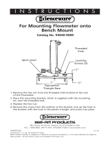
6-3.
REINSTALLATION
OF
HUB
ASSEMBLY
(Fig
ure
6-1)
If
it
becomes
necessary
to
replace
part
or
all
of
the
hub
assembly,
reinstall
the
new
hub
assembly
as
follows:
1.
Remove
hub
assembly
from
hub
support,
and
disassemble
discarding
worn
or
broken
parts.
2.
Slide
the
following
items
onto
the
hub
support
shaft
in
order
given.
a.
Spring
b.
Keyed
Washer
c.
Fiber
Washer
d.
Brake
Washer
e.
Hub
f.
Brake
Washer
g.
Fiber
Washer
3.
Align
keyway,
and
insert
hub
support
shaft
through
selected
hole
in
hub
support.
4.
Install
hex
nut
onto
hub
support
shaft.
Tighten
hex
nut
until
a
slight
drag
is
felt
while
turning
hub.
5.
Install
welding
wire
according
to
Section
3-8.
6-4.
DISPLAY
BOARD
PC4
METER
CHECK
(Fig
ure
6-2)
Check
points
are
provided
on
the
display
board
PC4
for
checking
power
supply
and
input
command
for
the
me
ters.
WARNING:
ELECTRIC
SHOCK
can
kill.
Do
not
touch
live
elect
rical
parts.
Be
sure
that
personnel
performing
testing
procedures
are
familiar
with
and
follow
stan
dard
safety
practices.
Shut
down
unit
before
making
or
changing
meter
or
test
equipment
lead
connections.
ELECTROSTATIC
DISCHARGE
(ESD)
can
damage
Circuit
boards.
Put
on
a
properly
grounded
wrist
strap
BEFORE
handling
circuit
boards.
Transport
all
static-sensitive
components
in
proper
static-shielding
carriers
and
pack
ages.
Perform
work
only
at
a
static-safe
work
area.
1.
Open
robot
interface
access
door.
2.
Locate
display
board
PC4.
3.
Check
voltage
according
to
Figure
6-2.
a
Wlre
Reel
Spring
Retaining
Ring
Wlre
Retainer
Spanner
Nut
Hub
Support
Shaft
OPTIONAL
Keyed
Washer
Brake
Washer
Hub
Fiber
Washer
Fiber
Washer
Figure
6-1.
Hub
And
Reel
Assemblies
Hub
Support
Ref
SC.127~28
OM-1
52
308
Page
9

P.
6-5.
CIRCUIT
BOARD
HANDLING
PRECAUTIONS
AA
WARNING:
ELECTRIC
SHOCK
can
kill.
Do
not
touch
live
electrical
parts.
Shut
down
unit,
welding
power
source,
and
robot,
and
disconnect
input
power
employing
lockout/tagging
procedures
before
inspect
ing,
maintaining,
or
ser..icing.
Lockoutitagging
procedures
consist
of
padlock
ing
line
disconnect
switch
in
open
position,
re
moving
fuses
from
fuse
box,
or
shutting
off
and
red-tagging
circuit
breaker
or
other
disconnect
ing
device.
a
CAUTION:
ELECTROSTATIC
DISCHARGE
(ESD)
can
damage
circuit
boards.
Put
on
properly
grounded
wrist
strap
BEFORE
handling
circuit
boards.
Transport
circuit
boards
in
proper
static-
shielding
carriers
or
packages.
Perform
work
only
at
a
static-safe
work
area.
INCORRECT
INSTALLATION
or
misaligned
plugs
can
damage
circuit
board.
Be
sure
that
plugs
are
properly
installed
and
aligned.
EXCESSIVE
PRESSURE
can
break
circuit
board.
Use
only
minimal
pressure
and
gentle
move
ment
when
disconnecting
or
connecting
board
plugs
and
removing
or
installing
board.
6-6.
TROUBLESHOOTING
J~
WARNING:
ELECTRIC
SHOCK
can
kill.
_____
Do
not
touch
live
electrical
parts.
Shut
down
unit,
welding
power
source,
and
robot,
and
disconnect
input
power
employing
lockout/tagging
procedures
before
inspecting
or
servicing.
Lockout/tagging
procedures
consist
of
pad
locking
line
disconnect
switch
in
open
position,
removing
fuses
from
fuse
box,
or
shutting
off
and
red-tagging
circuit
breaker
or
other
disconnect
ing
device.
MOVING
PARTS
can
cause
serious
injury.
Keep
away
from
moving
parts.
HOT
SURFACES
can
cause
severe
burns.
Allow
cooling
period
before
servicing.
Troubleshooting
to
be
performed
only
by
qualified
persons.
It
is
assumed
that
the
unit
was
properly
installed
accord
ing
to
Section
3
of
this
manual,
the
operator
is
familiar
with
the
function
of
controls,
the
robot
interface
was
working
properly,
and
that
the
trouble
is
not
related
to
the
welding
process.
The
following
table
is
designed
to
diagnose
and
provide
remedies
for
some
of
the
troubles
that
may
develop
in
this
robot
interface.
Use
this
table
in
conjunction
with
the
circuit
diagram
while
performing
troubleshooting
proce
dures.
If
the
trouble
is
not
remedied
after
performing
these
procedures,
contact
the
nearest
Factory
Author
ized
Service
Station.
In
all
cases
of
equipment
malfunc
tion,
strictly
follow
the
manufacturers
procedures
and
instructions.
REAR
VIEW
OF
DISPLAY
BOARD
PC4
Input
Command
For
Wire
Speed
1PM
Meter
O.8V
1PM
Input
Command
For
Volts
Meter
...O.5V
=
50V
Input
Command
For
AmmeterO.1V=
bOA
Figure
6-2.
Display
Board
Meter
Checks
Power
Supply
For
Volts
Meter
And
Ammeter
0
-
5VDC
4.
If
a
meter
power
supply
and
command
voltage
is
correct
and
the
meter
is
not
working,
replace
the
meter
(see
Section
6-5
and
contact
nearest
Fac
tory
Authorized
Service
Station).
5.
If
the
power
supply
or
command
voltage
is
incor
rect,
replace
display
board
PC4
(see
Section
6-5
and
contact
nearest
Factory
Authorized
Service
Station).
Ret.
SO-117
838-8
OM-152
308
Page
10

Table
6-1.
Troubleshooting
TROUBLE
PROBABLE
CAUSE
REMEDY
No
arc
voltage
control.
Output
control
connections.
Check
and
secure
connections
(see
Section
3-4).
Voltage
Board
PCI
not
working.
Replace
PCi
(see
Section
6-5
and
contact
near
est
Factory
Authorized
Service
Station).
Incorrect
robot
command
volt-
age.
Check
robot
command
voltage
at
Isolation
Board
P05.
Command
voltage
should
be
0-10
vdc
be
tween
pins
X
(common)
andY
at
RC17.
Wire
speed
(1PM)
meter
goes
to
zero.
Incorrect
robot
command
volt-
age.
Check
robot
command
voltage
at
Motor
Board
PC2.
Signal
should
be
0-10
vdc
between
pins
K
and
B
(common)
at
RC5.
Motor
Board
PC2
not
working.
Replace
PC2
(see
Section
6-5
and
contact
near
est
Factory
Authorized
Service
Station).
Unit
does
not
operate.
Fuse
Fl
Open.
Check
Fl
and
replace
if
necessary
(see
Section
6-2).
Correct
overload
problem
before
continu
ing
operation.
Circuit
breaker
CB1
tripped.
Check
CB1
and
reset
if
necessary
(see
Section
6-2).
Correct
overload
problem
before
continu
ing
operation.
No
meter
display.
Meter
not
working.
Use
check
points
on
Display
Board
P04
to
deter
mine
if
power
is
available
to
meter
(see
Section
6-4).
If
check
points
are
okay,
replace
meter
(see
Section
6-5
and
contact
nearest
Factory
Autho
rized
Service
Station).
Display
Board
PC4
not
working.
Use
check
points
to
determine
if
power
is
avail
able
(see
Section
6-4).
If
check
points
do
not
test
okay,
replace
P04
(see
Section
6-5
and
contact
nearest
Factory
Authorized
Service
Station).
No
wire
feed.
Robot
signal.
Check
input
signal
from
robot
to
Motor
Board
P02.
Signal
should
be
0-10
vdc
between
pins
K
and
B
(common)
on
RC5.
Relay
CR1
not
working.
Replace
CR1.
Motor
Board
P02
not
working.
Replace
PC2
(see
Section
6-5
and
contact
near
est
Factory
Authorized
Service
Station).
Wire
feeds
at
maximum
only.
Tach
board
at
wire
drive
motor
not
working.
Replace
tach
board
(see
motor/drive
assembly
Owners
Manual).
OM-152
308
Page
11

6-7.
USE
OF
INDICATOR
LIGHTS
FOR
TROUBLE
SHOOTING
£
Gas
Indicator
Light
Gas
does
not
flow
Gas
flows:
Check
gas
valve
operation.
Check
gas
valve
operation
and
gas
line
for
leaks.
Check
interface
board
PC3.
Contactor
open:
Check
interconnecting
cords.
Check
interface
board
PC3.
Wire
does
not
feed:
Check
circuit
breaker
CB1
Check
relay
CR1.
Check
interface
board
PC3.
Gas
does
not
flow
System
normal
(off).
~
Off
Contactor
open:
System
normal
(off).
Off
Wire
does
not
feed:
System
normal
(off).
On
Current
Indicator
Light
Off
Arc
started:
System
normal
(on).
No
arc:
Replace
reed
relay.
Arc
started:
Replace
reed
relay.
No
arc:
System
normal
(off).
On
Arc
Failure
Indicator
Light
Off
No
arc:
Arc
started:
Check
weld
parameters.
Check
signal
from
robot.
Signal
should
be
24
vdc
between
terminals
2TE
and
2TF.
Check
display
board
PC4.
No
arc:
Normal
during
idling.
Arc
started:
Normal
while
welding.
On
Gas
flows:
System
normal
(on.)
On
Off
Contactor
Indicator
Light~
Contactor
closed:
System
normal
(on).
On
Ir
Contactor
closed:
Check
display
board
PC4.
Wire
feeds:
System
normal
(on).
Wire
Feed
Indicator
Light
~1~
Wire
feeds:
Check
input
signal
from
robot
to
motor
board
PC2.
Signal
should
be
0-10
vdc
between
pins
K
and
B
(common)
at
RC5.
Check
motor
board
PC2
QM-152
308
Page
12

pc~6
C
U)
m
C)
0
z
-J
m
I
m
C)
-I
C)
I
D
C)
U)
CO
~.t
0
0
~
CO
iT
0
0
~
as
o
£
£
C
0000
/5
,~
/0/
dl
Circuit
Diagram
No.
SC-i
53
281-A
Diagram
7-1.
Circuit
Diagram
For
Robot
Interface

PC
6
>12
>~
>~
>6
6.QN
Circuit
Diagram
No.
SA-138
519
Diagram
7-2.
Circuit
Diagram
For
Gas/Current
Sensing
Control
55
56
12
13
1/
P07
I>
3>~
8>
A
B
C
D
E
5T
0
0 0 0
0
52
/2
69 68
3
GB
I
8L/(
52
1
_
T
A~HT
0/2>2
PEED
OM-152
308
Page
14

SECTION
8
PARTS
LIST
Cl
031692
006
426
.
C3,4
028291
CB1
011
991
CR1
109006
CR2
052
964
CR3
095 033
CR4
093
558
.
CR5,6
095521
0499700008841
079
844
027811
048
029
D1-3
026202
Fl
*012655
046 432
PB1-3
021
105
PCi
148320
073
756
110391
PC2
071
642
0943620007459
149339
089
032
1185500008052
109041
.
PLG9
047636
079 535
079 739
096813
PLG16
048598
079
534
0499890007459
PLG12
073686
039
828
600 848
604109
601
226
601
228
600
750
PLG14,63
079748
079747
PLG2O
081
379
081
378
PLG24
084198
081
378
PLG25
131
054
113746
PLG29,30
135
787
081
378
PLG61
135788
079
747
PLG62
135559
079
747
Ri
030651
1
Dia.
Mkgs.
Part
No.
Description
Quantity
1
2
2
4
4
4
3
3
PC3
PC4
PC5
Main
Assembly
.
CAPACITOR,
elctlt
750uf
200VDC
CLAMP,
capacitor
2.000dia
CAPACITOR,
cer
disc
.luf
500VDC
CIRCUIT
BREAKER,
man
reset
1
P
1
.5A
250V
RELAY,
end
24VAC
DPDT
RELAY,
end
24VDC
DPDT
RELAY,
end
24VAC
4PDT
RELAY,
end
12OVAC4PDT
RELAY,encI24VDC4PDT
BRACKET,
mtg
relay
SPRING,
hold
down
relay
SOCKET,
relay
14
pin
CLIP,
retaining
skt
relay
DIODE,
rect
1
A
400V
SP
FUSE,
mintr
cer
1OA
250V
HOLDER,
fuse
mintr
.250
x
1.250
panel
mtg
SWITCH,
PB
SPDT
CIRCUIT
CARD,
voltage
control
STAND-OFF,
No.
6-32
x
.625
Ig
7
GUIDE,
mtg
PC
card
CIRCUIT
CARD,
motor
speed
control
083
147
..
GROMMET,
scr
No.
8/10
panel
hole
.312sq
.500
high
CIRCUIT
CARD,
relay
CIRCUIT
CARD,
meter
LENS,
LED
4341
red
CIRCUIT
CARD,
isolation/amplifier
110
375
..
STAND-OFF
SUPPORT,
PC
card
No.
6
screw
CABLE,
interconnecting
(consisting
of)
HOUSING
PLUG
&
PINS,
(consisting
of)
TERMINAL,
male
1
pin
18-14
wire
CLAMP,
cable
strain
relief
sz
17
CABLE,
pwr
shld
1
8ga
15/c
(order
by
ft)
HOUSING
PLUG
&
SOCKETS,
(consisting
of)
TERMINAL,
female
1
skt
18-14
wire
.2
15
8
.14
.2
l8ft
116
35ft
44ft
CABLE,
volt
sensing
(consisting
of)
:
.
:
PLUG,
4skt97-3106A-14S-2S
CLAMP,
cable
AN-3057-6
WIRE,
lead
mot
l2ga
strd
(order
by
ft)
WIRE,
lead
i6ga
strd
(order
by
ft)
INSULATOR,
vinyl
clamp
univ
25A
CLAMP,
univ
25A
TERMINAL,
ring
tng
.500
stud
16-14
wire
HOUSING,
term
hdr
18
pin
TERMINAL,
contact
hdr
24-18
wire
HOUSING,
term
hdr
12
pin
TERMINAL,
female
lskt
22-18
wire
HOUSING,
term
hdr
6
pin
TERMINAL,
female
1
skt
22-18
wire
HOUSING
RECEPTACLE
&
SOCKETS
(consisting
of)
TERMINAL,
female
lskt
24-18
wire
HOUSING
PLUG
&
SOCKETS,
(consisting
of)
TERMINAL,
female
iskt
22-18
wire
HOUSING
PLUG
&
PINS,
(consisting
of)
TERMINAL,
contact
hdr
24-18
wire
HOUSING
PLUG
&
SOCKETS,
(consisting
of)
TERMINAL,
contact
hdr
24-18
wire
RESISTOR,
WW
fxd
25W
10
ohm
2
18
12
I
2
2
7
4
12
OM-152
308
Page
15

I
Dia.
M
kgs.
Part
No.
Description
Main
Assembly
(Continued)
Quantity
605
741
.
.
CLIP,
mtg
resistor
.312
ID
core
4
.
.
R2
030
941
..
RESISTOR,
WW
fxd
100W
5
ohm
1
030
949
.
.
HEAT
SINK,
rect
1
010
199
.
.
TUBING,
stl
.275
ID
x
.048
waIl
x
1.000
Ig
2
079 683
. .
HEAT
SINK,
resistor
056
170
. .
SHIELD,
resistor
1
010
193
.
.
TUBING,
stl
.375
OD
x
l8ga
waIl
x
.250
Ig
4
057
084
. .
BUSHING,
snap-in
nyl
.250
ID
x
.375mtg
hole
1
.
.
R3
079
497
..
RESISTOR,
WW
fxd
25W
2K
ohm
1
. .
R4
603
856
..
POTENTIOMETER,
WW
sltd
sft
biT
2W
10K
ohm
1
0937270007459
. .
BRACKET,
mtg
potentiometer
..
RC5
117
374
. .
HOUSING,
term
conn
22posn
009
335
. .
STAND-OFF,
No.
4-40
x
.625
Ig
..
RC9
047 637
..
HOUSING
RECEPTACLE
&
SOCKETS,
(consisting
of)
079 534
.
.
.
.
TERMINAL,
female
lskt
18-14
wire
..
RC12
076
624
..
RECEPTACLE,
4
pin
MS-3102A-14S-2P
..
RC13
094
480
..
RECEPTACLE,
14
pin
MS-3102A-20-27P
..
RC16
097 867
..
RECEPTACLE,
17
pin
MS-3102A-20-29P
..
RC17
094
591
..
RECEPTACLE,
24
pin
MS-3102A-24-28P
. .
Sb
011
609
..
SWITCH,
tgl
SPDT
15A
125VAC
.
.
S2
011
770
..
SWITCH,
tgl
SPDT
5A
125VAC
..
SRi
035
704
..
RECTIFIER,
integ
40A
800V
.
Ti
,3
035
759
..
TRANSFORMER,
control
mintr
115/36VCT
. .
T2
036
135
..
TRANSFORMER,
control
115/24VAC
.
.
T4
084
201
..
TRANSFORMER,
signal
16VCT
.4A
..
1T,2T
038 856
..
BLOCK,
term
20A
14P
.
.
3T
038
772
..
BLOCK,
term
20A
6P
601
219
. .
LINK,
jumper
term
blk
20A
010
916
.
.
CONNECTOR,
clamp
cable
.750
1324810008989
. .
CABINET,
control
047
838
.
.
BLANK,
snap-in
nyl
1
.000mtg
hole
107
983
. .
BLANK,
snap-in
nyl
.500mtg
hole
1124730008933
.
.
PANEL,
mtg
components
+1169690008908
. .
DOOR,
access
cabinet
045
852
.
.
CLIP,
component
.687d1a
mtg
adh
back
010
311
. .
CLAMP,
nyl
.750
clamp
dia
x
.500
wide
134
327
. .
LABEL,
warning
general
precautionary
010
855
.
.
RETAINER,
scr
No.
2
010
853
.
.
FASTENER,
scr
sltd
hd
No.
2
073
487
..
NUT,
speed
No. 2
NAMEPLATE,
(order
by
model
and
NSPR
number)
121
594
. .
CABLE,
interconnecting
(consisting
of)
094
481
.
.
. .
PLUG,
14
pin
MS-3i06A-20-27P
116
964
.
.
.
.
CLAMP,
cable
97-3057-1012
110
015
.
.
.
.
CABLE,
port
No.
187/c
(order
by
ft)
094482
.
. .
.
PLUG,
i4skt97-3106A-20-27S
045 348
. .
CABLE,
motor
(consisting
of)
047
636
..
.
.
HOUSING
PLUG
&
PINS,
(consisting
of)
079 535
TERMINAL,
male
1
pin
18-14
wire
079
739
. . .
.
CLAMP,
cable
strain
relief
sz
17
073
139
. . . .
CABLE,
port
No.
16
6/c
(order
by
ft)
071
892
. .
..
RECEPTACLE
w/SOCKETS,
(consisting
of)
079
534
TERMINAL,
female
1
skt
18-14
wire
048
144
. .
1338640009860
.
.
.
.
TERMINAL,
male
1
pin
plug
keying
CABLE,
interconnecting
(consisting
of)
097
868
. . .
.
PLUG,
l7skt
MS-3106A-20-29S
116
964
.
. .
.
CLAMP,
cable
97-3057-1012
2
120
032
. . .
.
CABLE,
port
No.
18
6/c
(order
by
ft)
I
Oft
097
866
. .
. .
PLUG,
17
pin
MS-3iO6A-20-29P
1
OM-152
308
Page
16
1
1
2
1
14
.2
.5
.2
.2
.2
.2
.2
loft
14
.2
28ff
14
/