SMC IZN10-P Series Owner's manual

Type
Owner's manual

This manual is also suitable for

- 1 -
Doc. No. IZ
※-
OML0002-C
OPERATION MANUAL
Ionizer
PRODUCT NAME
:
IZN10 Series MODEL:
Read this operation manual carefully to
understand before installation and operation.
Pay extra attention on the clause concerning the
safety.
Keep this operation manual available whenever
necessary.
INDEX
1. Safety Instructions・・・・・・・・・・・・・・・・・・・・・・・・・・ 3
2. Specifications ・・・・・・・・・・・・・・・・・・・・・・・・・・・・・・・・ 5
3. How to Order・・・・・・・・・・・・・・・・・・・・・・・・・・・・・・・・・ 6
4. Mounting
4-1. Precautions for mounting・・・・・・・・・・・・・・・・・・・・・・・・・・・ 7
4-2. How to mount・・・・・・・・・・・・・・・・・・・・・・・・・・・・・・・・・・ 9
4-3. Wiring table・・・・・・・・・・・・・・・・・・・・・・・・・・・・・・・・・・・ 15
4-4. Power supply cable wiring diagram・・・・・・・・・・・・・・・・・・・・・・ 16
4-5. Timing chart・・・・・・・・・・・・・・・・・・・・・・・・・・・・・・・・ 16
5. Functional Explanations ・・・・・・・・・・・・・・・・・・・・・・・・・・・・・・ 17
6. Outline Dimensions・・・・・・・・・・・・・・・・・・・・・・・・・・・・・・・ 18
7. Maintenance
7-1. Precautions for maintenance・・・・・・・・・・・・・・・・・・・・・・・・・・・・ 19
7-2. How to maintain electrode needle・・・・・・・・・・・・・・・・・・・・・・・・・・ 20
- 2 -
1. Safety instructions
These safety instructions are intended to prevent hazardous situations and/or equipment damage. These
instructions indicate the level of potential hazard by labels "Caution," "Warning" and "Danger" to ensure
safety. be to observe ISO4414, JIS B8370 and other safety precautions.
CAUTION Operator error could result in injury or equipment damage.
!
WARNING Operator error could result in serious injury or loss of life.
!
DANGER In extreme conditions, there is a possibility of serious injury or loss of life.
!
1) ISO 4414: Pneumatic fluid power – Recommendation for application of equipment to transmission and
control systems
2) JIS B 8370: Rule for Pneumatic System
WARNING
!
1. The compatibility of equipment is the responsibility of the person who designs the system or
decides its specifications.
Since the products specified here are used in various operating conditions, their compatibility with the
specific system must be based on specifications or analysis and/or tests to meet your specific requirements.
The expected performance and safety assurance will be the responsibility of the person who has determined
the compatibility of the system. This person should continuously review the suitability of all items specified,
referring to the latest catalog information with a view to giving due consideration to any possibility of
equipment failure when configuring a system.
2. Only trained personnel should operate machinery and equipment.
This product generates high voltage, so it can be dangerous if an operator is unfamiliar with it. Assembly,
handling or repair of systems should be performed by trained and experienced operators.
3. Do not service machinery/equipment or attempt to eliminate components until safety is
confirmed.
1) Inspection and maintenance of the machinery and equipment should be performed after confirmation of
safety such as grounding, prevention of electric shock and prevention of other types of injury.
2) When equipment is to be eliminated, confirm the safety process as mentioned above. Cut air pressure
supply and electric power supply that are the energy source for the equipment, and exhaust all residual
compressed air in the system.
3) Before machinery/equipment is re-started, take measures to prevent short circuit etc. with care.
4. Contact SMC if the product is to be used in any of the following conditions.
1) Conditions and environments beyond the given specifications, or if product is used outdoors.
2) Installation on equipment in conjunction with atomic energy, railway, air navigation, vehicles, medical
equipment, food and beverages, recreation equipment, emergency stop circuits, clutch and brake
circuits in press applications, or safety equipment.
3) An application which has the possibility of having negative effects on people, property, or animals
requiring special safety analysis.
- 3 -
- 4 -
WARNING
Selection
1. The ionizer (hereinafter referred to as the “product”) is intended to be used for the general FA devices.
!
If other applications (especially those indicated in 4 on page 2) are used, contact SMC before use.
2. Use under specified voltage and temperature.
Voltage out of specification may cause malfunction, breakage, electric shock or fire.
3. Use clean compressed air for fluid.
Do not use inflammable or explosive gas for fluid. It may cause fire or explosion. When fluid other than
compressed air is used, contact a SMC service representative.
4. The product doesn’t incorporate explosion-proof construction.
Do not use this product in a place where a dust explosion might be triggered or inflammable or explosive
gas is present. It may cause fire.
CAUTION
!
1. The product has not been washed.
Flush and confirm its purification level before bringing into a clean room.
Handling
CAUTION
!
1. Do not drop, hit or otherwise apply excessive impact (10 G or more) when handling.
Though the product itself doesn’t break, the inside construction may be broken and cause malfunction.
2. When cable is mounted or removed, pinch the modular plug claw with fingers and insert or take out the
plug vertically. If mounted or removed in an inappropriate direction, the mounting part of the modular jack
may be damaged and cause operation failure.
- 5 -
2. Specifications
Model number of ionizer IZN10-□□
(NPN)
IZN10-□□P
(PNP)
Ion generating method Corona discharge type
Voltage applying method High frequency AC type
Discharge output Note 1) 2500V
Ion balance Note 2) ±10 V at max.
Ozone generated amount Note 3) 0.03 ppm (0.05 ppm for energy saving charge
elimination nozzle
Fluid Air (clean and dry)
Operating pressure Note 4) 0.05 MPa~0.7 MPa
Air
purge
Connected tube diameter 6 and 1/4 inch
Power supply voltage 24VDC±10%
Current consumption 80 mA
(When input and output signals are not used)
Discharge stop signal
Reset signal
Input
signal External switch signal
GND to connection
The voltage to turn on is 0.6V
or less.
Current consumption: 5 mA or
less
+24V to connection
The voltage to turn on is from
+19V to the
power supply voltage.
Current consumption: 5 mA
or less
Discharge signal
Error signal
Output
signal
Maintenance signal
Max. load current: 40 mA
Residual voltage: 1 V or less
(with load current of 40 mA)
Max. applied voltage: DC 28
V
Max. load current: 40 mA
Residual voltage: 1 V or less
(with load current of 40 mA)
Effective charge eliminating distance 20~500 mm
Ambient temp.
Fluid temp.
0~55oC
Ambient humidity 35~65% RHWith no condensation
Material Body: ABS, Stainless Nozzle: Stainless
Electrode needle: Tungsten
Vibration resistance Durable to 50 Hz with amplitude 1 mm for 2 hours in
each X, Y and Z direction
Impact resistance 10 G
Weight 120 g
Applicable standard/directive
CE (EMC directive: 89/336/EEC, 92/31/EEC
93/68/EEC, 2004/108/EC, Low-voltage directive:
73/23/EEC, 93/68/EEC)
Note 1) This is the value when measured by a probe with 1,000 M and5 pF.
Note 2) This specification is applicable when the distance between the charged object and the
ionizer is 100 mm using the power saving static elimination nozzle, and the air purge
pressure is 0.3 MPa.
Note 3) This is the value from which the background is drawn with a distance of 300 mm from the
front face of the nozzle.
Note 4) Charge elimination is not available without air purge. Also, without air purge, internal
ozone concentration will increase and adversely affect the product and peripheral
equipment.
3. How to Order
IZN10 - 01 P 06 Z - B1
Service parts Option
Electrode needle assembly Manifold mounting parts set
   ・IZN10-NT Hexagon socket head bolts, spacer and hexagon nuts are included.
The ionizer and L-bracket or DIN rail mounting need to be ordered separately.
Body Assembly
Electrode needle cleaning kit/IZS30-M2
A
ccessories
Power supply cable
Cartridge Assembly    ・IZN10-CP(3m) ・IZN110-CPZ(10m)
Bracket
   ・L-bracket/IZN10-B1
   ・Swing bracket/IZN10-B2
   ・DIN rail mounting bracket/IZN10-B3
IZN10 High frequency AC nozzle type
Series name
NIL Not provided
B1 L-bracket
B2 Swing bracket
B3 DIN rail mounting bracket
Bracket
NIL NPN
PPNP
Output specification
06 f6: metric
07 f6.35
1/4"): inch
16 f6: metric (elbow)
17 f6.35
1/4"): inch (elbow)
Piping diameter
Manifold mounting parts
 ・IZN10 - ES 2
Mounting pitch
ES 17mm
Number of manifol
d
2 2 stations
3 3 stations
4 4 stations
Nozzle shape
NIL
01
02
11 Piping female Note 1) Rc1/8
Type
Energy saving charge elimination nozzle
Large flow nozzle
Power supply cable
NIL 3m
Z 10m
N Not provided
B
B
・IZN10 - A002 - 01 06
Nozzle shape
NIL
01
02
11 Piping female Note 1) Rc1/8
Large flow nozzle
Type
Energy saving charge elimination nozzle
Piping diameter
06 f6: metric
07 f6.351/4"): inch
16 f6: metric (elbow)
17 f6.351/4"): inch (elbow)
・IZN10 - A003 - P
NIL NPN
PPNP
Output specification
- 6 -
4. Mounting
4-1. Precautions for mounting
- 7 -
WARNING
Mounting
!
1. Provide required space for maintenance, wiring and piping at installation.
Install connector and One-touch fitting for air supply to allow removal and mounting of cable and tube.
Do not bend cable and tube at steep angles. Affix them straight, within the minimum bending radius to
prevent applying stress to the installation base of the connector and One-touch fitting.
Forcible installation and removal may cause malfunction, broken wires, fire or air leakage.
Minimum bending radius: Power supply cable・・・・・・・・・・・・・35 mm
Note: This is the allowable bending radius when affixing wiring at 20oC. If bending cable at lower
temperatures, excessive force may be applied to the connector even within or below the minimum
bending radius.
See instructions or catalog for minimum bending radius for tube.
2. If the product is mounted directly, mount it on a flat face.
If the mounting face has a concave, convex, distortion and/or step, excessive force is applied to the
product, which may cause damage and failure of the product. Also, dropping and other strong impact may
cause failure and accident.
3. Do not use in a place subject to noise (electromagnetic wave, surge etc.)
It may cause malfunction, or deteriorate or damage internal elements. Take measures to prevent noise
sources and prevent lines from touching and mixing together.
4. Tighten within the specified torque.
See the following table for the tightening torque. When exceeding the tightening torque, mounting screws,
mounting bracket, etc. may be broken. The screw may loosen if tightened less than prescribed torque
range.
Screw size Recommended
tightening torque
M3 0.61 to 0.63 Nm
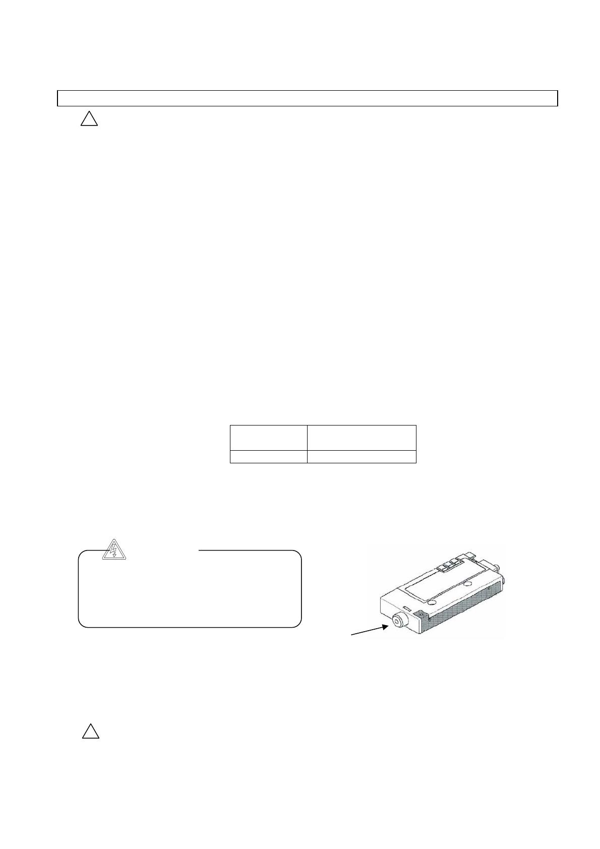
5. Do not allow foreign matter or tools to enter the nozzle.
The inside of the nozzle has electrode needles. If a metal tool makes contact with the electrode needles, it
can cause electric shock, resulting in a sudden movement by the operator that can cause further injures by
such as hitting its body to peripheral equipment. Also, if the tool damages the electrode needle, the
product may fail or cause an accident.
6. Do not attach tape or seal on the product body.
If conductive adhesive or reflective paint is contained in the tape or seal, dielectric phenomenon will occur
due to the produced ion and it may lead to electrostatic charge and electric leakage.
7. Be sure to cut off the power supply before installing and adjusting the product.
CAUTION
1. Be sure to check for proper charge elimination after mounting the product.
The charge-elimination effect largely depends on ambient mounting conditions, operating conditions, etc.
After mounting the product, check for proper charge elimination.
Particularly, if there is a wall near the product, emitted ions can not reach a charged object for effective
!
High voltage
The electrode needles are subject to high voltage.
If a foreign matter is put in the nozzle and makes
contact with them, electric shock can make a
sudden movement by the operator, which can
cause injury. Therefore, do not to touch them.
Nozzle
charge elimination, and the charge-elimination effect can decrease.
- 8 -
Wiring and piping
WARNING
!
1. Check that power supply capacity is enough and voltage meets specification before piping.
2. Always use a UL listed/recognized power supply that is a class-2 power supply with DC 24 V and under 2.1 A.
3. To keep specified performance of the product, provide class D grounding to the metal (shaded) part
around the external face of the product.
Otherwise, not only can the charge-elimination capability of the product decrease, but electric shock and
damage to the product and power supply can occur.
4. Be sure to cut off power supply before wiring (including connector plug-in/out).
5. Turn on the power after examining the wiring and surrounding situation thoroughly, and confirming safety.
6. Do not connect and disconnect connectors while supplying the power. The product may be broken and
cause malfunction.
7. Installation of a high-voltage line and the power line in the same wiring route may cause malfunction due to
noise. Install them separately.
8. Be sure there is no incorrect wiring before operation. Incorrect wiring may cause the product to break or
malfunction.
9. Flush pneumatic piping before installing. Make sure that all dust, water droplets, oil etc. are eliminated
before piping.
Operating and storage Environment
WARNING
!
1. Use within operating fluid and ambient temperature range.
Operating fluid and ambient temperature range for the product, feedback sensor and auto-balance sensor
are 0 to 50oC. Though ambient temperature is within specification, dew condensation may be generated
where temperature is suddenly changed. Therefore do not use under such conditions.
2. Do not use the product in an enclosed space.
The product utilizes a corona discharge and generates a slight amount of ozone and NOx.
If it is used in a closed space, ozone is concentrated so much as to possibly affect human body. Therefore,
it is necessary to set up a ventilation system in the space. Also, even with ventilation, the use of plural
ionizers in a narrow space can increase the concentration of ozone, and so it should be noted that the
ozone concentration must be 0.1ppm or less, which is a standard value for working place.
3. Take prevention measures against ozone.
Equipment used around the product should have ozone-prevention measures.
Also, check regularly that nearby equipment will not be affected adversely by exposure to ozone.
4. Environment to avoid
Do not use or store under the following environments, as these may cause operation failure. If it is
unavoidable, take the appropriate measures.
- 9 -
a. Where ambient temperature exceeds 0 to 50oC.
b. Where ambient humidity exceeds 35 to 65% RH.
c. Where dew condensation is generated due to sudden temperature change.
d. Where there is corrosive gas, inflammable gas, or where volatile inflammable substances are stored.
e. Where the product is exposed to conductive powder such as iron powder and dust, oil mist, salt and
organic solvent or machining chips, particles and cutting oil (water, liquid).
f. Where the product is directly exposed to the blow from air-conditioners.
g. Where seals and ventilation is not installed.
h. Where the product is exposed to direct sunlight and radiant heat.
i. Where strong electromagnetic noise is generated. (Strong electric field/strong magnetic field/surge.)
j. Where electricity is discharged on the product.
k. Where a strong high frequency is generated.
l. Where lightning disaster is expected.
m. Where the product is directly exposed to vibration and impact.
n. Where force or weight that causes deformity to the product is applied.
5. Do not use air containing mist or dust.
Air containing mist or dust may lower the function and shorten the maintenance cycle. A dryer (IDF series),
air filter (AF/AFF series) and mist separator (AFM/AM series) can be used to produce clean compressed
air.
6. The product does not incorporate a protection to lightning surges.
7. The product can not be used without air purge.
Without air purge, not only is the charge elimination not available, but also internal ozone concentration
will increase and adversely affect the product and peripheral equipment. Therefore, be sure to perform air
purge when energizing the product.
4-2.How to mount
Investigate the area generating static electricity, or the process or part emitting electrostatic interference
preliminarily, and check the conditions under which effective charge elimination can be performed before
mounting the product.
4-2-1 Grounding
Provide class D grounding to the external face of the body or metal part of the bracket. Without grounding,
charge elimination capability decreases, the ion balance breaks and electric shock and damage to the
product and power supply may occur. Also, if the grounding is provided improperly, a maintenance alarm
is outputted.
If the mounting area for the product is not provided with class D grounding, use a grounding tap for wiring.
4-2-2 Mounting
When mounting the product, use a M3 hexagon socket head bolts. Tightening torque is 0.61 to 0.63 Nm.
1) Body mounting tap or through hole
Referring to the figure below, affix the product using hexagon socket head bolts with optimum length.
- 10 -
Use a bolt with a length of 12 mm or more.
Use a bolt with a max. screw-in depth of 10
mm or less
10mm or less
Body tap Through hole
2) L-bracket
The L-bracket can be mounted in 4 different ways as shown below.
Outward mounting Inward mounting
Swing mounting
Fixed mounting
Outward mounting of L-bracket
1. Prepare hexagon socket head bolts (M3 X 6) and washers attached to the product and mount the
L-bracket.
2. Adjust the product to the desired mounting angle referring to figure 3 and fix it. For the oval hole, use the
washer attached to the product. Hexagon socket head bolts are not included and need to be prepared
separately.
3. The mounting angle of the product can be adjusted in the following range.
Avoid interfering with piping.
- 11 -
Inward mounting of L-bracket
1. Before mounting the product, mount the L-bracket where the product will be installed. The mounting
angle of the bracket can be adjusted in the following range. Hexagon socket head bolts are not included
with the product and need to be prepared separately.
2. Affix the product with the hexagon socket head bolts (M3 X 6) and washers attached to the product.
Tightening torque is 0.61 to 0.63 Nm.
3) Swing bracket
1. Mount a swing bracket to the product with the hexagon socket head bolts and washers attached to the
product. Tightening torque is 0.61 to 0.63 Nm.
2. Adjust the product to the desired mounting angle and fix it.
90°
- 12 -
4) DIN rail mounting bracket
1. Adjust the L-bracket to the desired angle and fix it.
2. Mount the L-bracket to the product with the hexagon socket head bolts (M3 X 6) and washers attached
to the product.
3. Mount the product to the DIN rail and tighten the socket head bolts to fix it.
Fixing hexagon socket head bolt
- 13 -
5) Mounting
1. Insert the spacers between the counter bores of the body.
2. Hold the product by L-brackets from both ends and tighten the hexagon socket head bolts. Tightening
torque is 0.61 to 0.63Nm.
The composition of parts to connect 3 ionizers is shown below.
- 14 -
Fixing hexagon socket head bolt M3
L-bracket
DIN rail mounting bracket
Spacer
Hexagon nut M3
4-3.Wiring table
Cable color
Necessity
of wiring
Signal name I/O Specification
No.
- 15 -
1 Brown
Power
supply +24
V
2 Blue
Power
supply GND
3 Orange
Discharge
stop signal Input When the signal is turned off, discharge stops.
When the signal is turned on and then off, the
error signal is reset.
4 Pink Reset signal Input When the signal is turned off: Continues
normal operation.
5 White
Discharging
signal Output The signal holds ON during discharge
The signal is turned off when error happens.
6 Purple Error signal Output
7 Yellow
Maintenance
signal Output The signal is turned on when maintenance is
due.
8 Gray
External switch
signal 1 Input When the signal is turned on, discharge stops.
Light
blue
External switch
signal 2
9 Input When the signal is turned on, discharge stops.
.Necessity of wiring
: Wiring necessary to operate the product
In addition to the above wiring, provide class D grounding to the metal (shaded) part around the external
face of the product. If the grounding is not provided or is provided improperly, specified charge elimination
capability is not available. Also, the maintenance signal is turned on.
Input signal
NPN: The signal is turned on when the product is connected with the power supply GND, and turned off when
disconnected.
PNP: The signal is turned on when the product is connected with the 24 V power supply, and turned off when
disconnected.
Output signal
NPN: Signal ON when a output transistor is energized (with the power supply GND at the inside of the
product) and OFF when de-energized.
PNP: Signal ON when a output transistor is energized (with the 24 V power supply at the inside of the
product) and OFF when de-energized.
4-4. Power supply cable wiring diagram
- 16 -
+ Power supply    
GND DC24V±10%
Brown +24V
Blue GND
INPUT
+24V
PLC
Orange Discharge stop signal
Pink Reset signal
or
or
Ionizer
OUTPUT INPUT
White Discharging signal
Yellow Maintenance signal
Purple Error signal
OUTPUT
OUTPUT
or
or
INPUT
Class D grounding of external metal parts
(No electricity conduction to internal circuit
Internal circuit
■ NPN
Gray External switch signal
Light blue External switch signal
+ Power supply  
GND DC24V±10%
Brown +24V
Blue GND
INPUT
+24V
PLC
Ionizer
OUTPUT
INPUT
OUTPUT
or
or
OUTPUT
INPUT
Internal circuit
+24V
+24V
+24V
or
or
Orange Discharge stop signal
Pink Reset signal
White Discharging signal
Yellow Maintenance signal
Purple Error signal
Class D grounding of external metal parts
(No electricity conduction to internal circuit)
Gray External switch signal
Light blue External switch signal
■ PNP
4-5. Timing chart
Timing chart
Remarks
The discharge of ion is started
when a static elimination stop
signal is turned on
Power supply on
High voltage error
Maintenance required period
The error signal can be
reset by turning on and
off the reset signal.
External switch signal on
Error signal
Maintenance signal
External switch signal 1,2
Ion is emitted even while
the maintenance signal is
on.
The signal is turned off
when error occurs.
Output
Output
Input
Power supply
Discharge stop signal
Reset signal
Discharging signal
(ON The signal turns on when
ion is discharged)
Input
Input
Input
Output
ON
OFF
Clean electrode
needles with the
p
ower su
pp
l
y
off
ON
OFF
ON
OFF
ON
OFF
ON
OFF
ON
OFF
ON
OFF
Maintenance re
q
uired
Error occurred
5. Functional Explanation
1. Detection of dirt on electrode needle
During operation reduced charge elimination capability due to a dirt or wear on electrode needles is
monitored continuously. If it becomes necessary to clean the electrode needle, the LED for maintenance
lights up on the display of the product and maintenance output signal is generated.
2. Input of external switch signal
There are two ports for external switch signal inputs.
If a pressure switch or electrostatic sensor is connected, discharge can be stopped for abnormal pressure
or completion of charge elimination.
3. Name of indication LEDs.
- 17 -
PWR ION HV NDL
Air purge
Name Indication Color Content
Power supply PWR Green Lights up when the power supply is turned on.
Discharge ION Green Lights up when discharge is performed.
High voltage error HV Red Lights up when excessive current flows to the electrode needle.
Maintenance NDL Orange Lights up when a dirt or wear on the electrode needle is detected.
(b) LED state
Item PWR ION HV NDL Remarks
Normal operation (turning on of
discharge stop signal) Ion emission
Normal operation (turning off of
discharge stop signal) Discharge stop
Detection of high voltage error
Discharge stop due to
error detection
External switch signal 1
External switch signal 2
Discharge stop due to
signal input
Ion emitted continuously
even dirt on needle is
detected
Detection of dirt on electrode needle
4. Content of alarm
Description Content How to reset
High voltage error Informs that abnormal current such as high
voltage leakage has occurred. “HV” LED
lights up and ion emission is stopped.
Turn off the power supply, solve the
error and restart the power supply.
If the error is solved correctly, turn the
reset signal on and off.
The error signal is turned off when error
occurs.
Electrode needle
maintenance
period
Informs that maintenance of electrode
needles is necessary. “NDL” LED lights up
and maintenance signal is outputted.
Turn off the power supply, clean the
electrode needle, and then restart the
power supply.
6. Outline Dimensions
IZN10-01 / IZN10-02
Energy-saving nozzle / Large-flow nozzle
- 18 -
7. Maintenance
7-1. Precautions for maintenance
- 19 -
Maintenance
WARNING
!
A high voltage generating circuit is
installed. Be sure to stop the supply
voltage at the maintenance. Do not
disassemble / renovate the product as
it may deteriorate the functions and
cause risks due to electric shock and
electric leakage.
Caution
for
High
Voltage
1. Keep electrode needle clean with regular maintenance.
Make sure that the product is operating without any failure with regular
maintenance. Only those with proper knowledge and experience should
perform maintenance on the equipment.
Dust attached on the electrode needles due to long operating lowers the
ability to eliminate static electricity. If electrode needle does not recover
its ability to eliminate static electricity after cleaning,
replace it with the new one. In order to maintain stable performance,
regular maintenance and cleaning of electrode needles are recommended.
2. The tube and fitting must be handled as a consumable part.
The tube and fitting that are connected to the female threads of piping of the product can deteriorate due
to ozone and need to be replaced regularly.
3. Stop supplying power to the body without fail when cleaning the electrode needles or exchanging the
electrode cartridge. Do not touch the electrode needles while energizing, or it may cause electric shock or
accident.
4. Do not open the case to disassemble or reconstruct the product.
It may cause electric shock, operation failure and disaster such as fire. In addition, note that if the product
is disassembled or reconstructed it may no longer perform according to specifications and will not be
covered by guarantee.
5. Do not operate the product with the wet hands.
It may cause electric shock or accident.
7-2. How to maintain electrode needles
7-2-1. Cleaning of electrode needles
1) Disconnect the power supply cable.
2) Rotate the locked knob and pull down the cartridge.
3) Clean electrode needles.
4) Mount the cartridge and power supply cable in the reverse order to complete the cleaning.
- 20 -
Switch for locking Cartridge
7-2-2 Replacement of electrode needle
1) Remove the cartridge in the same manner as 3-1.
2) Remove the electrode needle assembly and replace it with a new electrode needle assembly.
The electrode needle assembly can be removed easily from its cartridge by pulling it foreword.
At that time, pay attention to the sharp end of the needles.
CAUTION
!
Do not turn the switch for locking without the cartridge. Not only the tooth for locking can be broken, but also
the cartridge cannot be mounted due to interference with the tooth for locking.
Tooth for locking
  • Page 1 1
  • Page 2 2
  • Page 3 3
  • Page 4 4
  • Page 5 5
  • Page 6 6
  • Page 7 7
  • Page 8 8
  • Page 9 9
  • Page 10 10
  • Page 11 11
  • Page 12 12
  • Page 13 13
  • Page 14 14
  • Page 15 15
  • Page 16 16
  • Page 17 17
  • Page 18 18
  • Page 19 19
  • Page 20 20

SMC IZN10-P Series Owner's manual

Type
Owner's manual
This manual is also suitable for

Ask a question and I''ll find the answer in the document

Finding information in a document is now easier with AI