PATHLIGHT
LED LUMINAIRE SSL1, ISL1, ISL2 & BOLLARDS
Luminaires require factory-supplied
24-Volt DC power supply, specied
separately. Integral and remote
mounted power supply options
available. Secondary run lengths
dependant of selected power supply.
Fixtures supplied with 6” lead of 18
gauge wire.
This product must be installed in
accordance with applicable electrical
and installation codes by a person
familiar with the construction and
operation of the product and the
hazards involved. “CAUTION– RISK OF
FIRE”
INSTALLATION
Before beginning any pathlight
installation, disconnect electrical power
at main switch or circuit breaker.
To reduce the risk of re, electric shock,
and potential damage to recessed
housing assembly when electrical power
is re-connected, DO NOT ATTEMPT TO
CONNECT the following on branch circuit
serving pathlight assembly:
CAUTION
•Motors •Power tools •Extension cords
•Appliances or similar electronics
A.
Fixtures to be mounted in conditions where
ambient temperatures do not exceed 40°C.
Ensure AC input voltage is protected against
surges & load shifts prior to power supply
input.
SAFETY INSTRUCTIONSB.
Read installation instructions
completely before attempting
installation.
Failure to follow instructions may
result in improper installation and
void warranty.
Contact Lucifer Lighting Company
with any questions or concerns
before beginning any installation.
Ensure qualied electrician will
perform all electrical procedures.
Disconnect electrical power
circuit before attempting to install
pathlight or power supply.
1
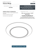
Pathlights are Class II LED luminaires
for discreet path lighting for
residential, commercial and hospitality
applications. Durable precision milled
316 stainless steel or brass casting.
C.
E.
DESCRIPTION
POWER
Optimum 18” (457mm) above walking
surface; 36” (915mm) on-center
spacing for SSL1 & ISL1; 60” (1524mm)
on-center spacing for ISL2 .
D. RECOMMENDED SPACING
1.
2.
3.
4.
5.

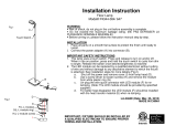
F. POWER SUPPLIES
Class 2 remote power supplies accommodate varying quantities of xtures. Power
supply must be located in a readily accessible location for future servicing.
1. REMOTE POWER SUPPLIES
REMOTE POWER SUPPLY OPTIONS
PART # Part ID
PSA-24V-60-XAT2 A
PSA-24V-XX-XXXX B
UBB-JCT-24V-60-XAT2-XXX C
A
Class
2 power supply
dimmable via 0-10V analog, reverse phase or forward phase.
Domestic version features 1/2” knockouts.
Class
2 power supply
and multiple driver options. Domestic version features 1/2”
knockouts.
Universal back box with 1/2” knockouts
, wet and concrete pour rated.
Dimmable via
0-10V analog, reverse phase or forward phase. Can be mounted using specied hanger
bars or brackets. Available for domestic and international.
B
C
3.00”(76mm)
10.5”(267mm)
4.00”(101mm)
4.700
119.37
4.700
119.38
4.70”
(119mm)
4.70”
(119mm)
2.30”(58mm)
10.5”
(227mm)
2.00”(51mm)
5.38”
(137mm)
2
1.50”
(38mm)
4.80”
(122mm)
0.80”(20mm)
1.60”
(41mm)
8.30”
(210mm)
1.30”(34mm)
Domestic International
Domestic International

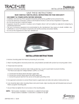
When specied with integral power supply, universal back box or Bollard feature
mounting for 1 xture. Universal back box power supply can support multiple
xtures. Separate mounting components required for each xtures.
2. INTEGRAL POWER SUPPLY
3
2.9”(74mm)
luminaire
centerline

Specied collar
length
G. LUMINAIRE MOUNTING OPTIONS
SSL-UMP: Compatible with two-gang switch box or 4-square junction box for Dry
/ Damp locations and weatherproof single or two gang box for Wet and concrete
pour locations. Must use provided gasket in Wet locations.
SSL-MP-(Collar Length): For use with single gang weatherproof box for Wet and
concrete pour locations. Must use provided gasket in Wet locations.
1. MOUNTING PLATES - DRY / DAMP, WET AND CONCRETE POUR LOCATIONS
0.63”(16mm)
SSL-UMP
SSL-MP-(Collar Length)
Secure mounting
plate to customer
furnished back box
Collar to nish
ush with nished
substrate
Specied collar
length
SSL-BB
0.63”
(16mm)
SSL-BB: Includes back box, gasket and SSL-UMP mounting plate; features 1/2”
knockouts on top, bottom and back of box.
SSL-BB-(Collar Length): Includes back box, gasket and mounting plate with
specied collar length; features 1/2” knockouts on top, bottom and back of box.
Note: All unused knockout must be sealed with supplied plugs.
2. BACK BOXES - DRY / DAMP, WET AND CONCRETE POUR LOCATIONS
Collar to nish
ush with nished
substrate
SSL-BB-(Collar Length)
4
Ensure mounting component and wiring is in place before installing substrate.
Minimal tolerances exist between xture and mounting component, cutout
dimensions are critical. Part numbers & Images depicted through this guide are
applicable of SSL1 & ISL1.
SSL1 & ISL1: 2.40” (62mm)
square cutout
ISL2: 2.40” (62mm) H X
4.10” (104mm) W cutout
SSL1 & ISL1: 2.40” (62mm)
square cutout
ISL2: 2.40” (62mm) H X
4.10” (104mm) W cutout
Gasket
Gasket

1.00”
(25mm)
SSL-RM: Remodel collar for installing xture into drywall / plasterboard.
SSL-CC: Cavity collar for installing xture into cavity or bore.
SSL-SC3: Stud-mount collar, adjusts from 1/2” to 3”. Features 1/2” knockouts.
SSL-SC6: Stud-mount collar, adjusts from 3” to 6”. Features 1/2” knockouts.
3. MOUNTING COLLARS - DRY / DAMP LOCATIONS ONLY
SSL-RM
SSL-CC
0.69”(18mm)
SSL-SC3
SSL-SC6
Insert collar into cutout ush with
nished substrate; fold tabs over
to secure
Insert collar into cutout ush
with nished substrate; secure
with customer furnished screws
or nails or suitable bonding
adhesive.
2.40” (62mm)
square cutout
Extend collar
to be ush
with nished
substrate
Secure collar to
stud with customer
furnished screws
SSL1 & ISL1: 2.40” (62mm)
square cutout
ISL2: 2.40” (62mm) H X
4.10” (104mm) W cutout
SSL1 & ISL1: 2.40” (62mm)
square cutout
ISL2: 2.40” (62mm) H X
4.10” (104mm) W cutout
5

6
SSL-SMB-(Finish): Provides ush mount of luminaire. Receives secondary wiring
through back of box only.
4. SURFACE MOUNT BOX - DRY / DAMP AND WET LOCATIONS
SSL-SMB-(Finish)
Mount to nished surface through back
of box with customer furnished screws
2.45”
(62mm)
3.00”
(76mm)
10.5”
(267mm)
4.00”
(101mm)
10.5”
(267mm)
4.00”
(101mm)
Can be specied with integral or remote power supply, supplied with hanger bars
or brackets, specied on order. SSL1 & ISL1 mount horizontally or vertically, ISL2
mounts horizontally only. SSL1 & ISL1: 2.40” (62mm) square cutout. ISL2: 2.40” (62mm) H
X 4.10” (104mm) W cutout.
5. UNIVERSAL BACK BOX - WET AND CONCRETE POUR LOCATIONS
1.00”(25mm)
Hanger bars adjust from 14”
(356mm) to 24” (610mm) and may
be cut to accommodate narrow stud
spacing
Brackets, universal stainless
steel mounting ange
1.00”(25mm)
Collar to nish ush with
nished substrate.
Collar
Collar
Collar to nish ush with
nished substrate

7
BOLT-DOWN
0.88”(22mm)
KOs for wiring
Base is bolted directly to mounting
surface with customer-furnished
hardware
Four 0.28”(7mm)
bolt holes
Secure bollard to base
with supplied screws
CONCRETE POUR
0.88”(22mm)
KOs for wiring
Zinc-plate J-bolts for concrete
pour mounting
Concrete Pour
Secure bollard to base
with supplied screws
4.00”
(102mm)
Freestanding mount, receives luminaire for ush installation, available with
integral or remote power supply. Mounting option specied on order. Ensure all
wiring is installed prior to bollard installation.
6. BOLLARD - DRY / DAMP AND WET LOCATIONS
STAKE DOWN
0.88”(22mm)
KOs for wiring
Secure bollard to base
and insert into ground
14.0”
(356mm)

H. WIRING
Access wiring compartment by removing lid and lid retaining screws. Insert line,
load and control voltage wires with appropriate conduit or strain relief ttings
through knockouts.
Connect primary and control wiring to power supply. Run secondary low voltage
wiring to each xture location in either home run or parallel method.
Home Run
Parallel
Back boxes used as example of mounting location
At each mounting location, connect low voltage wiring to factory supplied 6” lead
wire with connector for attaching to xture. See next section for mounting options.
Factory supplied
lead wires
Low voltage
wiring
8
Note: Max run distance for each secondary low
voltage wiring circuit is 40 feet.
Note: Max run distance for entire secondary low
voltage wiring circuit is 40 feet.

9
I. LUMINAIRE INSTALLATION
Place self-adhesive gasket on back of luminaire for wet locations. Connect pin
connector of pathlight to lead wire connector supplied by factory (see wiring on
page 8).
Note: Gasket not used on Bollard or Surface Mount Box
Push wires into cavity / junction box and insert xture as shown below, applying
even pressure to face of xture.
Note: If mounting device collar is not ush with substrate, springs may not fully
engage.
Fixtures designated as Locking (Wet location) feature two discreet factory supplied
locking screws. While xture is pressed in place, tighten hex screws with provided
hex key.
Spring
Gasket
(Adhesive Side)

J. SERVICING LED
If Locking (Wet location) version, loosen 2 screws located inside xture aperture
using hex key. Pull xture outward from mounting surface. A small depression is
provided on the lower backside of the tting face to aid in leveraging the xture if
necessary. Disconnect pin connector and remove gasket.
Gasket
Remove 3 hex screws and separate LED assembly from xture. Replace with OEM
LED assembly sourced through Lucifer Lighting. Ensure O-ring seats properly and
screws are tightened. Replace gasket, connect pin connector and push xture into
mounting location. If Locking (Wet location), tighten 2 screws located inside xture
aperture.
Gasket
Depression
10
O-Ring

SERVICING UBBK.
STEP 1
Remove xture from UBB, see Section I.
STEP 2
Insert a athead screwdriver
through the brackets on the wiring
compartment access panel and pry
it towards the driver assembly and
remove it through the aperture (
Fig.1
).
STEP 3
Disconnect line/mains and control
wiring.
STEP 4
Loosen driver retaining nut, ensuring it
is not removed (
Fig.2
).
STEP 5
Remove driver assembly.
STEP 6
Disconnect additional load wiring if
applicable.
STEP 7
Reattach structure wiring to new
driver, as applies.
STEP 8
Install driver assembly, note that it
must be seated on the rear stud and
under the nut (
Fig.2
).
STEP 9
Secure driver retaining nut (
Fig.2
).
STEP 10
Reattach line/mains and control
wiring.
STEP 11
Install the wiring compartment access
panel (
Fig.3
).
STEP 12
Re-install xture in UBB, see Section I.
Retaining Nut Rear Stud
Wiring Compartment Access Panel
Brackets
Fig.1
Fig.2
Fig.3
Wiring Compartment Access Panel
11
*Rear stud is not visible through aperture

SERVICING PS-RMTL.
STEP 1
STEP 2
STEP 3
With lid removed, disconnect line/mains,
load and control wiring from driver.
Remove power supply retaining clamps/
screws/nuts as apply.
STEP 4
Remove and replace driver assembly
(
Fig.5).
STEP 5
Secure with retaining clamps/screws/
nuts.
STEP 6
Reattach lines/mains, load and control
wiring with suitable connectors. See
Section M.
STEP 7
Re-install lid on enclosure (
Fig.4).
Fig.4
Remove screws securing lid to enclosure
(
Fig.4).
Fig.5
12

13
DRIVER WIRING DETAILM.
“AT2” Reverse Phase Driver
“L22” Lutron Hi-Lume A Series
Forward
Phase Control Driver
Lucifer Lighting Power Supply
120-Volt
Reverse / Forward
Phase Dimmer
Hot / Black
Neutral / White
Ground
Black (-)
Red (+)
LED
Light
Engine
Black (-)
Red (+)
LED
Light
Engine
Wiring Supplied
by Others
“LP1” Lutron H Series
EcoSystem
Driver (not
available for
export)
“ED3” eldo
LINEARdrive
DALI Driver
Lucifer Lighting
Power Supply
Purple
Purple
Ground
Hot /
Black
Neutral /
White
To
EcoSystem
Digital Link
Or
DALI Digital Bus
Black (-)
Red (+)
LED
Light
Engine
Wiring Supplied
by Others
“AT2” 0-10 Volt
Driver
Lucifer Lighting
Power Supply
Purple (+)
Purple(-)
Ground
Hot /
Black
Neutral /
White
0-10 Volt Dimmer
Consult Approved Dimmer
List to Ensure Compatibility.
Install in accordance with
dimmer manufacturer’s
installation guidelines.
NOTE: Control must switch
primary for full off.
Black (-)
Red (+)
LED
Light
Engine
Wiring Supplied
by Others
“EX2” eldo
LINEARdrive
DMX Driver
Lucifer Lighting
Power Supply
Orange /
White
Orange
Ground
Hot /
Black
Neutral /
White
To
DMX Digital Bus
Brown

14
LIMITED WARRANTY
3750 IH 35 North
San Antonio, Texas 78219 USA
[PH] +1 210 227 7329
[FAX] +1 210 227 4967
www.luciferlighting.com
©2019 Lucifer Lighting Company
As part of its policy of continuous research
and product development, the Company
reserves the right to change or withdraw
specications without prior notice.
[061419]
LUCIFER LIGHTING COMPANY (Seller) warrants that for a period of one (1) year from date of sale
to the rst non-retail purchaser, Seller will repair or replace, at the Seller’s sole option, free of
charge, any defective products purchased from Seller provided that prior authorization is obtained
from the Seller and the products are sent prepaid to the Seller’s manufacturing facility. Lamps are
not warranted or guaranteed in any manner for any length of time, except LED lamp modules and
power supplies used in Seller’s recessed, surface mount and exterior lighting xtures, are war-
ranted to operate with 70% lumen maintenance from the date of sale by Seller for ve (5) years.
LED MR-16 style lamps supplied by Seller are only warranted as provided by their original maker.
Please refer to the following limiting conditions.
Where Seller’s xtures are used in conjunction with drivers/power supplies sourced by others and/or where POE (power
over ethernet) systems are present, Seller’s warranty will only apply to the Seller supplied lighting xtures. In all instances
where drivers/power supplies and/or POE are by others, the responsibility to conrm the selected power supply(s)
conforms to operating parameters of Seller’s xtures shall be the responsibility of others. Approved parameters (involving
voltage, current, and power quality for the selected xtures and outputs) will be provided by Seller upon request, however
the parameters should not be considered exhaustive for the purpose of the warranty and represents a good faith effort
by Seller to support its customers. All warranty claims are subject to Seller’s review and if Seller determines the root
cause of the issue involves supplied power supply(s) by others, Seller’s warranty shall not be applicable. Further, in such
events of supplied power supply(s) by others, Seller makes no guarantee as to xture operating performance (startup
time, icker, shimmer, pop-on/pop-off, dimming, etc.). In no event shall Seller’s obligations under this warranty extend
beyond the initial cost of the products and, accordingly, consequential damages arising out of any claimed product defect
are expressly excluded. This Warranty does not cover the costs, if any, in re-installation of products serviced under this
Warranty. This Warranty does not cover damage or failure caused by acts of God, abuse, misuse, abnormal usage, or use
in violation of any applicable standard, code or instructions for use in installations including those contained in the latest
National Electrical Code (NEC), the standards for safety of Underwriters Laboratory, Inc. (UL), standards for the American
National Standards Institute (ANSI) or, in Canada, the Canadian Standards Association (CSA), or, in the European Union,
the Conformité Européenne (CE Marking), faulty installation, or any repairs or modications other than those made by the
Seller. This Warranty does not cover damage or failure caused by abnormal spikes in power, dirty power, and light xtures
used with power supplies or other products not supplied by Seller, nor shall it apply to defects for which written notice
thereof is not received by Seller.
In the event that any of the terms of this Warranty are in conict with any rule of law or statutory provision or otherwise
unenforceable under the laws or regulations of any government or subdivision thereof, such terms shall be deemed stricken
from this Warranty, but such invalidity or unenforceability shall not invalidate any of the other terms of this Warranty and
this Warranty shall continue in force.
EXCEPT AS TO SELLER’S WARRANTY OF REPAIR OR REPLACEMENT SET FORTH ABOVE, THERE ARE NO
UNDERSTANDINGS, AGREEMENTS, REPRESENTATIONS, OR WARRANTIES, EXPRESS OR IMPLIED (INCLUDING ANY
REGARDING THE MERCHANTABILITY OR FITNESS FOR A PARTICULAR PURPOSE, AND NON-INFRINGEMENT, AND ANY
WARRANTIES ARISING FROM A COURSE OF DEALING, USAGE, OR TRADE PRACTICE), RESPECTING LUCIFER LIGHTING
COMPANY PRODUCTS. THIS WARRANTY IS THE PURCHASER’S SOLE AND EXCLUSIVE REMEDY AGAINST THE SELLER
FOR THE REPAIR OR REPLACEMENT AT SELLER’S OPTION OF DEFECTIVE LUCIFER LIGHTING PRODUCTS. UNDER NO
CIRCUMSTANCES SHALL SELLER BE LIABLE FOR ANY LOSS OR DAMAGE, DIRECT OR CONSEQUENTIAL, ARISING OUT OF
THE USE OF, OR INABILITY TO USE, THE PRODUCTS SOLD HEREUNDER.
For service under this warranty, please provide the original date of sale and nature of difculty being experienced. All
service matters should be directed to:
The Citizen, Bridgelux, Xicato, Sharp and Lumenetix LED lamp modules provided by Seller are
only suitable for use in ceiling or plenum conditions where the maximum operating temperature
of the module does not exceed 90°C (194°F) and/or the ambient temperature does not exceed 40°C
(104°F) or lower threshold as featured on Seller’s product specication literature.
These terms only cover the power supply (if purchased from Seller) and Citizen, Bridgelux, Xicato,
Sharp, and Lumenetix LED modules.
If installed outdoors, the power supply must always be shielded from direct sunlight. The power
supply cannot be installed in areas where liquids may pool.
The end user must ensure that the AC input voltage has measures in place to prevent lightning
strike surges and that large load shift surges are reduced or eliminated prior to the input of the
power supply. Power supplies returned with this type of damage are not covered under Seller’s
Limited Warranty.
Seller reserves the right to physically evaluate the LED module and driver supplied by Seller for
compliance with these conditions. An end user’s refusal to return such xture articles shall void
Seller’s Limited Warranty.
The LED module will be considered in working condition and therefore not warrantable if it meets
or exceeds 70% of its original ux and remains within a range of 3 duv.
The color temperature of the Citizen, Bridgelux, Xicato, Sharp and Lumenetix LED module is
guaranteed to remain within a range of 3 duv for a period of ve (5) years from date of sale by Seller.
Any tampering or disassembly of the LED module or LED heat-sink assembly without Seller’s prior
written consent will immediately void the warranty.
1.
2.
3.
4.
5.
6.
7.
8.
/