Dell EqualLogic PS Series iSCSI Storage Arrays Owner's manual
- Type
- Owner's manual

Dell™ PowerEdge™ Cluster
Systems
Using Dell Blade Servers
in a Dell PowerEdge High
Availability Cluster
book.book Page 1 Monday, April 19, 2010 5:06 PM

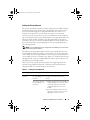
Notes and Cautions
NOTE: A NOTE indicates important information that helps you make better use of
your computer.
CAUTION: A CAUTION indicates potential damage to hardware or loss of data if
instructions are not followed.
____________________
Information in this document is subject to change without notice.
© 2007–2010 Dell Inc. All rights reserved.
Reproduction of these materials in any manner whatsoever without the written permission of Dell Inc.
is strictly forbidden.
Trademarks used in this text: Dell, the DELL logo, PowerEdge, PowerVault, EqualLogic, and
OpenManage are trademarks of Dell Inc.; EMC is the registered trademark of EMC Corporation;
Microsoft, Windows, and Windows Server are either trademarks or registered trademarks of Microsoft
Corporation in the United States and/or other countries.
Other trademarks and trade names may be used in this document to refer to either the entities claiming
the marks and names or their products. Dell Inc. disclaims any proprietary interest in trademarks and
trade names other than its own.
April 2010 Rev. A01
book.book Page 2 Monday, April 19, 2010 5:06 PM

Contents 3
Contents
1 Introduction . . . . . . . . . . . . . . . . . . . . . . . . 5
Overview . . . . . . . . . . . . . . . . . . . . . . . . . . 5
Supported PowerEdge Blade Server
Cluster Components
. . . . . . . . . . . . . . . . . . . . 6
PowerEdge Server Enclosure
. . . . . . . . . . . . 6
Supported Cluster Configurations
. . . . . . . . . . . . 16
Direct-Attached Cluster
. . . . . . . . . . . . . . 16
Switch-Attached Cluster
. . . . . . . . . . . . . . 17
Blade Server Requirements
. . . . . . . . . . . . . . . 20
Cluster Nodes
. . . . . . . . . . . . . . . . . . . . 21
Cluster Storage
. . . . . . . . . . . . . . . . . . . 22
Other Documents You May Need
. . . . . . . . . . . . 23
2 Cabling Your Blade Cluster
Hardware
. . . . . . . . . . . . . . . . . . . . . . . . 25
Cabling Your Cluster For Public and
Private Networks . . . . . . . . . . . . . . . . . . . . 25
Cabling the Private Network
. . . . . . . . . . . . 27
Cabling the Public Network . . . . . . . . . . . . 28
Cabling the Storage Systems
. . . . . . . . . . . . . . 29
Direct-Attached Cluster
. . . . . . . . . . . . . . 29
Network-Attached Cluster
. . . . . . . . . . . . . 32
book.book Page 3 Monday, April 19, 2010 5:06 PM


Introduction 5
1
Introduction
This document provides information for installing and managing your
Dell™ PowerEdge™ blade server in a Dell PowerEdge cluster system and
specific information about clustering your PowerEdge blade server modules
with supported Dell PowerVault™, Dell EqualLogic™, and Dell/EMC storage
systems. Use this document in conjunction with the Installation and
Troubleshooting Guide for your supported Dell PowerEdge cluster solution.
This document is intended for experienced IT professionals who need to
configure the cluster solution, and for trained service technicians who
perform upgrade and maintenance procedures.
Overview
Clustering uses specific hardware and software to join multiple systems
together to function as a single system and provide an automatic failover
solution. If one of the cluster nodes (also referred to as nodes) fails, resources
running on the failed system are moved (or failed over) to one or more
systems in the cluster either by Microsoft
®
Windows Server
®
2003 Cluster
Server (MSCS), Windows Server 2008 Failover Clustering, or Windows
Server 2008 R2 Failover Clustering software. Cluster nodes share access to
external storage systems; however, only one of the nodes can own any virtual
disk or Logical Unit Number (LUN) in the external storage system at any
time. The cluster software controls which node has access to each virtual disk
in the shared storage system.
NOTE: Throughout this document, MSCS refers to either Microsoft Cluster Server
or Microsoft Failover Clustering.
When the failed system is repaired and brought back online, resources
automatically transfer back (or fail back) to the repaired system or remain on
the failover system, depending on how MSCS is configured. For more
information about MSCS, see the Installation and Troubleshooting Guide.
book.book Page 5 Monday, April 19, 2010 5:06 PM

6 Introduction
Supported PowerEdge Blade Server Cluster
Components
The following sections discuss the various cluster components that are
supported with your PowerEdge blade server cluster configuration.
PowerEdge Server Enclosure
The Dell PowerEdge cluster solution supports the Dell PowerEdge blade
server enclosures. These systems function as enclosures for multiple
PowerEdge server modules that can be configured together into multiple
clusters. The system is configured with internal connections and hot-
pluggable hardware components that provide the necessary communication
links between the individual server modules (private network), the client
network (public network), and an additional PowerEdge server enclosure.
Multiple PowerEdge server enclosures can be connected together in a cluster
configuration. For supported cluster configurations, see "Cabling Your Blade
Cluster Hardware" on page 25.
book.book Page 6 Monday, April 19, 2010 5:06 PM

Introduction 7
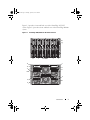
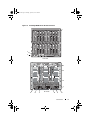
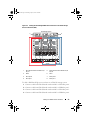
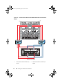
Figure 1-1 provides a front and back view of the PowerEdge 1855/1955
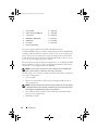
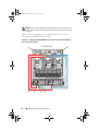
system. Figure 1-2 provides a front and back view of the PowerEdge M1000e
system.
Figure 1-1. PowerEdge 1855/1955 Server Enclosure Overview
back view
front view
1
13
3
10
8
6
7
34
1
2
9
2
11
12
4
5
book.book Page 7 Monday, April 19, 2010 5:06 PM

8 Introduction
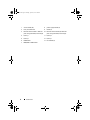
1 server module (10) 8 power supply module (4)
2 front-panel indicators 9 blanks (2)
3 Ethernet switch module or Ethernet
pass-through module (not shown) (2)
10 Ethernet switch module (2) or Ethernet
pass-through module (not shown) (2)
4 I/O bay 1 11 I/O bay 4
5 I/O bay 3 12 I/O bay 2
6 KVM module 13 fan modules (2)
7 DRAC/MC or CMC module
book.book Page 8 Monday, April 19, 2010 5:06 PM

Introduction 9
Figure 1-2. PowerEdge M1000e Server Enclosure Overview
front view
1
2
3
C2
B2
A2
A1
B1
C1
17
18
1919
20
21
22
23
0
17
18
1919
20
21
22
23
0
back view
13
4
5
12
11
10
8
6
7
9
book.book Page 9 Monday, April 19, 2010 5:06 PM

10 Introduction
The power supply modules, fan modules, Dell Remote Access
Controller/Modular Chassis or Chassis Management Enclosure (DRAC/MC
or CMC), and I/O modules are shared resources of the server modules in the
chassis. The system may ship with an optional external Universal Serial Bus
(USB) diskette drive and an optional external USB CD drive, which you can
use to set up and configure the server modules.
For information on supported cluster configurations, see "Cabling Your Blade
Cluster Hardware" on page 25. For a list of supported hardware and software
components, see the Support Matrix at dell.com.
NOTE: To ensure proper operation and cooling, all bays must be populated with
either a server module or a blank prior to turning on the system.
The PowerEdge server enclosure includes the following hardware components
for a cluster configuration:
•Server modules
• Ethernet switch modules or Ethernet pass-through modules (based on
your configuration)
NOTE: Throughout this document, Ethernet switch modules refer to either Gigabit
or 10 Gigabit Ethernet switch modules and Ethernet pass-through modules refer to
either Gigabit or 10 Gigabit Ethernet pass-through modules.
• Fibre Channel switch modules or Fibre Channel pass-through modules
(based on your configuration)
•DRAC/MC or CMC
1server module 8I/O bay A2
2 power switch and KVM ports 9 I/O bay B2
3 control panel 10 I/O bay C2
4 DRAC/MC or CMC module 11 I/O bay C1
5 KVM module 12 I/O bay B1
6 fan module 13 I/O bay A1
7 power supply module
book.book Page 10 Monday, April 19, 2010 5:06 PM

Introduction 11
Dell Remote Access Controller/Modular Chassis or Chassis Management Enclosure
The Dell Remote Access Controller/Modular Chassis or Chassis Management
Enclosure (DRAC/MC or CMC) is a management module located in the
back of the blade server system chassis that provides all of the chassis
management functionality. The DRAC/MC or CMC provides serial and
out-of-band Ethernet management ports to allow for management of the
chassis and some basic blade functions.
The following is a list of features available on the DRAC/MC or CMC. Your
system may have updates that enable additional features. Refer to the latest
Dell Remote Access Controller/Modular Chassis User’s Guide or Chassis
Management Controller User’s Guide at support.dell.com.
• Remote management and monitoring of a system through the DRAC/MC
web-based graphical user interface (GUI), serial connection, or telnet
connection.
• Access to the chassis System Event Log (SEL) and DRAC/MC or CMC
logs.
• Integrated launch of the DRAC/MC or CMC interface from the Dell
OpenManage™ IT Assistant.
• Ability to alert you to potential problems on the DRAC/MC or CMC by
sending either an e-mail message or an SNMP trap through the
DRAC/MC or CMC NIC to a management station.
• Ability to configure the DRAC/MC or CMC and update DRAC/MC or
CMC firmware using a telnet session, a web-based user interface, or
through a terminal session (for example, a hyperterminal or similar
program).
• Ability to manage controller configurations, I/O modules configurations
and settings, and perform power management functions such as
shutdown, power up, and reset, from a telnet session.
• Web-based interface password-level security management.
• Role-based authority that provides assignable permissions for different
systems management tasks.
book.book Page 11 Monday, April 19, 2010 5:06 PM

12 Introduction
Server Modules
Depending on the PowerEdge blade server module you choose for your
cluster, the number of available expansion ports and dual inline memory
modules (DIMMs) varies. Table 1-1 provides details about the supported
PowerEdge server modules and PowerEdge server enclosures.
In a Dell PowerEdge high availability cluster configuration, each server
module requires at least one expansion card. Expansion cards for either Fibre
Channel or Ethernet (for iSCSI) are available, and allow the server module to
communicate with the shared storage system for the cluster. The expansion
cards, also known as daughter cards or mezzanine cards, are installed on the
server module and contain two I/O ports. These I/O ports are internally
connected to two separate I/O modules in the server enclosure. By attaching
to two separate I/O modules, an expansion card can provide redundant paths
and load balance the I/O from the server module to the shared storage
system(s) for the PowerEdge cluster solution. Table 1-1 outlines the number
of expansion cards that are available on each supported server module.
Each server module is also configured with two additional Ethernet ports for
cluster interconnects. These are internally connected to two separate
Ethernet pass-through or Ethernet switch modules in the server enclosure.
With certain server modules, it is also possible to configure additional
Ethernet ports, which can enable the use of NIC teaming on the cluster
public network.
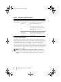
Table 1-1. PowerEdge Blade Server Features
Server Enclosure 1855/1955 M1000e
Supported blade server
modules
PowerEdge 1855, 1955 See the Support Matrix at
dell.com/ha for
information on supported
blade server types.
Maximum number of server
modules per server enclosure
10 16
Number of mezzanine card
slots per server module
12
book.book Page 12 Monday, April 19, 2010 5:06 PM

Introduction 13
Gigabit or 10 Gigabit Ethernet
The following are the Ethernet network connections available, depending on
your configuration:
• Public connection from the server modules to the public network
• Private node-to-node connection between the server modules for the
private network
• iSCSI connection between the server modules and storage system(s). For
more information, see "Supported Cluster Configurations" on page 16.
The server modules include two integrated Ethernet network interface cards
(NICs). You must configure at least two networks for each PowerEdge cluster
solution. One cluster network is configured for heartbeat communications
(private network) and is only accessible to the server modules in the cluster.
The other cluster network is configured for the client network (public
network) and is accessible to client systems. It is recommended that you
configure the same network interface on each node for the same role in the
cluster. For example, you can use the two integrated NICs to provide the
private and public cluster networks. Such a configuration allows an expansion
card in the server module to provide the I/O interface for the shared storage
system(s) in the cluster. Use an Ethernet expansion card for iSCSI shared
storage systems and use a Fibre Channel expansion card for Fibre Channel
shared storage systems. For more information about iSCSI and Fibre Channel
clusters, see "Supported Cluster Configurations" on page 16.
Ethernet Switch Module
The Ethernet switch module provides a switched connection to the
integrated NICs on each server module. Using the internal connections in the
system chassis, the Ethernet switch module can be used to provide the
following configurations:
• A switched connection to the client network (public network).
• Network connection to one or more server modules in the Cluster
configuration (private network).
• iSCSI connection between the server modules and storage system(s). For
more information, see "Supported Cluster Configurations" on page 16.
book.book Page 13 Monday, April 19, 2010 5:06 PM

14 Introduction
Ethernet Pass-Through Module
The Ethernet pass-through module provides a non-switched connection
between the server modules and an external Ethernet device.
Table 1-2 summarizes the supported Ethernet module configurations.
The following are the supported cable types for Gigabit Ethernet:
• Optical cables with LC connectors
• CAT5e cables with RJ45 connectors
• CAT6 cables with RJ45 connectors
The following are the supported cable types for 10 Gigabit Ethernet:
• Optical cables with LC connectors
• CAT6 cable with RJ45 connectors
• SFP+ Direct Attached cables
NOTE: For information about supported cable types to connect the blade chassis to
an external switch or storage system, see the switch documentation.
Fibre Channel Module
You can configure the PowerEdge blade cluster with two hot-pluggable Fibre
Channel switch modules installed on a PowerEdge 1855/1955 system or up to
four hot-pluggable Fibre Channel switch/pass-through modules installed on
the PowerEdge M1000e system to provide Fibre Channel connection between
the server modules and storage system(s).
Table 1-2. Supported Ethernet Module Configurations
Ethernet Switch Module for iSCSI Ethernet Pass-Through Module for iSCSI
Switch-attached configuration to
four supported Dell/EMC or
PowerVault iSCSI storage systems or
one PS Series group
Direct-attached configuration to a
Dell/EMC or PowerVault iSCSI storage
system
Switch-attached configuration to an
external iSCSI network with up to
four supported Dell/EMC or
PowerVault iSCSI storage systems or
one PS Series group
Switch-attached configuration to an
external iSCSI network with up to four
supported Dell/EMC or PowerVault
iSCSI storage systems or one PS Series
group
book.book Page 14 Monday, April 19, 2010 5:06 PM

Introduction 15
For more information about the Fibre Channel modules, see your Dell
PowerEdge system documentation.
Fibre Channel Switch Module
The Fibre Channel switch module provides a switched connection between
the Fibre Channel daughter card in the server modules and a supported Fibre
Channel device. The switch module functions as a director, mapping requests
and responses between the interconnected devices.
Additionally, the Fibre Channel switch module includes an internal serial port
that communicates with the DRAC/MC or CMC module.
The Fibre Channel switch module supports the following configurations:
• Switch-attached configuration with up to two supported Dell/EMC
storage systems
• Switch-attached connection to an external storage area network (SAN)
with up to four supported Dell/EMC storage systems
Fibre Channel Pass-Through Module
The Fibre Channel pass-through module provides a direct connection between
the Fibre Channel daughter card in the server modules and a supported Fibre
Channel device. The pass-through module functions as a dedicated link
between the server modules and specific ports on the pass-through module.
The pass-through module supports the following configurations:
• Direct-attached configuration to a supported Dell/EMC storage system
• Switch-attached connection to an external SAN with up to four supported
Dell/EMC storage systems
Table 1-3 summarizes the supported Fibre Channel module configurations.
book.book Page 15 Monday, April 19, 2010 5:06 PM

16 Introduction
Supported Cluster Configurations
The PowerEdge blade servers support both Fibre Channel and iSCSI cluster
configurations using either Fibre Channel mezzanine cards or Ethernet
mezzanine cards to connect to the corresponding shared storage system in
either direct-attached or
switch
-attached environments.
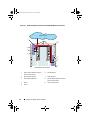
Direct-Attached Cluster
In a direct-attached cluster, the cluster nodes are directly attached to a single
storage system. The HBAs (mezzanine cards/daughter cards) in the nodes are
internally connected to the pass-through modules. The pass-through modules
are connected by cables directly to the RAID controllers (or storage
processors) on the storage system.
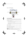
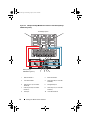
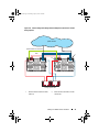
Figure 1-3 shows the logical components of a direct-attached cluster
configuration.
Table 1-3. Supported Fibre Channel Module Configurations
Fibre Channel Switch Module Fibre Channel Pass-through Module
Network-attached configuration to one or
two supported Dell/EMC Fibre Channel
storage systems using embedded Fibre
Channel switch modules
Direct-attached configuration to a
Dell/EMC Fibre Channel storage system
Switch
-attached configuration to an
external SAN with up to four supported
Dell/EMC Fibre Channel storage systems
Switch
-attached connection to an
external SAN with up to four supported
Dell/EMC Fibre Channel storage
systems
book.book Page 16 Monday, April 19, 2010 5:06 PM

Introduction 17
Figure 1-3. Direct-Attached Cluster
Switch-Attached Cluster
Switch
-attached clusters provide configuration flexibility, expandability, and
performance. In a
switch
-attached cluster, all of the nodes (server modules)
are attached to redundant switch fabrics. A
switch
-attached cluster supports
the following configurations:
• Up to two storage systems using embedded fibre channel switch modules
without external fibre channel switches
• Up to four storage systems using Ethernet switch modules, or embedded
fibre channel (switch or pass-through) modules connected to external fibre
channel switches
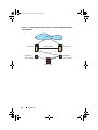
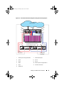
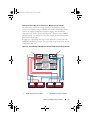
Figure 1-4 shows the switch-attached cluster connected to an external SAN
using switch modules.
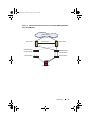
Figure 1-5 shows the switch-attached cluster connected to an external SAN
using embedded pass-through modules.
Figure 1-6 shows the switch-attached cluster connected to an external SAN
using embedded switch modules.
NOTE: Figure 1-4 through Figure 1-6 are for illustration only. Some cluster connections
shown below are routed internally through the PowerEdge server enclosure.
public network
cluster node
cluster node
pass-through module
private network
chassis connections
storage system
book.book Page 17 Monday, April 19, 2010 5:06 PM

18 Introduction
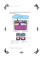
Figure 1-4. Switch-Attached Cluster Connected to an External SAN Using Embedded
Switch Modules
cluster node
cluster node
private network
storage system
embedded
switch module
embedded
switch module
public network
book.book Page 18 Monday, April 19, 2010 5:06 PM

Introduction 19
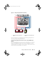
Figure 1-5. Switch-Attached Cluster Connected to an External SAN Using Embedded
Pass-Through Modules
cluster node
cluster node
private network
storage system
embedded pass-
through module
public network
external switch
embedded pass-
through module
external switch
book.book Page 19 Monday, April 19, 2010 5:06 PM

20 Introduction
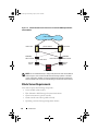
Figure 1-6. Switch-Attached Cluster Connected to an External SAN Using Embedded
Switch Modules
NOTE: It is recommended that you configure the paired inter-switch links (ISLs) as
shown in Figure 1-6 for clusters with Fibre Channel storage systems. In an iSCSI
cluster configuration, multiple connections between internal switch modules and
external switches may not be practical depending on the Ethernet switch features.
Blade Server Requirements
Your cluster requires the following components:
• Server modules (cluster nodes)
• Fibre Channel or iSCSI storage subsystem interconnects
• Cluster interconnects (private network)
• Client network connections (public network)
• Operating system and storage management software
cluster node
cluster node
private network
storage system
embedded
switch module
public network
external
switch
embedded
switch module
external
switch
inter-switch link
inter-switch link
book.book Page 20 Monday, April 19, 2010 5:06 PM
Page is loading ...
Page is loading ...
Page is loading ...
Page is loading ...
Page is loading ...
Page is loading ...
Page is loading ...
Page is loading ...
Page is loading ...
Page is loading ...
Page is loading ...
Page is loading ...
Page is loading ...
Page is loading ...
Page is loading ...
Page is loading ...
Page is loading ...
Page is loading ...
Page is loading ...
Page is loading ...
Page is loading ...
Page is loading ...
Page is loading ...
Page is loading ...
Page is loading ...
Page is loading ...
Page is loading ...
Page is loading ...
-
 1
1
-
 2
2
-
 3
3
-
 4
4
-
 5
5
-
 6
6
-
 7
7
-
 8
8
-
 9
9
-
 10
10
-
 11
11
-
 12
12
-
 13
13
-
 14
14
-
 15
15
-
 16
16
-
 17
17
-
 18
18
-
 19
19
-
 20
20
-
 21
21
-
 22
22
-
 23
23
-
 24
24
-
 25
25
-
 26
26
-
 27
27
-
 28
28
-
 29
29
-
 30
30
-
 31
31
-
 32
32
-
 33
33
-
 34
34
-
 35
35
-
 36
36
-
 37
37
-
 38
38
-
 39
39
-
 40
40
-
 41
41
-
 42
42
-
 43
43
-
 44
44
-
 45
45
-
 46
46
-
 47
47
-
 48
48


Dell EqualLogic PS Series iSCSI Storage Arrays Owner's manual
- Type
- Owner's manual
Ask a question and I''ll find the answer in the document
Finding information in a document is now easier with AI
Related papers
-
Dell 350 User manual
-
-
-
Dell PowerEdge M805 User guide
-
Dell EqualLogic PS6100E User manual
-
-
-
-
-
