Sharp ViewcamZ VL-Z700S-T User manual

Category
Camcorders
Type
User manual
VL-Z700S-T
VL-Z800S-S/E-S/E-T/Z900H-S
VL-Z950S-S/E-A/E-S/E-T/E-W
1
In the interests of user-safety (Required by safety regula-
tions in some countries) the set should be restored to its
original condition and only parts identical to those specified
be used.
S34Q4VL-Z700S
LIQUID CRYSTAL DISPLAY CAMCORDER PAL
SERVICE MANUAL
CONTENTS
SHARP CORPORATION
VL-Z700S-T
VL-Z800S-S/E-S/
E-T
VL-Z900H-S
VL-Z950S-S/E-A/
E-S/E-T/E-W
MODELS
Page
1. SPECIFICATIONS .............................................................................................................................. 2
2. PART NAMES .................................................................................................................................... 3
3. DISASSEMBLY OF THE SET ............................................................................................................ 4
4. MECHANISM ADJUSTMENT JIGS AND PARTS .............................................................................. 8
5. INSPECTION AND MAINTENANCE
ITEMS AND INTERVALS ................................................................................................................... 9
6. ADJUSTING AND CHECKING OF MECHANISM ........................................................................... 10
7. ADJUSTMENT OF RUNNING SYSTEM .......................................................................................... 13
8. ASSEMBLING OF MECHANISM SECTION AND PART REPLACEMENT
(DISASSEMBLING AND ASSEMBLING) ........................................................................................... 15
9. METHOD OF ADJUSTING THE ELECTRIC CIRCUIT .................................................................... 25
10.USEFUL TIPS ................................................................................................................................... 44
11.SIGNAL FLOW DIAGRAMS ............................................................................................................. 45
12.BLOCK DIAGRAMS ......................................................................................................................... 48
13.SCHEMATIC DIAGRAMS ................................................................................................................ 54
14.SEMICONDUCTOR LEAD IDENTIFICATION ............................................................................... 140
15.PRINTED WIRING BOARD ASSEMBLIES .................................................................................... 142
16.REPLACEMENT PARTS LIST ....................................................................................................... 159
17.PACKING OF THE SET ................................................................................................................. 185
VL-Z700S-T/Z800S-S/E-S/E-T
VL-Z900H-S/Z950S-S/E-A/E-S/E-T/E-W
2
VL-Z700S-T
VL-Z800S-S/E-S/E-T/Z900H-S
VL-Z950S-S/E-A/E-S/E-T/E-W
1. SPECIFICATIONS
Signal System: PAL standard
Recording System: 2 rotary heads, helical scanning system
Cassette: Digital VCR Mini DV video cassette
Recording/Playback Time: 90 minutes (DVM60, LP mode)
Tape Speed: SP mode: 18.831mm/second
LP mode: 12.568 mm/second
Pickup Device:
1
/
4
" (6.4 mm, effective size: 3.0 mm) CCD image sensor
(with approx. 1,330,000 pixels including optical black,
effective pixels: 690,000 pixels in Tape Camera mode,
1,250,000 pixels in Card Camera mode)
Lens: 10 × optical zoom lens (F1.8, f=3.8-38.0 mm)
Lens Filter Diameter: 30 mm
Monitor: 2.5" (6.4 cm) CGSilicon
Viewfinder: 0.16" LCD panel (with 113.578 pixels), slide type
Built-in Microphone: Electret stereo microphone
Color Temperature Compensation: Auto white balance with white balance lock, outdoor or in door
Minimum Illumination: 3 lux* (with gain-up, F1.8)
Still Image Compression System: JPEG base line conformance
Still Image Recording Format: JPEG (Exif2.2)
USB Terminal: Mini-B type connector (USB 1.1 version)
DV terminal: 4 pin connector (i.LINK)
Still Image Recording Medium: SD Memory Card, MultiMediaCard
Power Requirement: DC 7.4 V
Power Consumption: 3.8 W (during camera recording in Tape Camera mode using the viewfinder in Full
Auto mode with the DIS function on)
4.3 W (during camera recording in Tape Camera mode using the LCD monitor
in Full Auto mode with the DIS function and backlight in normal mode)
Operating Temperature: 0°C to +40°C
Operating Humidity: 30% to 80%
Storage Temperature: –20°C to +60°C
Dimensions (approx.): VL-Z800/Z700: 82.9 mm (W) × 86.2mm (H) × 100.8 mm (D)
VL-Z900/Z950: 82.9 mm (W) × 86.2mm (H) × 103.3 mm (D)
Weight (approx.): VL-Z800/Z700: 495 g
VL-Z900/Z950: 500 g
(without battery pack, lithium battery, video cassette, lens cap and card)
AC Adapter (UADP-A053TAZZ)
Power Requirement: AC 110-240 V, 50/60 Hz
DC Output: 10 V
Dimensions (approx.): 49.0 mm (W) × 27.5 mm (H) × 79.0 mm (D)
Specifications are subject to change without notice.
*Minimum illumination: Since there is no widely accepted testing procedure for determining minimum illumination
capability, lux ratings are comparable only between models from the same manufacturer.
VL-Z700S-T
VL-Z800S-S/E-S/E-T/Z900H-S
VL-Z950S-S/E-A/E-S/E-T/E-W
3
2. PART NAMES
Viewfinder
Power Zoom Wide angle/
Telephoto control/
VOLume control
Media Selection
switch ( Tape
mode/
Card
mode selection
switch)
Record Start/Stop button
PHOTO button
Power switch ( Camera
Recording mode/ Playback
mode select switch)
Z700/Z800/Z950: STANDBY
button
STANDBY indicator
POWER/CHARGE
(RED) indicator
Cassette holder
Cassette compartment
door release
Cassette com
p
artment door
Right view
Hand strap
Speaker
Window cleaning cover
Z900: STANDBY/
_
PC
button
Lithium battery cover
Tripod socket*
Card slot cover
Left view
Dioptre adjustment dial
Battery release
* When attaching a tripod
with a guide pin, do not
attach the pin to the bottom
of the camcorder.
LCD monitor
Earphones jack
DV terminal
USB terminal
DC IN jack
AV terminal
Terminal cover
Zoom lens
DISPLAY/MODE SET button/
LCD LAMP button
Operation button
Built-in LED video
light
Zoom microphone
shoe*
Stereo microphone
MENU button
* The zoom microphone shoe is designed only
for the optional zoom microphone VR-8MC.
Accessories, such as a video light, cannot be
used.
Front view
VL-Z800/Z700
Zoom lens
DISPLAY/MODE SET button/
LCD LAMP button
Operation button
Flash
Z950: Zoom microphone/
LED video light shoe
Z900: Zoom microphone
shoe
Stereo microphone
MENU button
Flash sensor
Front view
VL-Z900/Z950
4
VL-Z700S-T
VL-Z800S-S/E-S/E-T/Z900H-S
VL-Z950S-S/E-A/E-S/E-T/E-W
3. DISASSEMBLY OF THE SET
3-1. Procedure for disassembling the cabinet
Note: Before removing the cabinet, turn OFF the power and make sure that the battery is not connected.
1.
· Remove the screw ((s) XiPSF14P06000).
· Open the LCD panel 90 degrees and remove the two screws ((x) LX-
HZ0050TAFN).
· Remove the two screws ((c) XiPSN17P04000) and remove the
camera front cover by pulling it frontward.
2.
· Disconnect the connector of the camera front cover.
· Disconnect the two LCD tilt FPCs of the LCD panel.
· Remove the two screws ((r) XiPSN20P08000) and remove the LCD panel.
· Remove the screw ((p) LX-HZ0063TAFN) and screw ((q) XiPSN17P06000)
that hold the camera L cabinet, open the terminal cover and remove the three
screws ((b) XiPSN17P03000).
3.
· Disconnect the hot shoe FPC of the hot shoe and remove the camera L cabinet.
· Remove the screw ((c) XiPSN17P04000) and remove the camera bottom
cover.
· Disconnect the INNER LED FPC or strobe FPC, remove the two screws ((a)
XiPSN17P02000) and remove the INNER LED Unit or strobe unit.
Ã¥ Precautions in servicing the strobe unit
Once put in the card mode, the main condenser of the strobe unit stays still
electrically charged. If touching the strobe unit or its nearby parts, you may
get an electric shock.
To avoid this, connect a 7 kΩ resistor (300-V withstand voltage) across the
main condenser for about 10 seconds. The condenser will be discharged.
s
c
x
LCD panel
Camera front cover
x
c
r
r
p
b
b
q
Camera L cabinet
Connector
LCD tilt FPC
Camera front cover
Terminal cover
Camera front cover
LCD panel
b
VL-Z700/Z800 VL-Z900/Z950
a
a
Camera
bottom cover
Camera L cabinet
Strobe FPC
INNER LED
FPC
Strobe unit
INNER LED unit
Hot shoe FPC
c
a
a
VL-Z700S-T
VL-Z800S-S/E-S/E-T/Z900H-S
VL-Z950S-S/E-A/E-S/E-T/E-W
5
6.
7.
4.
b
a
p
b
x
Camera unit
Camera top cover
VF
FPC(3)
FPC(2)
FPC(1)
· Remove the screw ((x) LX-HZ0050TAFN), screw ((p) LX-
HZ0063TAFN) and screw ((a) XiPSN17P02000), disconnect
the FPC (1) and remove the camera top cover.
· Remove the screw ((b) XiPSN17P03000) from the camera
unit, disconnect the FPC (2) and remove the camera unit.
· Remove the screw ((b) XiPSN17P03000), disconnect the
FPC (3) and remove the VF.
5.
· Disconnect the two connectors of the sub PWB unit and main
PWB unit.
· Remove the two screws ((b) XiPSN17P03000) from the heat
release angle, remove the screw ((b) XiPSN17P03000) from
the PWB unit and remove each unit.
· Disconnect the two FFCs of the main PWB unit.
· Remove the two screws ((x) LX-HZ0050TAFN), remove the
screw ((x) LX-HZ0050TAFN) form the PWB mounting angle
and remove the terminal cabinet.
· Remove the screw ((b) XiPSN17P03000) and remove the
Mechanism reversion detection PWB unit.
· Remove the three screws ((u) LX-BZ0221TAFC) and remove
the PWB mounting angle.
· Turn the LCD tilt unit assembly 90 degrees.
· Remove the three screws ((b) XiPSN17P03000).
· Remove the screw ((a) XiPSN17P02000).
x
b
b
b
x
Main PWB unit
Terminal cabinet
Heat release angle
Sub PWB unit
Tilt FPC
Connector
PWB mounting angle
x
LCD tilt unit assembly
b
b
b
a
b
u
u
u
Mechanism reversion detection PWB unit
PWB mounting angle
6
VL-Z700S-T
VL-Z800S-S/E-S/E-T/Z900H-S
VL-Z950S-S/E-A/E-S/E-T/E-W
3-2. Procedure for disassembling the cabinet
VCR bottom cover
a d
b e
or
b e
or
b e
or
or
h
h
h
Tilt cover
VCR front cover
Connector
Tilt FPC
Camera tilt
e
b
or
e
b
or
f1
VCR operating cover
Operating PWB FFC
The internal lug
may be damaged
If the VCR front cover is removed
only by turning it in the direction
indicated
1. Remove the two couplings and turn the VCR front cover about 20 degrees in
the direction indicated by (1).
2. Turn the VCR front while sliding it in the direction indicated by (2) to disengage
the internal lug.
* If the VCR front cover is removed by turning it forcedly in the direction indicated
by (1), the internal lug may be damaged.
How to remove the VCR front cover
1
2
1.
· Remove the three screws Z800E-T: ((e) XiPSF17P03000) or Z700/
Z800S-S/E-S/Z900/Z950: ((b) XiPSN17P03000) remove the screw
Z800E-T: ((d) XiPSF17P02000) or Z700/Z800S-S/E-S/Z900/Z950:
((a) XiPSN17P02000) and remove the VCR bottom cover.
2.
· Remove the two screws Z700/Z800S-S/E-S/Z900/Z950: ((b)
XiPSN17P03000) or Z800E-T: ((e) XiPSF17P03000) and remove the
tilt cover.
· Remove the VCR front cover with the cassette cover opened.
· Disconnect the connector and two tilt FPCs, remove the three screws
((h) LX-BZ0220TAFC) and remove the camera tilt.
3.
· Remove the screw ((f1) XiPSF17P04000) with the cassette lid
opened, disconnect the operation PWB FFC and remove the VCR
operating cover.
VL-Z700S-T
VL-Z800S-S/E-S/E-T/Z900H-S
VL-Z950S-S/E-A/E-S/E-T/E-W
7
4.
· Disconnect the six FPCs of the head amp circuit board
unit.
· Remove the two screws ((a) XiPSN17P02000) and
remove the head amp PWB unit.
· Remove the three screws ((w) LX-BZA022WJFN) and
remove the screw ((k) LX-BZA023WJFD).
· Remove the mechanism with the cassette lid opened.
5.
· Remove the screw ((x) LX-HZ0050TAFN).
· Remove the two screws Z800E-T: ((d) XiPSF17P02000) or Z700/
Z800S-S/E-S/Z900/Z950: ((a) XiPSN17P02000) and remove the
cassette lid.
6.
· Remove the two screws ((d) XiPSF17P02000).
· Disconnect the connector of the speaker while removing the Lid upper
cover with the cassette control lid opened.
· Remove the screw ((a) XiPSN17P02000) and remove the lock guide
cover.
· Remove the speaker.
x
Cassette lid
a
a d
or
d
or
d
d
Connector
Speaker
Lock guide cover
Lid upper cover
a
k
a
a
w
w
w
Mechanism
Head amp PWB unit
FPC
8
VL-Z700S-T
VL-Z800S-S/E-S/E-T/Z900H-S
VL-Z950S-S/E-A/E-S/E-T/E-W
4. MECHANISM ADJUSTING JIGS AND PARTS
4-1. Mechanism checking and adjusting jigs
1. Cassette torque
meter for PB
2. 9DASD-1015
3. DB
* 1mN·m/1.5mN·m
1. Torque gauge
2. JiGTG0045
3. CN
* For measurement of VS-
REW winding torque
1. Torque gauge head
2. 9EQTGH-DH5000
3. BW
*
For torque gauge shown
left
1. Dial tension gauge
2. 9DAPTG-10-10W
3. CA
* PTG-10
1. Tension gauge 4N
2. JiGSG0400
3. BK
* For measurement of
pinch roller press force
1. Master plane
2. 9EQMP-VLPD1
3. CL
* For checking of
height of reel table
1. Height adjustment jig
2. 9DAHG-PD1
3. BZ
* For height adjustment
1. Alignment tape – (II)
2. VR3-JPZQS
3. CG
* For adjustment of SW
point(Color bar signal)
* 90ADVC-TAPEPAL
available
1. Torque driver
150mN·m
2. JiGTD1500RTDH
3. CB
4-2. Parts for periodic inspection and maintenance
1. Oil
Cosmo Hydro HV22
2. 9EQ-OiL-HV22
3. AE
* Cosmo Oil Co., Ltd.
<How to make mechanism checking and adjusting jigs>
(1) Reel hub for back tension measurement (Fig.1)
1) Have the reel hub of a commercially available cassette
tape ready.(Disassemble the cassette tape and remove
the tape from the reel hub.)
2) Attach one end of a thread (having a length of about
20cm) to the reel hub using Scotch tape etc.
3)
Attach a weight of about 0.21N to the top face of the reel hub.
(2) Thread for pinch roller press force measurement
1) Have a commercially available thread having a length of
about 20cm ready.
1. Driver for height
adjustment
2. 9EQDRiVER-DH5
3. BC
<Miscellaneous>
(1) Vernier calipers
(2) Precision screwdriver
(Phillips head and slot-
ted)
(3) Long-nose pliers
(with thin tips)
(4) Tweezers
1. Bit for hexagon nut
with opposite side
distance of 3 mm
2. 95CM22001
3. BL
* For installation of Tu
guide nut
1. Cleaning paper
2. JiGDUSPER
3. AP
* DUSPER ∑ (SIGMA)
(Ozu Co., LTD.)
1. Ultrathin cotton swab
* Commercial item
1. Cleaning liquid
Industrial ethyl alcohol
* Commercial item
1. Loctite adhesive (1401B)
* Three Bond
1. Grease
Molykote YM-103
2. 99FGREASEYM103
* Dow Corning
1. Alignment tape – (I)
2. VR3-GAZXS
3. CF
* Adjustment of running
system
(Linear signal)
ø2
50 or more
No.0 Phillips bit
No.00 Phillips bit
1. Dry grease CFD-409Z
* Sankei Chemical Co., LTD.
<Note: Order of descriptions>
Sketch
1. Name
2. Part code
3. Code
* Model number and usage
* For adjustment of guide
roller
* Bit shape
(see figure below)
Tolerance ± 0.1
Tip thickness 0.5
1.4
3
2
<Note: Order of descriptions>
1. Name
2. Part code
3. Code
* Model number and usage
2) Tie both ends together to loop the thread.
Fig. 2
Fig. 1
Weight
Reel hub
Thread
Thread
VL-Z700S-T
VL-Z800S-S/E-S/E-T/Z900H-S
VL-Z950S-S/E-A/E-S/E-T/E-W
9
5-2. Cautions in handling the mechanism
(1) Cut washers removed at the time of part replacement etc. should be
replaced with new ones without fail.
(2) Because no volume adjustment is available in this mechanism, cleaning or
part replacement should be performed if the setting is not satisfied.
(3) About oil
a) Be sure to use the specified oil. (If any oil other than the specified oil is
used, various troubles will occur.)
b) When lubricating the bearing, be sure to oil free from foreign particles
such as dust. (If oil in which foreign particles such as dust are mixed is
used, it will cause wear and seizure to the bearing.)
c) The term "One drop of oil" here means the amount of oil on the point of
a needle etc. shown in Fig.1.
(4) Repairing of circuits, final adjustment of running system, etc. should be
performed with the cassette controller assembly installed in the mechanism.
(5) When operating the mechanism singly, apply voltage to the loading motor
to drive it. The voltage between the terminals should be 3 to 4V DC. (Do
not apply external voltage to the loading motor with the mechanism
connected with the main circuit board. Doing so could cause a failure.)
(Turning the gears forcedly by hand may cause them to get damaged.)
When placing the mechanism singly, use an appropriate spacer so that the
capstan motor is not rubbed.
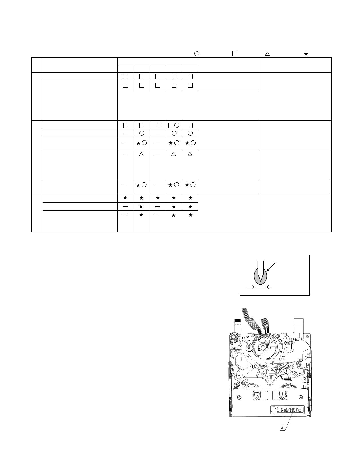
(6) When installing the cassette controller, push the portion indicated by "A" in
Fig.2. Do not push other portions.
(7) Take care not to deform the components of the mechanism.
Fig. 2
Ø1.5 or less
Oil
Fig. 1
5. INSPECTION AND MAINTENANCE ITEMS AND INTERVALS
In order to maintain the quality of the mechanism section, perform the following maintenance and inspection. After repairing the
mechanism section, perform the following maintenance regardless of the number of hours of use by the user.
5-1. Maintenance and inspection list
Tape running section (See7-3.)
Swing arm
S reel table, Tu reel table
Running system
• • • Replace. • • • Clean. • • • Lubricate. • • • Check.
Note:
If no envelope output is obtained
in spite of the video head being
cleaned, replace the drum
component.
(If the envelope output is normal,
refer to "10. USEFUL TIPS".)
Performance check
[Oil] Cosmo Hydro HV22
[Grease] Molykote YM-103
Sankei Chemical CFD-409Z
Driving system
Number of hours of use (h)
500 1,000 1,500 2,000 3,000
Symptoms observed at the
time of maintenance
Notes and remarks
Inspection and
maintenance location
[Loctite adhesive] Three Bond 1401B
[Cleaning liquid] Industrial ethyl alcohol
• Tape not running
• Tape sagged
• Block noise
• Abnormal noise
• Replace if any abnormal
condition is found.
• Apply oil.
[Oil]
Cosmo Hydro HV22
Note:
Apply oil to the shaft and
lightly wipe it off with a cloth.
• Abnormal noise
• Ejecting cannot be made.
• Mode cannot be set.
• Replace if any abnormal
condition (noise etc.) is found.
• Tape not running
• Tape sagged
• Damage to tape
• Abnomaly in reproduced
picture
• If a part is out of spec, replace
it.
PB, VS/R and loading back tension
S reel table unloaded torque
PB and VS/R winding torque
Abnormal noise
Loading motor
Mode SW
Center gear boss
Relay pulley shaft
Capstan motor (Timing belt)
Pinch roller
Drum section, Video head
(See 7-3.)
<Rollers>
• Replace if abnormal rotation or swing (large) is found.
<Others>
• Cleans the portions that come in contact with the tape (the lower
drum helical portion in particular). Use the specified cleaning liquid.
• Block noise
• Clogging of head
• Damage to tape
10
VL-Z700S-T
VL-Z800S-S/E-S/E-T/Z900H-S
VL-Z950S-S/E-A/E-S/E-T/E-W
6-1. Checking of PB (REC) winding torque
AC adapter used, Cassette controller assembly installed
(1) Set the torque cassette with the cassette controller installed in the mechanism. In the SP record mode (or in the PB mode
if signals have been SP-recorded on the tape), check that the winding torque is within spec.
<Spec for PB (REC) winding torque>(If there is a torque ripple, read the center value.)
0.7+0.2/-0.05N·m, Ripple: 0.1mN·m or less
6-3. Checking of height of reel table
3 to 4V DC, Cassette controller assembly not installed (Mechanism only)
(1) Remove the cassette controller. (Refer to 8-2.)
(2) Apply 3 to 4V DC to the loading motor while referring to 8-1 and select the
PB mode.
(3) Fit the holes of the master plane to the two guides (portions A and B) shown
in the Fig.2, taking great care not to allow master plane to strike the running
parts such as the drum and guide roller or the MIC contact.
(4) Using a pair of vernier calipers etc., measure the heights of the reel-supporting
faces of the S reel table and Tu reel table from the top face of the master plane
and check that the measured heights satisfy the set values. (Fig.3)
When measuring the height of the S reel table, push the tip of the tension
pole with your finger in the direction shown by Arrow A to release the tension
band. (Fig.1)
(5) If the measured height does not satisfy the set value, replace the reel table
and make checking again.
<Note> After replacement, select the L start mode (see 8-1) and check that the
reel table rotates smoothly.
6-2. Checking of VS-REW winding torque
AC adapter used, Cassette controller assembly not installed (Mechanism only)
(1) Remove the cassette controller, turn ON the down SW while referring to 8-3, operate
in the test mode (T01) and select the VS-REW mode.
(2) Set the torque gauge in the S reel table, push the tip of the tension pole with your finger
in the direction shown by Arrow A to release the tension band, and check that the
winding torque is within spec. (Fig.1) (Do not apply the own weight of the torque
gauge or rotate it during measurement.)
<Spec for VS-REW winding torque>
(If there is a torque ripple, read the center value.)
1.5 ± 0.15N·m, Ripple: 0.15mN·m or less
(3) After checking the winding torque, remove the torque gauge and turn OFF the down
SW. The mechanism will automatically go into the standby mode.
6. ADJUSTING AND CHECKING OF MECHANISM
The items described here are relevant to the general on-site servicing (field service). This section does not cover adjustment and
replacement for which sophisticated equipment, jigs and techniques are required.
In order to maintain the initial characteristics of the mechanism, it is necessary to perform maintenance and inspection and also it is
essential not to damage the tape etc. In the case of an adjustment that requires a jig, be sure to use the specified jig.
<Caution>
(1) When adjusting and checking the mechanism, be sure to see that the power supply and the status are as indicated in
Caution on the title.
(2) Do not apply external voltage to the loading motor with the mechanism connected with the main circuit board. (Doing
so could cause a failure.)
(3) When running the tape, be sure to do so with the cassette controller assembly installed.
A
B
MIC contact
Fig.2 Checking of reel table
Fig.1 How to release the tension
band when measuring the
VS-REW winding torque
Fig.3
Set value of height
of reel table
Set value of height
of reel table
2.4±0.1
2.4±0.1
(3)
Reel-supporting face
VL-Z700S-T
VL-Z800S-S/E-S/E-T/Z900H-S
VL-Z950S-S/E-A/E-S/E-T/E-W
11
6-4. Checking and adjusting of tension pole position during
REC (PB)
3 to 4V DC, Cassette controller assembly not installed (Mechanism only)
(1) Checking
Check that the tension pole is located in the prescribed position as shown in Fig.4
at the start of a 60-minute tape.
If the tension pole is not located in the prescribed position, take out the tape and
make adjustment according to the procedure shown below.
(2) Adjusting (See Fig.4.)
1. Select the PB mode without setting a tape.
2. Slightly loosen the screw 1 (to such an extent that the T band adjustment base
2 can be moved.)
3. If the tension pole is dislocated inward from the prescribed position, shift the
T band adjustment base 2 in the direction shown by Arrow (A). If it is dislocated
outward from the prescribed position, shift the T band adjustment base 2 in the
direction shown by Arrow (B). Then fix the T band adjustment base 2 with the
screw 1.
(For how much the T band adjustment base is to be shifted, refer to Fig.4.)
4. Check the tension pole position as described in "(1) Checking" above.
5. If out of position, make readjustment.
6-5. Checking and adjusting of REC (PB) back tension
torque
AC adapter used, Cassette controller assembly installed
(1) Checking
Set the torque cassette (SD-1015). In the SP record mode (or in the PB mode if
signals have been SP-recorded on the tape), check that the feed-side torque is
within the following spec.
<Spec>(If there is a torque ripple, read the center value.)
0.4 ± 0.05 mN·m
(2) Adjusting (See Fig.5.)
If the measured back tension torque is out of spec, make adjustment according
to the following procedure.
1. Slightly loosen the screw 3.
2. If the back tension is higher, shift the T-SPR adjustment ANG in the direction
shown by Arrow (D). If it is lower, shift the T-SPR adjustment ANG in the
direction shown by Arrow (C).
3. After adjusting the back tension torque, fix the T-SPR adjustment ANG with the
screw 3. Apply loctite adhesive to screw 3.
<Reference>
Screw tightening torque: 0.04 N·m
6-6. Checking of S reel table unloaded torque
3 to 4V DC, Cassette controller assembly not installed (Mechanism only)
(1) Remove the cassette controller assembly, apply 3 to 4V DC to the loading motor
and select the L start mode. (See 8-1.)
(2) Move the swing arm to the Tu reel table side. At this time, take care not to damage
the gears etc. (See Fig.6.)
(3) Set the reel hub for back tension measurement on the S reel table.
(4) Using the dial tension gauge, pull the thread of the reel hub in the direction shown
by Arrow A and check that the tension is within spec.
<Spec>
(If the tension fluctuates, read the center value.)
10mN or less
Screw 3
Tension pole position
(Based on drum base outside shape)
0±0.3
Drum base
T band adjustment
base 2
Screw 1
Fig.4 Adjusting of position (tape exists)
Fig.5 Checking (tape exists)
T pole
Fig.6 How to measure the S reel table unloaded torque
Move the swing arm to
the Tu reel table side.
A
Apply loctite
adhesive.
T-SPR adjustment ANG4
12
VL-Z700S-T
VL-Z800S-S/E-S/E-T/Z900H-S
VL-Z950S-S/E-A/E-S/E-T/E-W
6-7. Checking of loading back tension
3 to 4V DC, Cassette controller assembly not installed (Mechanism only)
(1) Apply 3 to 4V DC to the loading motor and select the L start mode. (See 8-1.)
(2) Move the swing arm to the S reel table side. At this time, take care not to damage
the gears etc. (See Fig.7.)
(3) Set the reel hub for back tension measurement on the Tu reel table.
(4) Using the dial tension gauge, pull the thread of the reel hub in the direction shown
by Arrow A and check that the tension is within spec.
<Spec>
(If the tension fluctuates, read the center value.)
27.5 ± 7.5mN
6-8. Checking of VS-REW back tension
3 to 4V DC, Cassette controller assembly not installed (Mechanism only)
(1) Apply 3 to 4V DC to the loading motor and select the VS-REW mode. (See 8-1.)
(2) Move the swing arm to the S reel table side. At this time, take care not to damage
the gears etc.
(3) Set the torque gauge in the Tu reel table.
(4) While turning the torque gauge counterclockwise (one turn in three seconds),
check that the torque is within spec.
<Spec>
(If the tension fluctuates, read the center value.)
0.8+0.2/-0.05mN·m
Move the swing arm
to the S reel table
side.
Fig.7 How to measure the loading back tension
A
Fig.9
OK
B
Fig.10
Fig.8
NG
Right guide
Pinch roller
Capstan shaft
6-9. Checking of pinch roller press force
3V DC, Cassette controller assembly not installed (Mechanism only)
(1) Hook the thread for pinch roller press force measurement over the pinch lever (position A in Fig.8).
(2) Put the mechanism into the PB mode to press the pinch roller against the capstan shaft.
(3) Hook the thread for pinch roller press force measurement over the tension gauge and pull the tension gauge in the direction shown
by Arrow B in Fig.10 so that the pinch roller is slightly separated from the capstan shaft.
(4) Return the pinch roller gradually and read the value indicated when the pinch roller comes in parallel contact with the capstan shaft
(see Fig.9). Check that the read value is within the following spec.
<Spec>
2.1+0.4N
<Note> After measuring the press force of the pinch roller, promptly exit from the PB mode to separate the pinch roller from the capstan
shaft. (If the pinch roller is left pressed against the capstan shaft for a long time, the pinch roller will be deformed.)
A
VL-Z700S-T
VL-Z800S-S/E-S/E-T/Z900H-S
VL-Z950S-S/E-A/E-S/E-T/E-W
13
7. ADJUSTMENT OF RUNNING SYSTEM
7-1. Outline of adjustment of running system
7-2. Adjustment of height of running system
· After replacement of the T pole, Tu guide and slide chassis, adjust the height of the T pole/Tu guide using the height adjustment jig.
· If wrinkles are found in the tape, turn the Tu guide to remove them.
(For further details, refer to "Coarse adjustment of running system".)
· After adjusting the T pole and Tu guide height, apply screw loctite at the tip of the shaft.
7-3. Preparations for adjustment of running system
Measuring instrument and Jig : Oscilloscope, Adjustment remote control, Height adjustment screwdriver, Alignment tapes (for
adjustment of running system and adjustment of SW point), Master plane, Height adjustment jig
Preparations for
adjustment of
Running system
Adjusting
procedure(8-3)
(Replacement parts)
· Tu guide and arm
· Slide chassis
· T arm Ass'y
(Replacement parts other
than above)
· Pole base
· Guide roller
· Drum assembly
· Cap motor, etc.
Presetting of height not
necessary
Coarse adjustment
of Running system
Adjusting
procedure(8-4)
Final adjustment
of Running system
Adjusting
procedure(8-5)
Installation of
cassette controller
Readjustment of height
Height
adjustment jig
Master plane
Lower edge
alignment
Align the top face of the lower flange of the Tu guide with
the bottom edge of the height adjustment jig.
After adjusting the height, turn the head clockwise 180
degrees.
Tu guide
Master plane
View A
Height
adjustment jig
Apply it in this direction.
View A
<Method and description>
(1) Clean the surfaces that come in contact with the tape. (Clean
well the drum surface and the lower drum helical surface in
particular.)
(2) Install the cassette controller.
(3) Connect the oscilloscope to each TP of the joint circuit board.
(4) Turn ON the power of the AC adapter.
(5) Select TEST mode T-05 with the adjustment remote control.
(6) Play back the alignment tape for running system adjustment
and check that the tape is moving in the SP mode.
(7) While observing the PB envelope on the oscilloscope, adjust
the running system so that the envelope becomes flat in
states of [+1/4 shift] and [-1/4 shift].
(Each time the PB key is pressed, the shift amount changes
as shown below.)
Reel
Tu guide
Tu guide roller
Drum
Sup guide roller
S guide
Pinch roller
Tension pole
Capstan shaft
+1/4 shift - Normal - -1/4 shift - Normal
Master plane
T pole
View B
View B
Height
adjustment jig
T pole Height setting Tu guide height setting
Lower edge
alignment
14
VL-Z700S-T
VL-Z800S-S/E-S/E-T/Z900H-S
VL-Z950S-S/E-A/E-S/E-T/E-W
7-4. Coarse adjustment of running system
(Cassette controller installed)
(1) Play back the alignment tape for running system
adjustment and make adjustment so that the inlet
and outlet sides of the envelope become flat.
(2)In states of [+1/4 shift] and [-1/4 shift], make
adjustment in the same manner as described in (1)
above.
A
Wrinkle
Pinch roller
Tu guide
Distortion
Distortion
(1) In the PB mode and V/SR mode, check the tape for
distortion between the Tu guide and the pinch roller.
- If wrinkles are found, make adjustment within a
range of ±180 degrees.
- After making adjustment, apply loctite adhesive to
the tip of the shaft.
(1) In the V/SR mode, check that the envelope waveform
is shaped uniformly.
(2) If the envelope waveform is not shaped uniformly,
fine-adjust the guide roller and Tu guide.
(1) Check the envelope waveform rise time in switching from the V/SR mode to the PB mode. - 5 seconds or less
(2) Check the envelope waveform rise time in switching from the STOP mode to the PB mode. - 5 seconds or less
2. Checking of V/SR envelope waveform
<Method and description>
1. Adjustment of height of Su and Tu guide rollers
<Method and description>
7-5. Final adjustment of running system
(Cassette controller installed)
Fig.1
1. Adjustment of height of Sup and Tu guide rollers
<Method and description>
(1) If the ratio of MIN to MAN of the envelope waveform is less
than 60%, adjust the height of the guide roller again. (See
Fig.1.)
(2) Perform unloading and then loading again, select the PB
mode and check that there are no significant changes in
the envelope waveform.
* After replacement of the mechanism and drum, adjust the phase and equalizer using the adjustment remote control.
(Refer to "9. METHOD OF ADJUSTING THE ELECTRICAL CIRCUITS".)
3. Checking for wrinkles in tape
<Method and description>
4. Checking of envelope waveform rise time
<Method and description>
2. Adjustment of PB SWP
<Method and description>
(1) Play back the alignment tape for SW point adjustment.
(2) Using the adjustment remote control, make SWP automatic adjustment.
(3) Check that an OK is given as a result of self-judgment. In the case of a NG, adjust the GR height again.
±1/4 shift
±1/4 shift
NG
NG
Inlet side
Outlet side
Normal
B
Make adjustment so that A B.
VL-Z700S-T
VL-Z800S-S/E-S/E-T/Z900H-S
VL-Z950S-S/E-A/E-S/E-T/E-W
15
S reel table
S main brake
Pinch roller
Capstan shaft
Drum base
S pole base
S reel table
S main brake
T pole base
8. ASSEMBLING OF MECHANISM SECTION AND PART REPLACEMENT
(DISASSEMBLING AND ASSEMBLING)
This section describes the method of assembling the mechanism section and the method of part replacement.
For how to remove the cabinet etc., refer to "3. DISASSEMBLY OF THE SET".
(1) Ejection mode
This mode is used to take out a cassette. In this mode, the
ejection lever is shifted farthest in the direction shown by
Arrow A. (In this mode, the cassette controller assembly
cannot be locked.)
(3) L start mode
This mode is used for the Tu reel hub to take up the tape
of a cassette whose leader tape is visible. (In this
mode, the S main brake is located away from the S reel
table.)
(2) Standby mode
This mode is used to set a cassette. In this mode, the slide
chassis is farthest away from the drum and the ejection lever
is turned (the cassette controller assembly can be locked).
(The tip of the ejection lever is hidden behind the main chassis
and the moving part of the down SW is visible.)
Ejection lever
EJECTION MODE
STANDBY MODE
L START MODE
STOP MODE
(4) Stop mode
This mode is used for stopping (camera mode:
RecLock). In this mode, the S and T pole bases are
pressed against the drum base and the S main brake
is engaged with the S reel table. However the pinch
roller and capstan shaft are separated.
Main chassis
Down SW
(moving part)
Ejection lever
<Cautions>
1. Cut washers removed at the time of part replacement etc. should be replaced with new ones without fail.
2. When assembling the mechanism, take care to prevent screws, washers and foreign matter from getting into it. If such things
get into the mechanism, it will cause the mechanism to malfunction.
3. Be sure to use the specified cleaning liquid, oil, grease and loctite adhesive shown below. Failure to do so will cause the
mechanism to malfunction.
Oil: Cosmo Hydro HV22 (Cosmo Oil) Loctite adhesive: 1401B (Three Bond)
Grease: Molykote YM-103 (Dow Corning), Suncall CFD-409Z (Sankei Chemical Co., LTD.)
Cleaning liquid: Industrial ethyl alcohol
8-1. Mechanism mode
To operate the mechanism singly, apply 3 to 4V DC to the loading motor.
(Do not apply external voltage to the loading motor with the mechanism connected with the main circuit board. Doing so could cause a failure.)
Back view
Main chassis
Back view
16
VL-Z700S-T
VL-Z800S-S/E-S/E-T/Z900H-S
VL-Z950S-S/E-A/E-S/E-T/E-W
(5) PB (Record, Fast forward, Fast rewind, VSF and VSR)
mode
This mode is used for playback, recording, fast-forwarding,
fast -rewinding, VSF and VSR. In this mode, the pinch roller
is pressed against the capstan shaft and the S main brake
is located away from the S reel table.
PB (RECORD, FAST FORWARD,
FAST REWIND, VSF AND VSR) MODE
8-2. Cassette controller assembly
<Procedure for removing the cassette controller> (The cassette controller can be installed and removed without removing the cover.)
(1) Apply 3 to 4V DC to the loading motor to establish the standby mode. When removing the cover from the cassette controller, remove
the tow screws (A). (See Fig.1.)
(2) Push the lock lever in the direction shown by the arrow and move up the cassette controller. (See Fig.2.)
(3) Remove the two screws (C) and remove the down guide (D) in the direction shown by the arrow (E). (See Fig.3 and Fig.4.)
(4) Shift the cassette controller in the direction shown by the arrow (F), remove the inner arm guide shaft L and the groove of the inner
arm R toward the inside of the mechanism, and turn the cassette controller. (See Fig.5 and Fig.6.)
(5) Turn the cassette controller in the direction shown by the arrow (H) and shift it in the direction shown by the arrow (I) to remove it
from the slide chassis. (See Fig.7.)
Fig.3
Fig.5 Fig.6
Fig.1 Fig.2
Fig.4
At this position, remove the inner arm guide
shaft L toward the inside of the mechanism.
At this position, remove the groove of the inner arm
R toward the inside of the mechanism.
Pinch roller
Capstan shaft
S reel table
S main brake
(C)
(C)
(D)Down guide
(E)
(E)
(F) (F)
(B)
(A)
VL-Z700S-T
VL-Z800S-S/E-S/E-T/Z900H-S
VL-Z950S-S/E-A/E-S/E-T/E-W
17
8-3. Method of operating on the circuit board with the cassette controller assembly removed
(1) Apply 3 to 4V DC to the loading motor to establish the standby mode.
(2 Insert a sheet of thick paper folded in two as shown in Fig.9 into the position shown in Fig.10 to turn OFF the down SW.
(Pass the paper along the heavy line in the figure.)
Note) To go into the REC mode, press the pin of the recognition SW.
(3 Selecting the test mode (T-01) with the adjustment remote control without setting a tape will make it possible to operate
the mechanism with the mode keys.
(4) For ejecting, remove the paper inserted in step (2) above.
If this method is performed improperly, the tape may be damaged. Therefore do not use this method except in special cases
such as measuring the VSR torque. Be sure to follow the cautions shown in this manual.
Fig.7
Fig.8
Fig.9
Fig.10
34~36
Fold a sheet of paper
in two.
5
Pass the folded paper between
the slide chassis and the lock cam
to press the moving part of the
down SW.
Press
Moving part of
down SW
Recognition SW pin
(H) (H)
(I)
(I)
18
VL-Z700S-T
VL-Z800S-S/E-S/E-T/Z900H-S
VL-Z950S-S/E-A/E-S/E-T/E-W
8-4. Phase-adjust
Phase-adjust the following parts.
(1) Mode SW
(2) Main cam
(3) Sub cam (The main cam and sub cam should be also phase-adjusted for the chassis.)
(4) S loading arm
(5) Tu loading arm
(6) Loading drive gear (main cam, sub cam, S loading gear)
Note) Check the marker position carefully before disassembling.
Note) When installing the loading drive gear, check that the main cam, sub cam, S loading gear are all phase-adjusted.
Fig.1
Fig.2
(5)Tu loading arm ass'y(4)S Loading arm ass'y
(1)Mode SW
Phase adjustment
mark
Phase adjustment
(gear section)
Phase adjustment
hole (for chassis)
(2)Main cam
(6)Loading gear drive gear
Phase adjustment hole
(for chassis)
Phase adjustment
mark
(3)Sub cam
Phase adjustment
hole (for chassis)
Phase adjustment
mark
(4)S loading arm ass'y
(5)Tu loading arm ass'y
VL-Z700S-T
VL-Z800S-S/E-S/E-T/Z900H-S
VL-Z950S-S/E-A/E-S/E-T/E-W
19
1.
4.
6.
2.
3.
5.
303
302
304
(2)LM/Mode FPC
(1)Mode SW
(3)Main cam
305
(4)Ejection lever
A
306
(1)Sub cam
307
308
309
(2)SL drive lever
(3)S brake operating
lever
(4)T arm operating lever
H
B
315
(7)Capstan motor
ass'y
316
(7)Relay pulley
313
311
310
314
(4)TLA support
(6)CAP FPC protection tape
(2)L Motor ass'y
(1)SLA support
312
(3)DEW sensor
(5)Center gear
C
C
B
C
D
318
320
323
319
(1)T pole base loading arm
ass'y
(7)Drum base
sub ass'y
Phase adjustment
(2)Tu press SPR
(5)S press SPR
(4)S pole base loading
arm ass'y
(3)Tu loading
gear
322
321
(6)S Loading gear
D
E
415
325
(1)Guide rail
324
(2)Loading drive
gear
F
G
Phase adjustment (back)
Phase adjustment (front)
In alignment with
chassis hole
In alignment with
chassis hole
328
329
326
327
(4)Pinch lever return SPR
H
H
(3)Pinch lever
ass'y
(1)Pinch press
lever ass'y
(2)Pinch press SPR
8-5. Assembling method
8-5-1. Method of assembling the main chassis assembly
Note) For reference, numbers are prefixed to parts names to show the sequence of assembly.
(For the greasing/oiling and cleaning locations, refer to the diagram of greasing/oiling locations.)
Type
Tightening torque
Q'ty
BCWø1.2-ø3.0t-0.25 1
HCWø0.7-ø1.8-t0.2 1
Type
Tightening torque
Q'ty
A M1.4xL1.6(Special screw) 0.4mN·m2
Type
Tightening torque
Q'ty
C S Tight M1.4xL2.0 0.4mN·m5
D S Tight M1.4xL3.0 0.4mN·m1
BCWø1.2-ø3.0t-0.25 1
Type
Tightening torque
Q'ty
D S Tight M1.4xL3.0 0.4mN·m3
E M1.4xL2.0
(t0.2 special screw)
0.4mN·m1
Type
Tightening torque
Q'ty
F M1.4xL1.5
(t0.2 special screw)
0.4mN·m1
G M1.2xL4.6 0.4mN·m1
(t0.2 particularly special screw)
415 CWø1.2-ø3.0t-0.25(Lumirror) 1
Type
Tightening torque
Q'ty
HCWø0.7-ø1.8-t0.2 2
20
VL-Z700S-T
VL-Z800S-S/E-S/E-T/Z900H-S
VL-Z950S-S/E-A/E-S/E-T/E-W
8-5-2. Method of assembling the slide chassis assembly
342
343
344
345
346
(1)Slide adjustment
ANG
(2)T-SPR adjustment
ANG
(3)Tu guide arm SPR
(4)Tu guide arm
ass'y
(5)Guide adjustment SPR
347
(6)Tu guide flange
347
(6)Tu guide flange
349
(8)Guide nut
348
(7)Tu guide
I
I
354
351
352
353
(14)Tu reel table ass'y
(10)T brake gear
350
(9)VSR brake lever
(11)T main brake
(13)S reel table ass'y
356
(16)S brake SPR
(15)S main brake
355
411
414
413
412
(20)TP adjustment SPR
(21)TP bottom Flange
(23)TP Top Flange
(22)T Post
357
(17)Tension arm ass'y
358
(18)Tension band ass'y
359
(19)T arm SPR
C
H
1.
2.
3.
Type
Tightening torque
Q'ty
I Precision type 2·M1.4xL1.0 0.4mN·m2
Type
Tightening torque
Q'ty
C S Tight M1.4xL2.0 0.4mN·m1
(Tightening fully)
0.05mN·m
(Tightening temporarily)
HCWø0.7-ø1.8-t0.2 2
  • Page 1 1
  • Page 2 2
  • Page 3 3
  • Page 4 4
  • Page 5 5
  • Page 6 6
  • Page 7 7
  • Page 8 8
  • Page 9 9
  • Page 10 10
  • Page 11 11
  • Page 12 12
  • Page 13 13
  • Page 14 14
  • Page 15 15
  • Page 16 16
  • Page 17 17
  • Page 18 18
  • Page 19 19
  • Page 20 20
  • Page 21 21
  • Page 22 22
  • Page 23 23
  • Page 24 24
  • Page 25 25
  • Page 26 26
  • Page 27 27
  • Page 28 28
  • Page 29 29
  • Page 30 30
  • Page 31 31
  • Page 32 32
  • Page 33 33
  • Page 34 34
  • Page 35 35
  • Page 36 36
  • Page 37 37
  • Page 38 38
  • Page 39 39
  • Page 40 40
  • Page 41 41
  • Page 42 42
  • Page 43 43
  • Page 44 44
  • Page 45 45
  • Page 46 46
  • Page 47 47
  • Page 48 48
  • Page 49 49
  • Page 50 50
  • Page 51 51
  • Page 52 52
  • Page 53 53
  • Page 54 54
  • Page 55 55
  • Page 56 56
  • Page 57 57
  • Page 58 58
  • Page 59 59
  • Page 60 60
  • Page 61 61
  • Page 62 62
  • Page 63 63
  • Page 64 64
  • Page 65 65
  • Page 66 66
  • Page 67 67
  • Page 68 68
  • Page 69 69
  • Page 70 70
  • Page 71 71
  • Page 72 72
  • Page 73 73
  • Page 74 74
  • Page 75 75
  • Page 76 76
  • Page 77 77
  • Page 78 78
  • Page 79 79
  • Page 80 80
  • Page 81 81
  • Page 82 82
  • Page 83 83
  • Page 84 84
  • Page 85 85
  • Page 86 86
  • Page 87 87
  • Page 88 88
  • Page 89 89
  • Page 90 90
  • Page 91 91
  • Page 92 92
  • Page 93 93
  • Page 94 94
  • Page 95 95
  • Page 96 96
  • Page 97 97
  • Page 98 98
  • Page 99 99
  • Page 100 100
  • Page 101 101
  • Page 102 102
  • Page 103 103
  • Page 104 104
  • Page 105 105
  • Page 106 106
  • Page 107 107
  • Page 108 108
  • Page 109 109
  • Page 110 110
  • Page 111 111
  • Page 112 112
  • Page 113 113
  • Page 114 114
  • Page 115 115
  • Page 116 116
  • Page 117 117
  • Page 118 118
  • Page 119 119
  • Page 120 120
  • Page 121 121
  • Page 122 122
  • Page 123 123
  • Page 124 124
  • Page 125 125
  • Page 126 126
  • Page 127 127
  • Page 128 128
  • Page 129 129
  • Page 130 130
  • Page 131 131
  • Page 132 132
  • Page 133 133
  • Page 134 134
  • Page 135 135
  • Page 136 136
  • Page 137 137
  • Page 138 138
  • Page 139 139
  • Page 140 140
  • Page 141 141
  • Page 142 142
  • Page 143 143
  • Page 144 144

Sharp ViewcamZ VL-Z700S-T User manual

Category
Camcorders
Type
User manual

Ask a question and I''ll find the answer in the document

Finding information in a document is now easier with AI