Page is loading ...

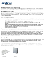
Evaporative Humidifier / Cooler Nortec MH Series
Is a sustainable solution for both humidifying and cooling. Nortec’s MH series is an evaporative humidifier based on the adiabatic
principle that results in air humidifying and cooling. Its innovative design is specifically engineered for Air Handing Units (AHU) or
ventilation duct systems and is a perfect compliment towards GREEN/LEED building design.
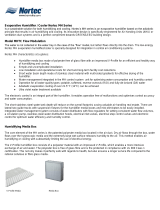
Model MHB Flow On/Off
The water is not collected in the water tray in the case of the “flow” model, but rather flows directly into the drain. The low-energy
Nortec MH evaporation humidifier/cooler is specially designed for integration in central air conditioning systems.
Nortec MH characteristics at a glance:
Humidifier media box made of polyester free of glass fibre with an impressed V-Profile for an efficient and healthy way
of humidifying and cooling
Simple and uncomplicated installation
Low installation and operational costs for short and long-term facility cost reductions
Short water basin depth made of stainless steel material with multi-sided gradients for effective drying of the
humidifier.
Water management integrated in the MH control system unit for optimising water consumption and humidity control
Operation for all water quality types: potable, softened, reverse osmosis (R/O) and fully-de-ionized (D/I) water
Adiabatic evaporation cooling of over 21.5° F (12°C) can be achieved
Ultra violet water treatment available
The electronic control is an integral part of the humidifier. It enables operation free of malfunctions and optimises control accuracy
and water consumption.
The short stainless steel water tank depth will reduce on the overall footprint, saving valuable air handling real estate. There are
lateral two guide tracks with suspension fixtures for the humidifier media boxes and mist eliminators to be easily installed.
Integrated water management system consists of water distributors with flow regulators for setting consistent water flow volumes,
a circulation pump, stainless steel water distribution hoods, electrical inlet valves, electrical step control valves and electronic
control for optimum water efficiency and humidity control.
Humidifying Media Box
The core element of the MH series is the patented polyester media box located in the air duct. Dry air flows through the box, water
flows over the hygroscopic media and the extremely large wet surface releases humidity to the air. This method enables air
humidifying or cooling with substantially limiting the use of electrical energy.
The V-Profile humidifier box consists of a polyester material with an impressed V-Profile, which enables a more intensive
exchange of air and water. The polyester box is free of glass fibre and is fire protected in compliance with UL 900 Class 1
certification. This not only makes it perfectly safe with regards to health, but also ensures a longer service life compared to the
rational cellulose or fibre glass media.
V-Profile Media Media Box

Key benefits of the innovative V-Profile humidifier media box:
Low Pressure Drop
Hygroscopic Coating
UL 900 Class 1 Rating
High Velocity Performance
Suitable for all Water Quality
No Droplets, Free of Aerosols
MHB On/Off Control System
The MH control unit controls the humidity and governs the water management to maximize efficiency. The integrated processor
with real-time clock controls the air humidity, pre-cleaning sequences, unit purging and water quality control, all fully automatically.
The controller is designed for connection to building management systems (BMS). This means that parameters such as
humidifying requirement, water consumption, maintenance requirement or operating hours can be transmitted further via modbus,
LON Talk or BACnet with LINKS2.
The electronic control cabinet includes electrical fusing and main power switch.
One, two or three stage control through magnetic staging valves is available. Microprocessor PI-controlled analog humidity signals
for flexibility. Controlled flushing of the water tank in function of the filling cycles or time controlled drainage through the integrated
real time clock. Programmable wash cycle for cleaning the humidification media. Automatic flushing of the water lines at the end of
a season shutdown or without a call for humidity. An automatic forced drain after shutdown periods longer than 72 hours, an
interruption in humidifying requirement of over 72 hours or in the case of a power failure.
Controller Management System
Key Benefits:
Smart Water Management
Advanced Hygiene Control
Capable of Monitoring & Control via Internet or BMS
Full Functional Operating Panel
Adjustable Flush Cycles
Pre-Cleaning Sequence
Programmable Maintenance
UV Sensing

Available Options and Accessories
UV water treatment
Pressure reduction valve (building side) consult factory
P/N 1329505 - In-Line Water filter c/w 5 micron filter
Nortec On/Off Controls:
P/N 2520273 - On/Off Dig. Duct Humidistat pkg
P/N 2520259 - On/Off Digital Wall Humidistat
P/N 1329203 - Switch Air Proving (duct airflow safety interlock)
Nortec LINKS2 and Nortec Online please consult factory
MHB Flow Technical data
Humidifying output see performance data
Power consumption w/UV 0.30 kW
Power consumption w/o UV 0.20 kW
Primary voltage 120/1/60 V/Ph/Hz
Control voltage 24 Vac On/Off
Water mains pressure 30..145 psi
Water connection 3/4 "
Water drain 1 ½ “
Width/Height/Depth See performance data
Make Nortec
Type MHB Flow
Manufacturer Walter Meier Climate Canada Inc.
14.31
17.61
16.75
12.00
(TC) Total Controller System Mounting Dimensions

MH Wiring Diagram
MH Series (120 Vac)
FLOW INTERNAL WIRING DIAGRAM
Diagram No. 2543942 Rev. A Nov. 25, 2008
X4
X5
X7
N
N
UV Lamp
Drain Valve
Inlet Valve
N
Pump
Res2
Level Max
Level Min/PS
+24V
Res1
X3
+24V
0-10V
GND
Input
GND
X1
5V
X2
24V
5V
Max. Level
X1
0
N
L1
L1
N
X1
1
X9
P
N
P1
L1
N
SC
SC
PT1
PT2
F4
(200
mA)
F1
(6.3 A)
F3
(630
mA)
F2
(1.0 A)
Main Switch
Primary
Terminal
Block
Internal
External
Drain Valve
Inlet Valve
Inlet Water Pressure Switch
Stage 1 Valve
Stage 2 Valve
Stage 3 Valve
X6
N
Stage 3
Stage 2
Stage 1
24 Vac
Security Loop
GND
Channel 1
+5 Vdc
GND
Optional UV Lamp
}
}
ON
Active
}
}
Service
Fault
4
2 3
5
1
L1 N
8 9 1011 1312 1514 17163 4 5
7
61 2
10
9
8
11
14
16
17
1
2
120/24
Vac
Hydraulic Unit
Internal
External
Spare
18
2021 222324 2526
27
6.25A
3 4 6
1
3
R1
1819
12


Installation
Installation of the MH is simple and uncomplicated. The stainless steel water tank and lateral side supports can be integrated into
a ventilation duct or air handling unit very quickly. The media boxes can be mounted in the simplest of manners and only three
connections are needed, the supply inlet water valve, drain water valve and all electrical/control connections. The Flow model
incorporates a 120V single phase connection.
Typical MH installation. Use as reference only. MHTC REflow shown.
/


