Electrolux EFLW427UIW User manual

Category
Washing machines
Type
User manual
1
A11200302 (1803)
USA 1-877-435-3287
This information is intended for Qualified Technicians Only.
TABLE OF CONTENTS
Entering Diagnostic Mode:
1 Press power to turn machine on.
2 Rotate cycle selector ring (on some models) or repeatedly press
cycle button (on other models) to set cycle to normal.
3 Press the start button.
4 Power off machine by pressing the power button.
5 Power on machine by pressing the power button again.
6 Within 10 seconds, simultaneously hold temp + select (set) buttons
together for 3 seconds.
7 Diagnostic Mode is active when LED’s start blinking in sequence.
This is the pre-test position “ ”, which tests the lights and buttons.
Safety items throughout this manual are labeled with a WARNING or
CAUTION based on the risk type as described below:
Washer Tech Data Sheet
Scrolling through Diagnostic Mode tests:
Tests are selected by using the same method to select cycles. See Diag-
nostic Mode Tests Table.
To begin, press and hold the cycles button for 2 seconds. The unit will
advance to the first test; and flash “ ” on the display.
Press the cycles button to advance to the following test. Press the
temp button to go back to the previous test. Test sequence numbers
are briefly displayed when each test is selected. The displayed test num-
bers also correspond to the selector LEDs to the right of the numeric
display; beginning with the top LED, following downward.
Exiting Diagnostic Mode:
Hold the power key for 3 sec, when not in “ ” test step Lights/But-
tons, or unplug the unit.
www.electroluxappliances.com
Canada 1-800-265-8352
Push Button Cycle Select Washer User Interface
Rotary Dial Cycle Select Washer User Interface
This symbol alerts you to situations that may
cause bodily injury or property damage.
This symbol alerts you to situations that may
cause serious body harm, death or property
damage.
CAUTION
WARNING
CAUTION
Unless otherwise directed, disconnect electrical current before
servicing.
Washer Tech Data Sheet ....................................................................... 1
Diagnostic Mode Tests .......................................................................... 2
Demo Mode .......................................................................................... 3
Washer Error Codes .............................................................................. 3
Troubleshooting Tests ............................................................................ 5
Wiring Diagrams .................................................................................. 19
cancel
10
start/pause
10
7
1
power
2
cycle status display
3
cycle selector
4
temperature
5
soil level
6
spin speed
7
options
8
select (set)
9
21 63 854 9 10
2
7
1
6
3 8
54
9
10
11
PODS
®
11
WARNING
The information within this manual is intended for Qualified
Service Technicians Only.
DO NOT reach into the appliance while the tub or drum is
spinning.
Disconnect power before servicing machine.
Certain internal parts are intentionally not grounded and may
present a risk of electric shock only during servicing.
2
Diagnostic Mode Tests
MODE
NUMBER
TEST NAME COMPONENTS UNDER TEST TEST CONDITIONS DISPLAYED FEEDBACK
Lights, Buttons LED indicators
LCD screen
Button response
Number of key pressed.
Note: This number may not
necessarily correspond to key
number on table on page 1.
(select models only)
PODS
®
compartment
(no test for 400 series)
Door lock
PODS
®
valve
Valve stays on until water level reaches
20 liters. Then door remains locked for
5 minutes.*
Water level
Wash compartment Door lock
Hot valve
Valve stays on until water level reaches
140 mm. Then door remains locked for
5 minutes.*
Water level
Bleach compartment Door lock
Bleach valve
Valve stays on until water level reaches
140 mm. Then door remains locked for
5 minutes.*
Water level
Softener compartment Door lock
Prewash valve
Bleach valve
Valve stays on until water level reaches
140 mm. Then door remains locked for
5 minutes.*
Water level
Stain compartment Door lock
Prewash valve
Valve stays on until water level reaches
140 mm. Then door remains locked for
5 minutes.*
Water level
Wash compartment Door lock
Cold valve
Valve stays on until water level reaches
140 mm. Then door remains locked for
5 minutes.*
Water level
Door unlock Drum light Drum light turns on when door is open.
Heater & motor Pressure sensor
Cold valve
Motor
Heater
NTC
Door lock
Drum light
Motor moves after machine fills with
60 mm of water. Heater heats
until temperature reaches 70º C.
Max. duration of test is 8 minutes.
Need power meter to check heater
functionality.
NTC reading
Recirculation Pump
(no test on 400 series )
Recirculation pump
Pressure sensor
Cold valve
Motor
Door lock
Drum light
Motor moves after machine fills with
140 mm of water. Recirculation pump
turns on. Max. duration of the test is 8
minutes.
Display
Concentrate wash pump
(no test on 400 and 500
series)
Concentrate wash pump
Door lock
Drum light
Concentrate wash pump turns on for
max. 5 minutes. Need power meter
to check concentrate wash pump
functionality.
Display
Drain pump & spin Drain pump
Motor
Door lock
Drain pump turns on until empty, then
motor starts spinning at max. rpm for 30
seconds. Then door remains locked for
6 minutes.*
Display (drum speed/10)
All valves on Door lock
All valves
Valve stays on until water level reaches
140 mm. Then door remains locked for
5 minutes.*
water level
Error history The last 3 errors in memory Errors are displayed in order of history
(most recent first).
Note: Pressing temp + select (set)
buttons together clears error history.
precedes the 2 character
alarm code, alternating through
the alarms
* Note for diagnostic mode only: The door is locked in the spin test step, however it can unlock without delay in another test step or on
exiting diagnostic mode, when opening the door the drum can have energy as it spins down.
3
Demo Mode/Washer Error Codes
Washer Error Codes
Demo Mode:
The Demo works in two ways: Interactive Mode and Automatic Loop.
The Interactive Mode enables the customer to use the interface
without activating the appliance. The machine behavior appears similar
to normal operation. With the door closed, pressing start, the appliance
turns on and the display counts down by the second from the maximum
time displayed with its respective cycle. The appliance turns off when it
reaches “ ”.
The Automatic Loop will engage if no one interacts with the user inter-
face for 3 minutes, or the start button hasn’t been pressed. The machine
will simulate a cycle execution on the display only.
Entering Demo Mode:
1 Press power and look for console light up.
2 For Rotary Dial Cycle Select Washer: Within 10 seconds select
fast wash and then simultaneously press and hold temp and select
(set) buttons for 3 secs. Skip to Step 4.
3 For Push Button Cycle Select Washer: Within 10 seconds select
rinse & spin and then simultaneously press and hold temp and
select (set) buttons for 3 secs. Continue to Step 4.
4 The message “ ” will blink 3 times in the center display.
5 If “ ” message does not appear, turn off machine and repeat
previous steps.
Exiting Demo Mode:
To exit Demo Mode, perform the same sequence used to enter Demo
Mode.
1 Press cycles to advance the cycle selection to Delicates.
2 Press start; then Press cancel.
3 Press power to turn the unit off.
4 Press power to turn the unit on. The unit will display will flash “
3 times on the numeric display.
5 Press and hold temp and select (set) simultaneously. The appliance
will beep once, the numeric display will cycle off and on. The appli-
ance will then beep with the normal power on sequence.
You may also perform a Factory Default Reset - see below.
Error
Code
Error Description Display
Notification
Next Step
11 Fill time too long Yes Refer to test (1)
13 Water leak in tub or in pressure sensor No Refer to test (2)
21 Water not pumping out fast enough Yes Refer to test (3)
23 Drain triac error No Refer to test (3)
24 Drain triac error sensing No Refer to test (3)
31 Electronic pressure switch error No Refer to test (4)
32 Pressure sensor calibration problem No Refer to test (4)
35 Pressure sensor indicates water overfill No Refer to test (5)
38 Air trap clogged No Refer to test (5)
41 Control board thinks the door switch is open Yes Refer to test (6)
42 Door lock device failure No Refer to test (6)
43 Door lock triac failure No Refer to test (6)
44 Door closed sensing failure No Refer to test (6)
45 Line door sensing failure No Refer to test (6)
55
(select models)
Motor under speed
(not available on 300 series)
No Check for heavy or unbalanced load
Refer to test (9)
57 High current on inverter (motor control) No Refer to test (8)
58 High current on motor phase No Refer to test (8)
59 No spin signal for 3 seconds No Refer to test (9)
5A High temperature on control due to overload (motor control) No Refer to test (8)
5B Motor control under voltage No Check supply under load and wiring to unit
Refer to tests (6 and 9)
To return to factory settings,
press the soil and options buttons at
the same time and hold until the signal
sounds.
Recalling Last Error Code:
1 Press power and look for console light up.
2 Wait at least 10 seconds, then simultaneously press and hold temp
and select (set) buttons for 3 secs.
3 The display will show the last error in memory.
4 Clear the display and return to normal operation by touching any
button or by pressing the power button.
NOTE
Once Demo Mode is activated, every time the machine is turned on,
Demo Mode is automatically recalled; this occurrence is signaled at
the start-up by the text “ ” flashing 3 times in the center display.
Unplugging the unit will not clear Demo Mode. See “Exiting Demo
Mode” for more information.
Factory Default Reset:
1 Press power and look for console light up.
2 Wait at least 10 seconds, then simultaneously press and hold soil
and options buttons for 3 secs.
Washer Error Codes
4
Washer Error Codes
Error
Code
Error Description Display
Notification
Next Step
5C High Voltage experienced by motor control board No Refer to test (12)
5D Communication problem with motor control (message) No Refer to test (10)
5E Communication problem from motor control (communication failure) No Refer to test (10)
5F MC is continuously resetting No Refer to test (10)
62 Wash temperature too high No Refer to tests (13 and 14)
66
(on select models)
Heater relay problem No Refer to test (14)
68
(on select models)
Current leakage to ground on heater or wiring No Refer to test (14)
69
(on select models)
Heater open No Refer to test (14)
6A
(on select models)
Heater relay sensing problem No Refer to test (14)
71
(on select models)
Drum water NTC failure. (tub heater) No Refer to test (13)
74 Wash temperature does not increase No Refer to tests (13 and 14)
83 Wrong selector reading No Refer to test (10)
84
(on select models)
Recirculation pump triac sensing failure which stops the cycle No Replace main board
85
(on select models)
Recirculation pump triac alarm which stops the cycle No Refer to test (21)
86 Incorrect UI selection table No Refer to test (11)
87 User interface micro-controller fault No Refer to test (11)
88
(on select models)
Concentrated wash pump triac alarm No Refer to test (22)
91 User interface protocol incongruence error Yes Refer to test (11)
92 User interface mother board protocol incongruence No Refer to test (11)
93 Console or main board control problem (incompatible machine
configuration)
Yes Refer to test (11)
94 Main board control problem (incompatible cycle configuration) Yes Refer to test (10)
97 Console or main board control problem (incompatible cycle
configuration)
Yes Refer to test (11)
98 Incompatible motor control/main board No Refer to test (10)
9C User interface configuration problem Yes Refer to test (11)
9E Touch sensor on user interface not responding No Refer to test (20)
H1/B1 Frequency of power out of limits Yes Refer to test (18)
H2/B2 Supply voltage too high (incoming voltage) Yes Refer to test (18)
H3/B3 Supply voltage too high (incoming voltage) Yes Refer to test (18)
HE/BE Control Relay fault No Refer to test (18)
HF/BF Control relay sense fault No Refer to test (18)
F2 Too much soap or wrong type Yes Advise customer to reduce detergent or change to
high efficiency,
type
F5 Load unbalanced No Redistribute load and restart
F6 Control reset No Refer to test (19)
F9 Hot valve warning - hot water and cold water hoses reversed No Reverse the water hoses to reduce the risk of water
temperature related problems with the load
Washer Error Codes, continued
5
Troubleshooting Tests
Test
Number
Check/Test Activity Steps Correction
Test 1 1. Is the incoming water flow normal? Yes, go to step (4).
No, go to step (2).
2. Are the incoming water faucets turned on? No, turn water faucets on.
Yes, go to step (3).
3. Is the incoming water pressure above 20 psi? No, have customer correct pressure problem.
Yes, check for kinked or blocked incoming water hoses, clean the incoming water
screens. If problem still remains, replace the water inlet valve assembly.
4. Does the fill water continue to enter the washer? Yes - Go to step (5)
No - Go to step (6)
5. Remove power from the washer. Did the water fill stop? Yes - Go to step (6)
No - Replace the inlet valve assembly. If pressure switch checks good, go to step
(7). If pressure switch checks bad, replace pressure switch.
6. Replace the pressure sensor. If this did not correct the problem, go to step 7.
7. Replace the main control board.
Test 2 1. Is the washer leaking water? Yes, correct water leak.
No, go to step (2).
2. Is there an air leak in the pressure sensor system? Yes, correct the air leak problem.
No, go to step (3).
3. Replace the pressure sensor. If this did not correct the problem, go to step (4).
4. Replace the main control board.
Test 3 1. Check the drain hose for restrictions. If there is a restriction, correct the problem.
No restriction, go to step (2).
2. Start the washer and check for 120 VAC at the drain pump. If reading zero, check the wiring. If wiring good, replace the main control board.
If reading 120 VAC, remove the pump and check for blockage. If blocked, remove
the restriction, if not, replace the pump.
Test 4 Inspect the wiring between the pressure sensor and the main
control board.
If wiring defective, correct wiring.
If wiring OK, replace pressure sensor. If this does not correct the problem, replace
the main control board.
Test 5 1. Is the water level above 4.5 inches? Yes, go to step (2).
No, go to step (4).
2. Does water enter the washer continuously? Yes, go to step (3).
No, check air trap for clog, if not replace the main control board.
3. Remove power from washer. Does the water stop coming in? No, replace water valve assembly.
Yes, check wiring to valve assembly for shorts. If wiring is good, replace the main
control board.
4. Replace the pressure sensor switch. Did this correct the
problem?
Yes, problem solved.
Test 6 1. Is the loading door closed? No, close the door.
Yes, go the step (2).
2. Can you hear the lock attempt to close? Yes, check the door strike. If good, replace the door
No, go the step (3)
3. Check wire connection between door lock and main control
board.
If good, replace the door lock. Then if problem is not fixed, replace the main
control board.
6
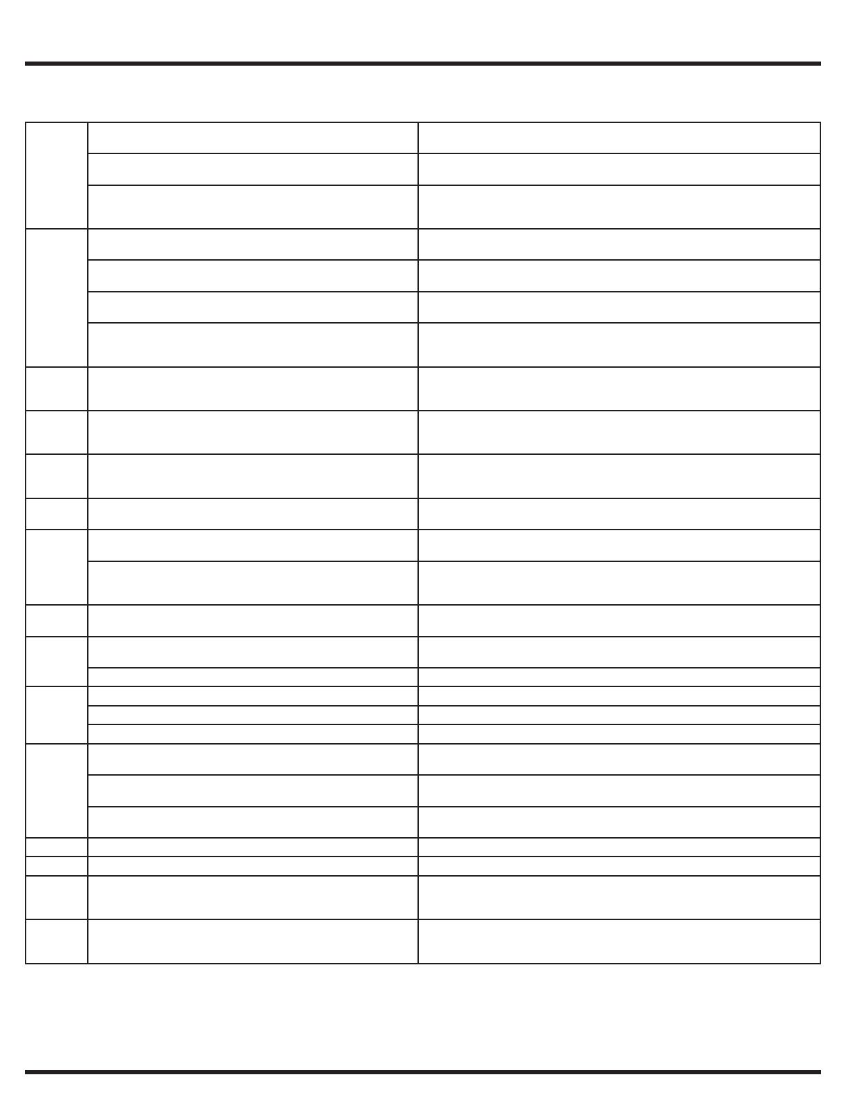
Test 8 1. Find out if the unit was overloaded. If not, remove the belt from
the motor and spin the motor pulley. Does the motor spin free?
No, replace the motor.
Yes, go to step (2).
2. Spin the tub pulley. Does the tub spin free? No, check the tub bearings.
Yes, go to step (3)
3. Disconnect the plug from the motor and measure the resistance
of the windings (pin 1 to pin 2, pin 1 to pin 3, pin 2 to pin 3).
All readings should be between 3 and 6 Ohms.
If the readings are correct, check wiring from motor to motor control board,
If good, replace the motor control board. If the readings are incorrect, replace
the motor.
Test 9 1. Remove the belt from the motor and spin the motor pulley.
Does the motor spin free?
No, replace the motor.
Yes, go to step (2).
2. Spin the tub pulley. Does the tub spin free? No, check the tub bearings.
Yes, go to step (3).
3. Disconnect the plug from the drive motor and measure the
resistance between pins 4 & 5 in the motor.
If the meter reads other than between 105 to 130 Ohms, replace the motor. If the
reading is between 105 to 130 Ohms, go to step (4).
4. Disconnect the plug from the motor and measure the resistance
of the windings (pin 1 to pin 2, pin 1 to pin 3, pin 2 to pin 3). All
readings must be between 3 and 6 Ohms.
If the readings are correct, replace the motor control board.
If the readings are incorrect, replace the motor.
Test 10 Communication problem. Check the wiring between the main
control board and the motor control board.
If wiring is bad, correct wiring problem.
If wiring is good, replace the main control board. If the problem is not corrected,
replace the motor control board.
Test 11 Communication problem. Check the wiring between the main
control board and the user interface board.
If wiring is bad, correct wiring problem.
If wiring is good, replace the user interface board. If the problem is not corrected,
replace the main control board.
Test 12 Have the power company or professional check the frequency and
voltage of the incoming power under load.
If correct, for error code E5C, replace the motor control board.
If correct, for error codes H1/B1, H2/B2, H3/B3, HE/BE, or H5/B5 replace the
main control board
Test 13 Check the resistance of the water NTC. Is it around 4.8K ohms? No, replace the NTC sensor
Yes, check the wiring.
Test 14 1. Check the resistance of the heating element. It should be ap-
proximately 14 ohms.
If the reading is incorrect, replace the heating element.
If the reading is correct, move to the next step.
2. Check the resistance between ground and both heater termi-
nals. It should be open when the heater terminals are discon-
nected.
If the readings are incorrect, replace the heating element. If the problem is not
corrected, check the wiring, If wiring is OK, replace the main control board.
Test 15 Check wiring between the main control board and motor control
board.
If wiring is good, replace the motor control board.
Test 16 1. Are the hot and cold water hoses switched? Yes, switch the hoses to correct position
No, go to step 2
2. Is the HOT water about the same temperature as the cold? Yes, fix the HOT water in the house supply.
Test 17 1. Check wiring between main board and pump. If OK, then go to step (2).
2. Check wiring between main control and recirculation board. If OK, then go to step (3).
3. Check pump for open coil (resistance check). If OK, then replace main control.
Test 18 1. Check power in for voltage under load. Correct supply or branch circuit issues.
No problem go to step 2.
2. Check power wiring to main board. Yes, fix wiring or plug to main board.
No, go to step 3.
3. Check wiring to motor board for short to power or ground. Yes, fix problem.
No, replace the main board.
Test 19 Check wiring to main board. Unplug the unit for 1 minute and retry. If problem is not corrected replace main control.
Test 20 Unplug and re-seat connector between UI boards. If problem persists, replace UI satellite board.
Test 21 Check wiring to recirculation pump If wiring is bad, correct wiring problem.
If wiring is good, replace recirculation pump. If the problem is not corrected,
replace the main control board.
Test 22 Check wiring to concentrated wash pump If wiring is bad, correct wiring problem.
If wiring is good, replace concentrated wash pump. If the problem is not
corrected, replace the main control board.
Washer Troubleshooting Tests, continued
Troubleshooting Tests
19
Wiring Diagram - 427 Series Washer
Schéma de câblage - Laveuse de série 427 | Esquema de cableado - Lavadora Serie 427 (A10860901)
CAUTION
ELECTRICAL SHOCK HAZARD
To avoid electrical shock, disconnect electrical
current before servicing.
ATTENTION
RISQUE DE CHOC ÉLECTRIQUE
Pour éviter tout choc électrique, débranchez le
courant électrique avant l’entretien.
PRECAUCIÓN
PELIGRO DE DESCARGA ELÉCTRICA
Para evitar descargas eléctricas, desconecte la
corriente eléctrica antes de dar servicio.
Wiring Diagrams
Schéma de câblage
Esquema de cableado
20
Wiring Diagram - 527 Series Washer
Schéma de câblage - Laveuse de série 527 | Esquema de cableado - Lavadora Serie 527 (A10861001)
Wiring Diagrams
CAUTION
ELECTRICAL SHOCK HAZARD
To avoid electrical shock, disconnect electrical
current before servicing.
ATTENTION
RISQUE DE CHOC ÉLECTRIQUE
Pour éviter tout choc électrique, débranchez le
courant électrique avant l’entretien.
PRECAUCIÓN
PELIGRO DE DESCARGA ELÉCTRICA
Para evitar descargas eléctricas, desconecte la
corriente eléctrica antes de dar servicio.
21
Wiring Diagram - 627 Series Washer
Schéma de câblage - Laveuse de série 627 | Esquema de cableado - Lavadora Serie 627 (A10860601)
Wiring Diagrams
CAUTION
ELECTRICAL SHOCK HAZARD
To avoid electrical shock, disconnect electrical
current before servicing.
ATTENTION
RISQUE DE CHOC ÉLECTRIQUE
Pour éviter tout choc électrique, débranchez le
courant électrique avant l’entretien.
PRECAUCIÓN
PELIGRO DE DESCARGA ELÉCTRICA
Para evitar descargas eléctricas, desconecte la
corriente eléctrica antes de dar servicio.
  • Page 1 1
  • Page 2 2
  • Page 3 3
  • Page 4 4
  • Page 5 5
  • Page 6 6
  • Page 7 7
  • Page 8 8
  • Page 9 9
  • Page 10 10
  • Page 11 11
  • Page 12 12
  • Page 13 13
  • Page 14 14
  • Page 15 15
  • Page 16 16
  • Page 17 17
  • Page 18 18
  • Page 19 19
  • Page 20 20
  • Page 21 21
  • Page 22 22
  • Page 23 23
  • Page 24 24

Electrolux EFLW427UIW User manual

Category
Washing machines
Type
User manual

Ask a question and I''ll find the answer in the document

Finding information in a document is now easier with AI