Lifetime 90630 Owner's manual

Category
Bicycle accessories
Type
Owner's manual
Watch Our Instructional Videos
Scan the code below to see how it all comes
together.
http://go.lifetime.com/90630videos
TOOLS REQUIRED
TABLE OF CONTENTS
CONTACT LIFETIME CUSTOMER SERVICE:
Call: 1-800-225-3865
7:00 am–5:00 pm (Monday–Friday) MST
and 9:00 am–1:00 pm Saturday MST
QUESTIONS?
MODEL# AND PRODUCT ID
(you will need both when contacting us)
Model Number: 90630
Product ID:
Before you start, prepare a level surface with the proper
Safety Zone (see page 12).
3+ people recommended for setup
Pour le français, voir la page 2. Para el español, ver la página 3.
ASSEMBLY INSTRUCTIONS
MODEL #60091
MODEL 90630
Save this instruction in the event that the manufacturer has
to be contacted for replacement parts.
BEFORE ASSEMBLY:
For Customer Service in Mainland
Europe and the United Kingdom:
Live Chat: www.lifetime.com
(click on “Ask An Expert” tab)
Video Instructions:
www.youtube.com/lifetimeproducts
ADVENTURE TOWER
DELUXE PLAYSET
1/2" (13 mm)
(x2)
(x1)
(x3)
3/8" (10 mm)
(x1)
(x1)
1/2" (13 mm)
(x1)
(x1)
(x1)
3/16" (5 mm)
(x1)
1/4" (7mm)
(x1)
(x1)
(2, included)
5/16" (8 mm)
(x3)
Icon Legend...............................4
Warnings and Notices.................5
Safety Information.....................6
Safe Play Area...........................12
Tower Frame Assembly..............13
Deck Assembly.........................27
Roof Assembly..........................43
Parts Identifi er..........................i-iv
Tower Walls Assembly................49
Climber & Slide Assembly..........60
Monkey Bars Assembly...............68
Swing Bar Assembly..................75
Fire Pole Assembly....................79
Anchor Kit Assembly.................83
Maintenance Instructions..........88
Registration...........................91
Warning Sticker........................92
Warranty..............................93
COPY
5
WARNINGS AND NOTICES / AVERTISSEMENTS ET AVIS / ADVERTENCIAS Y AVISOS
Most injuries are caused by misuse and/or not following instructions. Use caution when using this product.
To ensure safety, do not attempt to assemble this product without following the instructions carefully. Check entire box and inside all packing
material for parts and/or additional instruction material. Before beginning assembly, read the instructions and identify parts using the hardware
identifi er and parts list in this document. Proper and complete assembly, use and supervision are essential for proper operation and to reduce the
risk of accident or injury. A high probability of serious injury exists if this product is not installed, maintained, and operated properly.
FAILURE TO FOLLOW THESE WARNINGS MAY RESULT IN SERIOUS INJURY OR PROPERTY DAMAGE AND WILL VOID WARRANTY.
Owner must ensure that all players know and follow these rules for safe operation of the system.
If using a ladder during assembly, use extreme caution.
Three capable adults are recommended for this operation.
Be aware that parts can be damaged by overtightening the screws.
All who participate in the assembly process should wear safety glasses throughout the assembly.
SAFETY INSTRUCTIONS
La mayoría de las lesiones son causadas por el abuso y/o por el no seguir las instrucciones. Sea cauteloso al usar este producto.
Para su seguridad, no intente ensamblar este producto sin leer y seguir todas las instrucciones cuidadosamente. Revise la caja entera y todos los
materiales de embalaje en busca de piezas y / o material de instrucciones adicional. Antes de comenzar el ensamble, identifi que todas las piezas y el
equipo usando las listas de partes y equipo así como los identifi cadores en este documento. El ensamble correcto y completo, el uso y la supervisión
son esenciales para una orientación apropiada y para reducir el riesgo de un accidente o lesión. Existe una alta probabilidad de sufrir lesiones graves
si este producto no es instalado, mantenido y / o operado correctamente.
EL INCUMPLIMIENTO DE SEGUIR ESTAS ADVERTENCIAS PUEDE OCASIONAR EN LESIONES GRAVES Y/O DAÑO A LA PROPIEDAD Y ANULARÁ LA GARANTÍA.
El propietario debe asegurarse de que todos los jugadores conocen y seguir estas reglas para la operación segura del sistema.
Si utiliza una escalera durante el ensamble, tenga mucho cuidado.
Se recomienda la participación de tres adultos capaces para esta ensamble.
Es posible endañar las piezas por apretar demasiado los tornillos.
Todas las personas que participan en el ensamble deben llevar gafas de segurdad a lo largo del ensamble.
INSTRUCCIONES DE SEGURIDAD
La majorité des accidents résultent d’une mauvaise utilisation et/ou du fait de n’avoir pas suivi les consignes. Observez toutes précautions utiles pendant
l’utilisation de ce produit.
Pour assurer votre sécurité, ne tentez pas d’assembler cet article sans avoir lu et suivi toutes les consignes attentivement. Vérifi ez la totalité de la
boîte et l’intérieur de tous les matériaux d’emballage pour trouver toutes les pièces et/ou matériau contenant des consignes supplémentaires. Avant
de commencer le montage, identifi ez toutes les pièces et tous les accessoires et faites-en l’inventaire en les comparant aux listes et identifi cateurs
de pièces et accessoires contenus dans ce document. Un assemblage correct et complet, ainsi que l’utilisation et la supervision correctes sont des
conditions essentielles à la bonne direction et diminuent les risques d’accident ou de blessure. Une haute probabilité d’accident grave résulte de
mauvaises conditions d’installation, maintenance et/ou utilisation.
LE NON-RESPECT DE CES AVERTISSEMENTS PEUT RÉSULTER EN ACCIDENTS GRAVES OU DOMMAGES MATÉRIELS ET ANNULER LA GARANTIE.
Le propriétaire doit veiller à ce que tous les joueurs connaissent et suivent ces règles pour une exploitation sûre du système.
Agissez avec la plus grande prudence si vous employez une échelle pour l’assemblage.
Il est recommandé que cet assemblage soit exécuté par trois personnes adultes.
Il est possible d’endommager les pièces en serrant les vis excessivement.
Toutes les personnes qui participent à l’assemblage doivent porter des lunettes de sécurité tout le long de l’assemblage.
CONSIGNES DE SÉCURITÉ
6
IMPORTANT SAFETY INFORMATION
Place the equipment on a level, well-drained ground, not less than 6.6 ft (2.0 m) from any structure
or obstruction such as a fence, garage, house, overhanging branches, laundry lines, or electrical wires.
Provide enough room so that children can use the equipment safely. For example, for structures with
multiple play activities, a slide should not exit in front of a swing.
Separate active and quiet activities from each other. For example, locate sandboxes away from swings
or use a guardrail or barrier to separate the sandbox from the movement of the swings.
Do not install home playground equipment over concrete, asphalt, packed earth, grass, carpet, or
any other hard surface. A fall onto a hard surface can result in serious head injury or death. (see page
7).
To prevent serious injury, warn children that they must not use the equipment until properly installed.
Create a site free of obstacles that could cause injuries – such as low overhanging tree branches,
overhead wires, tree stumps and/or roots, large rocks, bricks, and concrete.
Choose a level location for the equipment. This can reduce the likelihood of the play set tipping over
and loose-fi ll surfacing materials washing away during heavy rains.
For any questions call our Customer Service Department at 1-800-225-3865 for more information.
INSTALLATION & GROUND PREPARATION INSTRUCTIONS
OPERATING INSTRUCTIONS
Observing the following instructions and warnings reduces the likelihood of serious or fatal injury:
The maximum number of occupants that may safely use the entire play set including all
components is ten with a maximum weight of 1600 pounds (727 kg).
On-site adult supervision should be provided for children of all ages.
Instruct children not to walk close to, in front of, behind, or between moving items.
Do not move the equipment while it is in use.
Instruct children not to twist swing chains or ropes or loop them over the top support bar since this
may reduce the strength of the chain or rope.
Instruct children to avoid swinging empty seats.
Teach children to sit in the center of the swings with their full weight on the seats.
Instruct children not to use the equipment in a manner other than intended.
Instruct children not to get off the equipment while it is in motion.
To prevent entanglement and strangulation, dress children appropriately using well-fi tting shoes
and avoiding ponchos, scarves, jackets with neck drawstrings, cord-connected items, helmets with
straps, and other loose-fi tting clothing that is potentially hazardous while using equipment. These
items can cause death by strangulation.
Instruct children not to play when the equipment is wet.
Instruct children not to attach items to the playground equipment that are not specifi cally designed
for use with the equipment, such as, but not limited to, jump ropes, clothesline, pet leashes, cables
and chain as they may cause a strangulation hazard.
Dress children with well-fi tting and full foot enclosing footwear. Examples of inappropriate foot ware are
clogs, fl ip ops, and sandals.
• Instruct children to remove their bike or other sports helmet before playing on the playground
equipment. These items can cause death by strangulation.
Instruct children not to twist swing chains or ropes or loop them over the top support bar since this may
reduce the strength of the chain or rope.
Check that suspended climbing ropes, chain, or cable are secured at both ends
Place the equipment no less than 6.6 ft. (2.0 m) from any structure or obstruction such as a fence,
garage, house, overhanging branches, laundry lines, or electrical wires.
Impact surfacing needs to cover the entire recommended play area.
PLEASE READ BEFORE BEGINNING ASSEMBLY
7
*This information has been extracted from the CPSC publications “Playground Surfacing--Technical Information Guide” and
“Handbook for Public Playground Safety.” Copies of these reports can be obtained by sending a postcard to the: Offi ce of
Public Affairs, U.S. Consumer Product Safety Commission, Washington, D.C., 20207 or call the toll-free hotline: 1-800-638-
2772.
***This data is from tests conducted by independent testing laboratories on a 6-inch depth of uncompressed shredded tire
samples produced by four manufacturers. It is recommended that persons seeking to install shredded tires as a protective surface
request test data from the supplier showing the critical height of the material when it was tested in accordance with ASTM F1292.
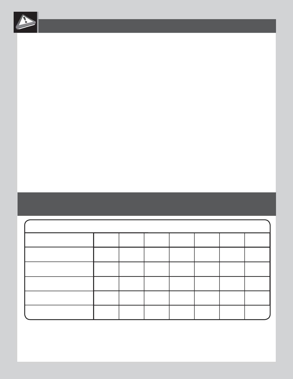
CONSUMER INFORMATION SHEET FOR PLAYGROUND SURFACING MATERIALS*
**The maximum fall height for this product is 90 in (229 cm).
We recommend using 9 in (23 cm) of Double Shredded Bark Mulch.**
5 ft 6 ft 7 ft 9 ft 10 ft 11 ft 12 ft
-- 6 in -- -- 9 in 12 in --
-- 6 in 9 in -- -- -- 12 in
6 in -- 9 in 12 in -- -- --
-- 6 in 9 in -- 12 in -- --
-- -- -- -- 6 in -- --
TABLE 1 — Depth of Surfacing Material Required Based on Fall Heights
Material / Fall Height
Double Shredded Bark
Mulch
Wood Chips
Fine Sand
Fine Gravel
Shredded Tires***
(152 cm)
(183 cm) (213 cm)
(274 cm)
(305 cm) (335 cm) (366 cm)
(15 cm)
(23 cm) (30 cm)
(15 cm) (23 cm) (30 cm)
(30 cm)
(23 cm)(15 cm)
(15 cm)
(23 cm)
(30 cm)
(15 cm)
Select Protective Surfacing—One of the most important things you can
do to reduce the likelihood of serious head injuries is to install shock-
absorbing protective surfacing under and around your play equipment.
The protective surfacing should be applied to a depth that is suitable for
the equipment height in accordance with ASTM Specifi cation F1292.
There are different types of surfacing to choose from; whichever product
you select, follow these guidelines:
Loose-Fill Materials—Maintain a minimum depth of 9 inches of loosefi ll
materials such as wood mulch/chips, engineered wood fi ber (EWF), or
shredded/recycled rubber mulch for equipment up to 8 feet high; and
9 inches of sand or pea gravel for equipment up to 5 feet high. NOTE:
An initial fi ll level of 12 inches will compress to about a 9-inch depth
of surfacing over time. The surfacing will also compact, displace, and
settle, and should be periodically refi lled to maintain at least a 9-inch
depth.
Use a minimum of 6 inches of protective surfacing for play equipment
less than 4 feet in height. If maintained properly, this should be
adequate. (At depths less than 6 inches, the protective material is too
easily displaced or compacted.)
NOTE: Do not install home playground equipment over
concrete, asphalt, or any other hard surface. A fall onto a hard surface
can result in serious injury to the equipment user. Grass and dirt are not
considered protective surfacing because wear and environmental factors
can reduce their shock absorbing effectiveness. Carpeting and thin mats
are generally not adequate protective surfacing. Ground level equipment
– such as a sandbox, activity wall, playhouse or other equipment that has
no elevated play surface – does not need any protective surfacing.
Use containment, such as digging out around the perimeter and/or lining
the perimeter with landscape edging. Don’t forget to account for water
drainage.
Check and maintain the depth of the loose-fi ll surfacing material. To
maintain the right amount of loose-fi ll materials, mark the correct level
on play equipment support posts. That way you can easily see when to
replenish and/or redistribute the surfacing.
Do not install loose fi ll surfacing over hard surfaces such as concrete or
asphalt.
Poured-In-Place Surfaces or Pre-Manufactured
Rubber Tiles—You may be interested in using surfacing other than loose-
ll materials – like rubber tiles or poured-in-place surfaces.
Installations of these surfaces generally require a professional and are
not “do-it-yourself” projects.
Review surface specifi cations before purchasing this type of surfacing.
Ask the installer/manufacturer for a report showing that the product has
been tested to the following safety standard: ASTM F1292 Standard
Specifi cation for Impact Attenuation of Surfacing Materials within the
Use Zone of Playground Equipment. This report should show the specifi c
height for which the surface is intended to protect against serious head
injury. This height should be equal to or greater than the fall height –
vertical distance between a designated play surface (elevated surface
for standing, sitting, or climbing) and the protective surfacing below – of
your play equipment.
Check the protective surfacing frequently for wear.
Placements—Proper placement and maintenance of protective surfacing
is essential. Be sure to:
Extend surfacing at least 6.6 feet (2 m) from the equipment in all
directions.
For to-fro swings, extend protective surfacing in front of and behind the
swing to a distance equal to twice the height of the top bar from which
the swing is suspended.
For tire swings, extend surfacing in a circle whose radius is equal to
the height of the suspending chain or rope, plus 6.6 feet (2 m) in all
directions.
12
Dimensions du Jeu:
16’ 2” (5 m) x 19’ 6” (6 m)
Aire de jeu recommandée:
32' 6" (9,9 m) x 33' 3" (10,1 m)
Dimensiones del conjunto de juegos
16' 2" (5 m) x 19' 6" (6 m)
Área de juego recomendada
32' 6" (9,9 m) x 33' 3" (10,1 m)
Playset dimensions:
16' 2" (5 m) x 19' 6" (6 m)
Recommended play area:
32' 6" (9,9 m) x 33' 3" (10,1 m)
ZONE DE SÉCURITÉ — Placez l’équipement à plus de 2 m (6.6 pi) de toute structure ou obstruction telle
qu’une clôture, un garage, une maison, des branches basses, des cordes à linge ou des fi ls électriques.
Assurez-vous que l’espace libre devant et derrière les balançoires soit d’au moins deux fois la hauteur de
la barre de la balançoire. La surface d’impact doit couvrir l’aire de jeu recommandée au complet. Veuillez
vous référer à l’exemple ci-dessous.
ZONA DE SEGURIDAD — Coloque el equipo a no menos de 2 m (6.6 pies) de cualquier estructura u ob-
strucción como una cerca, una cochera, una casa, ramas que cuelgan, lazos para tender ropa o cables
eléctricos. Asegúrese de que el espacio libre enfrente y detrás de los columpios es de al menos el doble
de la altura de la barra de los columpios. El revestimiento superfi cial de impacto necesita cubrir el área
entera de juego recomendada. Consulte al ejemplo a continuación.
SAFE PLAY AREA / ZONE DE SÉCURITÉ / ZONA DE SEGURIDAD
SAFETY ZONE —
Place the equipment no less than 6.6 ft. (2 m) from any structure or obstruction such
as a fence, garage, house, overhanging branches, laundry lines, or electrical wires. Make sure the clear-
ance in front of and behind the swings is at least twice the height of the swing bar. The impact surfacing
needs to cover the entire recommended play area. Refer to the example below.
32’ 6”
9,9 m
33’ 3”
10,1 m
16’ 11”
5,2 m
6’ 6”
2,0 m
19’6”
6 m
16’ 2”
5 m
16’ 11”
5,2 m
14
3/16 in/po (≈5 mm) 1/2 in/po (≈ 13 mm)
(2)
(2)
TOWER FRAME ASSEMBLY / ASSEMBLAGE DE LA TOUR / ENSAMBLE DE LA TORRE
PARTS REQUIRED / PIÈCES REQUISES / PIEZAS REQUERIDAS
DWU (x4)
DXE (x4)
1
TOOLS REQUIRED / OUTILS REQUIS / INSTRUMENTAL REQUERIDO
(1)
CONTENTS OF BOX 1 / CONTENU DE LA BOÎTE 1 / CONTENIDO DE LA CAJA 1
DWT (x1)
DWS (x2)
DWZ (x8)
CONTENTS OF BOX 2 / CONTENU DE LA BOÎTE 2 / CONTENIDO DE LA CAJA 2
DZO (x4) DWR (x4)
ELR
Parts Bag / Sac des pièces / Bolsa de piezas
DWY (x3)
DXB (x1)
WARNING
nc
6
-0010
www.lifetime.com
ADVE
V
ERTISSEMENT
I
NTENDED FOR THE USE BY CHILDREN FROM
D
IS FOR RESIDENTIAL USE ONLY. Do not
e
te, asphalt, packed earth, or any other
l
l onto a hard surface can result in serious
w
ing statements and warnings reduces the
s
or fatal injury:
p
ervision should be provided for children of
not walk close to, in front of, behind, or
e
ms.
not to twist swing chains or ropes or loop
s
upport bar since this may reduce the
a
in or rope.
to avoid swinging empty seats.
o
sit in the center of the swings with their full
s
. Never stand or kneel on the swing seat.
• Instruct children not t
o
other than intended.
• Instruct children not t
o
motion.
• To prevent entanglem
e
children appropriately u
s
avoiding ponchos, scarv
helmets with straps, an
d
potentially hazardous w
h
• Instruct children not t
o
• Instruct children not t
o
equipment that are not
s
the equipment, such as
,
clothesline, pet leashes,
cause a strangulation h
a
• Make sure guardrails
a
ESTE PRODUCTO ES PAR
A
ESTE PRODUCTO ES SÓL
O
instale sobre concreto,
a
cualquier otra superfici
e
dura podría ocasionar serias lesiones.
Si se presta atención a los si
g
se reduce la probabilidad de
p
• Los niños de todas la
s
supervisión de un adult
o
• Los niños no deben c
a
o entre las piezas móvil
e
• Indique a los niños n
o
columpios ni pasarlas p
superior, ya que puede
cadenas o sogas, segú
n
• Indique a los niños ev
• Enseñe a los niños a
s
columpios, con todo su
pararse ni hincarse en
e
• Indique a los niños n
o
diferente a la indicada.
• Indique a los niños n
o
movimiento.
• Para evitar la posibilid
y estrangulen, vístalos
d
debidamente ajustados
chamarras con cordon
e
con correas y otras rop
a
peligrosas al usar el eq
u
• Indique a los niños n
o
equipo.
• Indique a los niños n
o
juegos objetos no diseñ
a
como cuerdas de saltar,
correas de mascotas, c
a
causar un peligro de es
t
• Asegúrese de que los
en su lugar todo el tiem
N
ÇU POUR UN USAGE PAR DES ENFANTS ÂGÉS
R
ODUIT EST RÉSERVÉ SEULEMENT À UN USAGE
i
nstaller sur du béton, de l’asphalte, de la terre
autre surface dure. Une chute sur une surface
d
es blessures graves.
c
larations et des avertissements suivants réduit
u
res graves ou fatales:
adulte surveillant les enfants de tous âges
e
s enfants ne marchent pas près, devant,
s éléments en mouvement.
e
s enfants ne tordent pas les chaînes ou
ç
oire. De même, veiller à ce que les enfants
s
chaînes ou les cordes au-dessus de la
u
périeure, car cela pourrait en réduire leur
s enfants ne balancent pas les sièges vides.
s enfants s’assoient au centre des sièges de
l
eur plein poids sur le siège. Ne jamais rester
e
à genoux sur le siège de la balançoire.
e
s enfants n’utilisent pas l’équipement à
o
ur l’usage prévu.
e
s enfants ne descendent pas de
u
’il est encore en mouvement.
m
êlement des cordes et des chaînes et
q
ue d’étranglement, veiller à habiller les
e
nt. Utiliser des souliers bien adaptés. Ne
n
chos, foulards, blousons avec des cordons
u
es avec des sangles et tout autre vêtement
e
ntiellement s’avérer dangereux lors de
ipement.
e
s enfants ne grimpent pas sur
d
celui-ci est mouillé.
t
tacher d’objets sur l’équipement de jeu
n
t conçus pour cet équipement, tels que,
e
r, cordes à sauter, cordes à linge, laisses
e
t chaînes. Ceux-ci posent un risque
s
garde-fous sont en place en tout temps.
8 1/2 x 5 1/2
!
!
! !
ELT
Parts Bag / Sac des pièces / Bolsa de piezas
15
TOOLS AND HARDWARE REQUIRED / OUTILS ET QUINCAILLERIE REQUIS / INSTRUMENTAL Y HERRAJE REQUERIDOS
X SECTION 1 (CONTINUED) / SECTION 1 (SUITE) / SECCIÓN 1 (CONTINUACIÓN)
6
ASI (x1) AAN (x1)
DWU
DWS
DWS
AAN
ASI
DWU
1.1
• The dimpled holes on the Angled Deck Supports (DWU)
face downward.
• Les trous cabossés sur les Supports angulaires à pont
(DWU) donnent vers le bas.
• Los agujeros abollados en los Soportes angulares para la
cubierta (DWU) dan hacia abajo.
!
Ensure you orient the Short Deck Support Tube (DWS) as shown. Attach two Angled Deck Supports (DWU) to the Small
Deck Support Tube.
Assurez-vous d’orienter le Tube court de support à pont (DWS) comme illustré. Attachez deux Supports angulaires à pont
(DWU) au Tube court de support à pont.
Asegúrese de orientar el Tubo corto de soporte para la cubierta (DWS) como se muestra. Sujete dos Soportes angulares
para la cubierta (DWU) al Tubo corto de soporte para la cubierta.
http://go.lifetime.com/towerframeassembly
• If you have trouble with this section, scan the code below to view a video on how to assemble the Tower Frame.
Si vous avez des problèmes avec cette section, scannez le code en bas pour voir un vidéo de l’assemblage de la Tour.
• Si tiene problemas con esta sección, escanee el código abajo para ver un video del ensamble de la Torre.
3/16 in/po (≈5 mm)
1/2 in/po (≈ 13 mm)
(2)
(2)
16
TOOLS AND HARDWARE REQUIRED / OUTILS ET QUINCAILLERIE REQUIS / INSTRUMENTAL Y HERRAJE REQUERIDOS
X SECTION 1 (CONTINUED) / SECTION 1 (SUITE) / SECCIÓN 1 (CONTINUACIÓN)
6
ASI (x5) AAN (x5)
AAN
AAN
AAN
AAN
ASI
ASI
ASI
ASI
DWT
DWS
DWS
DWU
DWU
DWU
DWU
1.2
Repeat step 1.1 to attach the remaining two Angled Deck Supports (DWU) to the second Small Deck Support Tube (DWS).
Répétez l’étape 1.1 pour attacher les deux Supports angulaires (DWU) au deuxième Tube court de support (DWS).
Repita el paso 1.1 para sujetar los dos Soportes angulares (DWU) restantes al segundo Tubo corto de soporte (DWS).
1.3
• The holes shown below on the Main Deck Support (DWT) should be oriented so they are closer to the top edge of the Tube.
• Orientez le Support principal du pont (DWT) de sorte pour que les trous (illustrés en bas) soient plus près le bord supérieur du
Tube.
• Oriente los agujeros en el Soporte principal de la cubierta (DWT) (ilustrados abajo) para que estén más cercanos al borde
superior del Tubo.
• The dimpled holes on the Angled Deck Supports (DWU)
face downward.
• Les trous cabossés sur les Supports angulaires à pont
(DWU) donnent vers le bas.
• Los agujeros abollados en los Soportes angulares para la
cubierta (DWU) dan hacia abajo.
!
AAN ASI
The dimpled holes on the Angled Deck Supports
(DWU) face downward.
Les trous cabossés sur les Supports angulaires à
pont (DWU) donnent vers le bas.
Los agujeros abollados en los Soportes angulares
para la cubierta (DWU) dan hacia abajo.
!
3/16 in/po (≈5 mm)
1/2 in/po (≈ 13 mm)
(2)
(2)
19
TOOLS AND HARDWARE REQUIRED / OUTILS ET QUINCAILLERIE REQUIS / INSTRUMENTAL Y HERRAJE REQUERIDOS
X SECTION 1 (CONTINUED) / SECTION 1 (SUITE) / SECCIÓN 1 (CONTINUACIÓN)
AUH (x1)
AAN (x1)
1.7
AAN
AUH
3/16 in/po (≈5 mm)
1/2 in/po (≈ 13 mm)
(2)
(2)
20
TOOLS AND HARDWARE REQUIRED / OUTILS ET QUINCAILLERIE REQUIS / INSTRUMENTAL Y HERRAJE REQUERIDOS
X SECTION 1 (CONTINUED) / SECTION 1 (SUITE) / SECCIÓN 1 (CONTINUACIÓN)
ARL
ARL (x1)
6
DWZ
AUH
AAN
DWZ
DXB
AUH (x1) AAN (x1)
Only fi nger-tighten this hardware at this time.
Ne serrez ces Quincaillerie qu’à la main en ce moment.
Apriete este herraje sólo a mano en este momento.
1.8
21
TOOLS AND HARDWARE REQUIRED / OUTILS ET QUINCAILLERIE REQUIS / INSTRUMENTAL Y HERRAJE REQUERIDOS
X SECTION 1 (CONTINUED) / SECTION 1 (SUITE) / SECCIÓN 1 (CONTINUACIÓN)
6
DWZ
DWZ
AAN
ARX
ARX
AAN
AAN (x2)
ARX (x2)
• Bend the Braces (DWZ) toward the Deck Frame to align the holes. The Braces are designed to be bent by hand.
• Pliez les Supports (DWZ) vers la Charpente du pont, et alignez les trous. Vous pouvez plier les Supports a la main.
• Doble los Soportes (DWZ) hacia el Armazón de la cubierta, y alinee los agujeros. Su puede doblar los Soportes a mano.
Secure the inside Brace fi rst.
Attachez bien le Support intérieur en premier.
Sujete el Soporte interior primero.
Secure the outside Brace second.
Ensuite attachez bien le Support extérieur.
Ensuite sujete el Soporte exterior.
1
2
• Tighten all hardware now.
• Serrez bien tous les Quincaillerie
maintenant.
• Apriete todo el herraje ahora.
1
!
!
2
1.9
3/16 in/po (≈5 mm)
1/2 in/po (≈ 13 mm)
(2)
(2)
22
TOOLS AND HARDWARE REQUIRED / OUTILS ET QUINCAILLERIE REQUIS / INSTRUMENTAL Y HERRAJE REQUERIDOS
X SECTION 1 (CONTINUED) / SECTION 1 (SUITE) / SECCIÓN 1 (CONTINUACIÓN)
6
DWY
AAN
AUH
DZO
AUH (x3)
AAN (x3)
• Secure Foot Caps (DZO) to the three remaining Tower Poles (DWY) with the hardware indicated. Make sure the end of the
Pole with the small notch remains open.
• Attachez les Capuchons inférieurs (DZO) aux Poteaux de support à tour (DWY) restants à l’aide des Quincaillerie indiqués.
Assurez-vous que l’extrémité du Poteau avec la petite encoche reste ouvert.
• Sujete los Tapones inferiores (DZO) a los Varales de soporte para la torre (DWY) restantes usando el herraje indicado.
Asegúrese que el extremo del Varal avec la muesca pequeña queda abierto.
DWYDWY
Notch
Encoche
Muesca
1.10
3/16 in/po (≈5 mm)
1/2 in/po (≈ 13 mm)
(2)
(2)
23
TOOLS AND HARDWARE REQUIRED / OUTILS ET QUINCAILLERIE REQUIS / INSTRUMENTAL Y HERRAJE REQUERIDOS
X SECTION 1 (CONTINUED) / SECTION 1 (SUITE) / SECCIÓN 1 (CONTINUACIÓN)
AUH (x3)
BTS
DXZ
AUH
BTS (x1)
DXZ (x1)
DWY
AAN (x3)
AAN
AAN
ARL
ARL
AUH
DWZ
AAN
DWZ
AUH
Only fi nger-tighten this hardware until further instructed.
Ne serrez pas complètement ces Quincaillerie jusqu’à ce qu’il soit demandé des serrer.
No apriete por completo este herraje hasta que se le indique.
1.12
• Make sure the Angled Deck Supports (DWU) are oriented as shown, closer to the top of the Tower Pole (DWY), with the dimpled
holes on the Angled Deck Supports facing downward, toward the Foot Cap (DXB).
• Assurez-vous d’orienter les Supports angulaires à pont (DWU) comme illustré, plus près l’extrémité supérieure du Poteau de la
tour (DWY), avec les trous cabossés dans les Supports angulaires à pont facing vers le bas, vers le Capuchon inférieur (DXB).
• Asegúrese de orientar los Soportes angulares para la cubierta (DWU) como se muestra, más cercanos al extremo superior
del Varal de soporte para la torre (DWY), con los agujeros abollados en los Soportes angulares para la cubierta dando hacia
abajo, hacia el Tapón inferior (DXB).
Notch should face deck.
L’encoche doit donner
vers le pont.
La muesca debe dar hacia
la cubierta.
ARL (x3)
1.11
DWU
DWU
DWU
DWU
3/16 in/po (≈5 mm)
1/2 in/po (≈ 13 mm)
(2)
(2)
24
TOOLS AND HARDWARE REQUIRED / OUTILS ET QUINCAILLERIE REQUIS / INSTRUMENTAL Y HERRAJE REQUERIDOS
X SECTION 1 (CONTINUED) / SECTION 1 (SUITE) / SECCIÓN 1 (CONTINUACIÓN)
ARX (x6)
AAN (x12)
1.13
• Tighten all hardware now.
• Serrez bien tous les Quincaillerie
maintenant.
• Apriete todo el herraje ahora.
!
AAN
AAN
ARX
ARX
1
2
• Bend the Braces (DWZ) toward the Deck Frame to align the
holes. The Braces are designed to be bent by hand.
• Pliez les Supports (DWZ) vers la Charpente du pont, et
alignez les trous. Vous pouvez plier les Supports a la main.
• Doble los Soportes (DWZ) hacia el Armazón de la cubierta, y
alinee los agujeros. Su puede doblar los Soportes a mano.
1
Secure the inside Brace fi rst.
Attachez bien le Support intérieur
en premier.
Sujete el Soporte interior primero.
Secure the outside Brace second.
Ensuite attachez bien le Support
extérieur.
Ensuite sujete el Soporte exterior.
!
2
• Repeat Steps 1.11, 1.12 and 1.13 to
attach the two remaining Tower Poles (DWY)
to the Deck assembly, then tighten all
hardware.
• Répétez les étapes 1.11, 1.12 et 1.13
pour attacher les deux Poteaux de support
(DWY) restants au Montage du pont,
ensuite serrez bien tous les quicaillerie.
• Repita los pasos 1.11, 1.12 y 1.13 para
sujetar los dos Postes de soporte (DWY)
restantes al Conjunto de la cubierta,
entonces apriete todo el herraje.
1.14
AUH (x6)
BTS (x2)
DXZ (x2)
ARL (x6)
3/16 in/po (≈5 mm)
1/2 in/po (≈ 13 mm)
(2)
(2)
25
TOOLS AND HARDWARE REQUIRED / OUTILS ET QUINCAILLERIE REQUIS / INSTRUMENTAL Y HERRAJE REQUERIDOS
X SECTION 1 (CONTINUED) / SECTION 1 (SUITE) / SECCIÓN 1 (CONTINUACIÓN)
DXE
DXE
DXE
BTS
BTS
DXZ
DXZ
DXB
DWY
DXE
BTS (x2)
DXZ (x2)
1.15
Warning Sticker
Autocollant d’avertissement
Etiqueta adhesiva de advertencia
3/16 in/po (≈5 mm)
(2)
26
TOOLS AND HARDWARE REQUIRED / OUTILS ET QUINCAILLERIE REQUIS / INSTRUMENTAL Y HERRAJE REQUERIDOS
X SECTION 1 (CONTINUED) / SECTION 1 (SUITE) / SECCIÓN 1 (CONTINUACIÓN)
DXZ
DXZ
DXE
BTS
BTS
BTS (x2)
DXZ (x2)
DWR
DWR
DWR
DWR
DWR
Align the holes in the Pole Caps (DWR) with the holes in the Tower Poles, and insert the Caps.
Alignez les trous dans les Capuchons supérieurs (DWR) avec ceux dans l’extrémités des Poteaux de support de la tour,
et insérez les Capuchons.
Alinee los agujeros en los Tapones superiores (DWR) con ellos en los extremos de los Postes de soporte del torre, e
inserte los Tapones.
1.16
1.18
1.17
• No hardware is used for this step.
The Pole Caps will be secured to the
Poles later in the assembly.
• Aucun accessoire est utilisé dans
cette étape. Vous attacherez bien
les Capuchons plus tard.
No se usa ningún herraje en este paso.
Se sujetarán los Tapones más tarde.
!
3/16 in/po (≈5 mm)
(2)
(1)
27
Hardware Blister Pack / Blister de quincaillerie / Blíster de herraje
HARDWARE REQUIRED / QUINCAILLERIE REQUISE / HERRAJE REQUERIDO
PARTS REQUIRED / PIÈCES REQUISES / PIEZAS REQUERIDAS
DXX (x16)
CVZ (x10)
ARN (x6)
DYB (x2) DYC (x2)
BTS (x38)
DXS (x12)
AAN (x8)
DYH
2
EBY
Hardware Blister Pack / Blister de quincaillerie / Blíster de herraje
CUZ (x12)
DXZ (x10)
DECK ASSEMBLY / ASSEMBLAGE DE LA PLATE-FORME / ENSAMBLE DE LA CUBIERTA
CONTENTS OF BOX 2 / CONTENU DE LA BOÎTE 2 / CONTENIDO DE LA CAJA 2
ARL (x18)
AUH (x2)
BZK (x2)
ARL (x2)
LARGE PLASTIC PARTS / GRANDES PIÈCES EN PLASTIQUE / PIEZAS GRANDES DE PLÁSTICO
28
PARTS REQUIRED / PIÈCES REQUISES / PIEZAS REQUERIDAS
TOOLS REQUIRED / OUTILS REQUIS / INSTRUMENTAL REQUERIDO
DZS (x4)
DZT (x1) DZU (x1)
EBT (x4)
3/16 in/po (≈5 mm)
(2)
DXO (x2)
DZV (x2)
DXF (x4) DYA (x4)
DZW (x2)
DXI (x2)
A
B
3/8 in/po (≈10 mm)
(1)
DECK ASSEMBLY / ASSEMBLAGE DE LA PLATE-FORME / ENSAMBLE DE LA CUBIERTA
2
(1)
1/2 in/po (≈13 mm)
(1)
(x1)
CONTENTS OF BOX 2 / CONTENU DE LA BOÎTE 2 / CONTENIDO DE LA CAJA 2
Parts Bag / Sac de pièces / Bolsa de piezas
ELS
CONTENTS OF BOX 1 / CONTENU DE LA BOÎTE 1 / CONTENIDO DE LA CAJA 1
30
TOOLS AND HARDWARE REQUIRED / OUTILS ET QUINCAILLERIE REQUIS / INSTRUMENTAL Y HERRAJE REQUERIDOS
X SECTION 2 (CONTINUED) / SECTION 2 (SUITE) / SECCIÓN 2 (CONTINUACIÓN)
DYB
DYB
DYB
• Slide the Deck (DYB) onto the Deck Frame at an angle, then lower the Deck into position. Repeat for the other side.
• Glissez le pont (DYB) à un angle sur la charpente, ensuite abaissez-le en place. Répétez cette étape pour l’autre côté.
• Deslice la cubierta (DYB) hacia el bastidor de la cubierta en un ángulo y, a continuación, baje la cubierta hacia su
posición. Repita para los otros lados.
2.2
31
TOOLS AND HARDWARE REQUIRED / OUTILS ET QUINCAILLERIE REQUIS / INSTRUMENTAL Y HERRAJE REQUERIDOS
X SECTION 2 (CONTINUED) / SECTION 2 (SUITE) / SECCIÓN 2 (CONTINUACIÓN)
DXZ (x2)
CVZ (x2)
BTS (x2)
DXZ
DXZ
CVZ
CVZ
BTS
BTS
2.3
3/16 in/po (≈5 mm)
(2)
  • Page 1 1
  • Page 2 2
  • Page 3 3
  • Page 4 4
  • Page 5 5
  • Page 6 6
  • Page 7 7
  • Page 8 8
  • Page 9 9
  • Page 10 10
  • Page 11 11
  • Page 12 12
  • Page 13 13
  • Page 14 14
  • Page 15 15
  • Page 16 16
  • Page 17 17
  • Page 18 18
  • Page 19 19
  • Page 20 20
  • Page 21 21
  • Page 22 22
  • Page 23 23
  • Page 24 24
  • Page 25 25
  • Page 26 26
  • Page 27 27
  • Page 28 28
  • Page 29 29
  • Page 30 30
  • Page 31 31
  • Page 32 32
  • Page 33 33
  • Page 34 34
  • Page 35 35
  • Page 36 36
  • Page 37 37
  • Page 38 38
  • Page 39 39
  • Page 40 40
  • Page 41 41
  • Page 42 42
  • Page 43 43
  • Page 44 44
  • Page 45 45
  • Page 46 46
  • Page 47 47
  • Page 48 48
  • Page 49 49
  • Page 50 50
  • Page 51 51
  • Page 52 52
  • Page 53 53
  • Page 54 54
  • Page 55 55
  • Page 56 56
  • Page 57 57
  • Page 58 58
  • Page 59 59
  • Page 60 60
  • Page 61 61
  • Page 62 62
  • Page 63 63
  • Page 64 64
  • Page 65 65
  • Page 66 66
  • Page 67 67
  • Page 68 68
  • Page 69 69
  • Page 70 70
  • Page 71 71
  • Page 72 72
  • Page 73 73
  • Page 74 74
  • Page 75 75
  • Page 76 76
  • Page 77 77
  • Page 78 78
  • Page 79 79
  • Page 80 80
  • Page 81 81
  • Page 82 82
  • Page 83 83
  • Page 84 84
  • Page 85 85
  • Page 86 86
  • Page 87 87
  • Page 88 88
  • Page 89 89
  • Page 90 90
  • Page 91 91
  • Page 92 92
  • Page 93 93
  • Page 94 94
  • Page 95 95
  • Page 96 96
  • Page 97 97
  • Page 98 98
  • Page 99 99
  • Page 100 100

Lifetime 90630 Owner's manual

Category
Bicycle accessories
Type
Owner's manual

Ask a question and I''ll find the answer in the document

Finding information in a document is now easier with AI