Page is loading ...

A
P (2x)
C
Levers
Ruler Phillips head screwdriver
N P
actual
size
26298
27526 64156
22044
P
Z
U V
T
N
1 / 4
66077001 Rev 01
GED1455
ZWave® Plus
Installation and User Guide
Weiser
Technical Support
1-800-501-9471
www.weiserlock.com
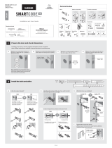
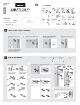
Parts in the box
Latch
Strike
Keys
Batteries
Spindle
Exterior
Assembly
Mounting
Plate
Fasteners
SmartKey
Tool
Interior
Assembly
If drilling a new door, use the supplied template and the complete
door drilling instructions available at www.weiserlock.com/doorprep.
backset
Measure to conirm that the hole in
the door is 54 mm (2 1/8 in).
*If you are installing this lever below
an existing lock or you plan to install a
lock above this lever, make sure that the
distance between holes is at least 165 mm
(6 1/2 in).
Measure to conirm that the backset is
either 60 or 70 mm (2 3/8 or 2 3/4 in).
60 or 70 mm
2 3/8 or 2 3/4 in
See
note
below*
35 – 44 mm
1 3/8 – 1 3/4 in
Measure to conirm that the hole in
the door edge is 25 mm (1 in).
Measure to conirm that the door is
between 35 and 44 mm (1 3/8 and
1 3/4 in) thick.
A
A C
B
D
E
B C D
Is the semi-circular hole of the latch centred in
the door hole?
Is the door edge chiselled?
Install strike on the door frame.
Hold the latch in front of the door hole, with the latch
face lush against the door edge.
Adjust the latch face (if needed).
lush
25 mm
1 in
YES NO
No adjustment is required.
Proceed to next step.
Move the pin to
extend the latch.
door frame
ENGLISH
Required tools
Hammer Wood block
Additional Tools (depending on application)
54 mm
2 1/8 in
For doors without chiselled edge
For square corners
Proceed to step 2D.
1. Remove square corner faceplate.
1. Remove plates.
Ensure A2
snaps into
place.
For round corners
2. Install round corner faceplate.
2. Install drive-in collar.
YES NO
slant of latch
bolt faces
door frame
slant of latch
bolt faces
door frame
wood block
J
A A2 A3
C
M
K
L
F
G
F2E H
Y2
Y1
A
A
A
A2 N (2x)
A3
or
or
chiselled not
chiselled
1Prepare the door and check dimensions
2Install the latch and strike

Install interior assembly onto mounting plate.Remove battery cover and battery pack from interior assembly.
A B
a
c
ba
bcd
Ensure correct polarity.
For best results, use
new, non-rechargeable
alkaline batteries only.
2 / 4
Install exterior keypad.
keep parallel to
edge of door
tighten
screws
evenly
Remove battery cover. Connect cable.
Install
battery
pack.
Push interior assembly onto
mounting plate.
Secure with
screws.
Ensure tight cable connection.
Push excess
cable back into
the door as you
install L.
Turnbutton
may need to
be turned to
install L.
Install 4 AA batteries into battery pack.
Remove
battery
pack.
rounded edge
faces latch
latch
Secure interior lever.
Route cable through mounting plate.
Install exterior lever.
Secure mounting plate with
supplied screws.
Secure exterior lever.
Install spindle.
Install interior lever.
The small bolt of the latch should not enter the strike
hole. If it enters the strike hole, reposition strike.
A
A
B
B
C
C
D
D
cable goes
over latch
Do not install
battery pack
into interior
assembly yet.
Lever handle
faces away
from the latch.
Tighten pre-
installed set
screw.
If latch is loose in the strike, adjust the strike tab so it
grips the latch bolt better when the door is closed.
tab
Tighten pre-
installed set
screw.
Lever handle
faces away
from the latch.
Close door, test latch operation and make adjustments as needed:
small bolt in
strike hole
small bolt NOT
in strike hole
F
M
J
K
K
K
Y1 or Y2 Y1 or Y2
Z Z
L
G
F2
T (2x)
U (2x)
actual
size
T
actual
size
U
3Install the exterior keypad, mounting plate, and spindle
4
5
6
Install interior assembly
Install levers
Test latch operation

1x 3x 2x
green red
3 / 4
Re-key the lock (if needed). Install the battery cover.
Conirm that the code(s) added in previous step can unlock the door.
A B
One green lash with one beep* Three red lashes with three beeps* Two beeps*
or or
IMPORTANT:
Remove battery
pack before
re-keying.
Make sure the door is open. Press
the Program button the number of
times that corresponds to the user
code position being programmed.
Locking the Door Unlocking the Door
Enter user code. A total of 30 user
codes may be programmed.
Press Lock button once.
A B C
What lights and sounds does the lock produce?
D
Each user code must
be a unique code
between 4 and 8 digits,
depending on your
smart home system.
Example: If
programming
the third code,
press the button
three times.
Programming was successful. Programming was unsuccessful.
Make sure the user code is not a duplicate and that it is
between 4 and 8 digits during your next attempt.
Programming time out.
Make sure not to pause for more than 5
seconds during programming.
Press Lock button once. Enter user code.
It is recommended that you add and
delete all user codes through your smart
home control system. If your system
does not allow this, codes may be added
directly to the lock as shown here.
Programming Timeout
If no button is pressed for 5 seconds, the
system will time out and you will need to
restart the procedure.
*Beeping sound will only be heard if switch #3 (on the lock interior) is in the on positon. See “Switches and Status LED Colours” on page 4.
Mastercode
For enhanced security, a mastercode may be used when adding and deleting user codes. For more information about the mastercode, download the Programming
and Troubleshooting Guide on the SmartCode 5 Lever page at www.weiserlock.com.
KK
M
H
V (2x)
Tip: You can press the
Lock button before
entering your user
code to light up the
keypad at night.
actual
size
V
a a
b b
c
Re-key the lock to work with your
existing key. See the supplied
SmartKey Re-key Instructions
for more information. Reinstall
battery
pack.
8
9
10
Add user codes (30 max)
Re-key the lock (if needed) and install the battery cover
Test the lock (review normal operation)
7Add the lock to your smart home system
button “A”
Please allow time for the controller to add the lock.
Initiate the process to add
the lock to your system at
your smart home controller.
Refer to your smart home
system instructions for
more information.
When prompted by your smart home system to add the
lock, press button “A” on the lock interior one time. The
red LED will illuminate when the lock enters Add Mode.
If successful, re-name the lock in your system
(if applicable).
If unsuccessful, follow your system's instructions to
remove the lock from the controller and any other
network, then press button “A” on the lock one time.
Perform steps 7A7C again.
If still unsuccessful, consult the Programming and
Troubleshooting Guide on the SmartCode 5 Lever
page at www.weiserlock.com.
A B C
D

ZWave System Notes
This product is a security enabled Z-wave Plus product and must be used with a Security
Enabled ZWave controller to be fully utilized. ZWave is a “Wireless mesh network,” and
results may vary based on building construction and communication path.
To assure interoperability, each ZWave product must pass a stringent conformance test to
assure that it meets the ZWave standard for complete compliance with all other devices and
controls. The ZWave identity mark assures consumers, integrators, dealers and manufacturers
that their products will reliably perform with any other ZWave device. And, regardless of the
vendor, always powered nodes may act as a repeater for Kwikset/Weiser/Baldwin products.
ZWave Coniguration and Association Parameters are available on
the SmartCode 5 Lever page at www.kwikset.com.
Removing the lock from the network
Follow your smart home system’s instructions
to remove the lock from the network. When
prompted by the system, press button A” on the
lock interior once.
© 2016 Spectrum Brands, Inc.
1. Read all instructions in their entirety.
2. Familiarize yourself with all warning and caution statements.
3. Remind all family members of safety precautions.
4. Protect your user codes and mastercode.
5. Dispose of used batteries according to local laws and regulations.
CAUTION: Prevent unauthorized entry. Since anyone with access to the back panel
can change the user codes, you must restrict access to the back panel and routinely
check the user codes to ensure they have not been altered without your knowledge.
The use of a mastercode can help protect your system’s settings.
WARNING: This Manufacturer advises that no lock can provide complete security
by itself. This lock may be defeated by forcible or technical means, or evaded by
entry elsewhere on the property. No lock can substitute for caution, awareness of
your environment, and common sense. Builder’s hardware is available in multiple
performance grades to suit the application. In order to enhance security and reduce
risk, you should consult a qualiied locksmith or other security professional.
Important Safeguards
Alert Reason Solution
Keypad lashes red 1 time
with 1 beep*
Door jammed while
attempting to lock.
Manually re-lock door. If needed,
reposition strike.
Keypad lashes red 3 times
with 3 beeps*
Unsuccessful programming. Attempt programming procedure
again.
One incorrect code entered. Re-enter code.
No user code programmed. Program at least one user code.
Keypad lashes red 10
times with 10 beeps* Low battery. Replace batteries.
Lock beeps 2 times.
Programming timeout.
Attempt programming procedure
again, making sure not to pause for
more than 5 seconds.
Keypad lashes red 3 times.
Keypad lashes red 6 times
with 6 beeps*.
Keypad lashes red 15 times
with 15 beeps*
Three incorrect codes entered
within one minute.
Re-enter code after 60-second keypad
lockout.
*Beeping sound will only be heard if switch #3 is on.
Network Information
4 / 4
SmartCode at a Glance
Deleting a User Code
In order to delete a user code, you must override the code by adding a dierent user code in the same
position. For example, if you want to delete the third code, add a dierent user code in position three.
Test the old user code to make sure it can no longer unlock the door.
If you cannot remember the user code position, you may wish to perform a factory reset to delete all
codes associated with the lock.
Reference Guide
Exterior
Back
panel
Program
button
Status
LED
Switches
Turnpiece
Interior (cover removed)
Switches and Status LED Colours
Troubleshooting
Switch Function
1Door lock status LED blinks every 6
seconds
2
Lock automatically re-locks door 30
seconds after unlocking. Disabled if no
codes are programmed.
3 Audio
4 Not used.
Colour Lock Status
Green Unlocked
Amber Locked
Red Low battery
1 2 3 4
On
Switches
Status
LED
O
System Alerts
Factory ResetBattery Replacement
A factory reset will delete all codes associated with the lock,
and it will remove it from your smart home system.
If another lock is installed above the lever, remove the interior
assembly when battery replacement is required.
Status
LED
1 Remove
battery pack.
2 Press and HOLD the Program
button while reinserting
the battery pack.
Keep holding the button for 30
seconds until the lock beeps
and the status LED lashes red.
Keypad
Lock
button
Keyway
SmartKey
tool hole
Button “A” Button “B”
3 Press the Program button
once more. When the LED
lashes green and you
hear one beep, the lock
has been reset.
4 Pair the lock with your smart home
system, and add user codes to your lock.
A complete Programming and Troubleshooting Guide is available on
the SmartCode 5 Lever page at www.weiserlock.com.
Lock
above
lever
Mounting
plate
Interior
assembly
Battery
pack

© 2017 Spectrum Brands, Inc.
1. Association Groups
The lock supports 2 association groups. Per Z-Wave Plus requirements, group 1 is
assigned to the Lifeline group and can only support 1 node.
The Lifeline group supports the following unsolicited messages:
Command Class Command
Command Class Battery Battery Report
Command Class Door Lock Door Lock Operation Report
Command Class Notification Notification Report
Command Class Device Reset Locally Device Reset Locally Notification
Association group 2 is identified as the “Doorlock notify report” group. It allows at
most 5 other nodes to be associated with the lock and will provide all Notification
Reports, via the Command Class Notification, generated by the lock.
2. Configuration Parameters
The Z-Wave door lock module supports the use of the configuration command class to
provide advanced configuration of the door lock over the Z-Wave network. This section
describes the configuration parameters supported by the door lock.
2.1 Configuration Parameters 1 through 30
Parameter Name: User Code Type
Data Length: 1 byte
Default Value: 1 (Owner)
Possible Values: 0x01 (owner), 0x03 (Guest), 0x04 (Worker)
Description:
Configuration parameters 1 through 30 are a one byte field used to set the type of user for
their corresponding user code. The following table shows the valid values for user code
types:

© 2017 Spectrum Brands, Inc.
Parameter Value Description
0x00 Reserved
0x01 Owner (Default)
0x02 Reserved
0x03 Guest (required for Year/Day schedules)
0x04 Worker (required for week day schedules)
0x05 – 0xFE Reserved
0xFF No User Code assigned
The door lock will only retain valid user code types (0x01, 0x03, and 0x04). All other
values will be ignored. If a user code does not exist for the corresponding configuration
parameter, the lock will report a value of 0xFF. Any attempts to change the user code for
a non-existent user will be ignored.
A user code can only be set to one user code type at a time and, as indicated in the table
above, user code types are associated with Schedule Entry Lock CC schedule types. This
association between user code type and entry schedule type correlates to the Schedule
Entry CC specification in that only one schedule type (week day or year day) may be
associated with a user code at any time. Note: This does not prohibit a user code from
having multiple schedules of the same type (Year Day or Week Day).
By default all user codes are assigned type “Owner” when created. The type “Owner”
designation indicates that that user code is active at all times. When an entry schedule is
created for a user code, the associated user code type will automatically change
depending on the type of schedule created. Example: If a weekday schedule is created for
a user code the associated user code type will change to “Worker”. If a year day schedule
is created for a user code the associated user code type will change to “Guest”.
If a user code is of type “Worker” or “Guest” it must have an enabled entry schedule to
have access to the lock. If a user code of type “Worker” or “Guest” does not have an
enabled schedule or if there are no entry schedules defined the associated user code will
not be given access by the lock.
To provide the user code access to the lock the system must perform one of three actions:
• Re-enable the entry schedule for the user code that was previously disabled
• Create a new entry schedule for the user code
• Change the user code type to “Owner”

© 2017 Spectrum Brands, Inc.
WARNING: If a user code is of type “Worker” or “Guest” and the system changes the
user code type to “Owner” the associated user code will be given access to the lock 24/7
regardless of any entry schedules defined for the user in the lock.
2.2 Configuration Parameter 31
Parameter Name: Dipswitch Settings
Data Length: 1 byte
Default Value: 5 (Buzzer enabled and Lock Status LED enabled)
Possible Values: 0 All features disabled
1 Lock status LED enabled
2 Autolock enabled
4 Internal buzzer enabled
3 Autolock and lock status LED enabled
5 Internal buzzer and lock status LED enabled
7 All features enabled
Description:
Configuration parameter is a one byte read only bit mask that returns the state of the user
accessible dipswitches on the rear panel of the door lock.
The following table shows the definition for the bits being used in the returned value:
Bit Description
0 (0x01) Lock status LED (1:enabled)
1 (0x02) Autolock setting (1:enabled)
2 (0x04) Buzzer (1:enabled)
3 (0x08) reserved
2.3 Configuration Parameters 33 and 34
Parameter Name: SKU (length = 8 bytes)
Data Length: 4 bytes (each parameter)
Default Values for 33 and 34: 0x20, 0x20, 0x20, 0x20 (all spaces)
Possible Values: 32 to 126 (All printable characters will be accepted)
Description:
The configuration parameters 33 and 34 are used to set and get the SKU part numbers.
The SKU is made up of 8 bytes. Each parameter consists of four bytes of data.
Parameter 33 contains the first four most significant bytes of the SKU, while parameter
34 contains the four least significant bytes of the SKU.

© 2017 Spectrum Brands, Inc.
When setting the SKU, it must be done in two set commands, one for each parameter.
The order of programming the SKU does not matter.
Setting parameter 33 will program the first four bytes of the SKU. Setting parameter 34
will program the last 4 bytes of the SKU. Most printable values are accepted for the set
command.
When getting the SKU, it must be done in two get commands, one for each parameter.
The order of getting the SKU does not matter.
Getting parameter 33 will retrieve the first four bytes of the SKU. Getting parameter 34
will retrieve the last 4 bytes of the SKU.
2.4 Configuration Parameter 40
Parameter Name: Reset Lock to Factory Default
Data Length: 1 byte
Default Value: 0
Possible Values: 1 – have lock perform factory reset
Description:
The configuration parameter 40 is a one byte field, used to set the lock to its default
setting, known as a factory reset command.
Reading this parameter will always return a value of 0.
Writing a value of 1 to this parameter will cause both the lock and Z-Wave card to reset
back to their default settings and will remove itself from the network. All network
information, including associations will be cleared.
3. Inclusion Procedures
1. Power the lock by placing the battery pack into the lock
2. On the controller, select the option to add a device.
3. On the lock, press button ‘A’. The red LED will illuminate until the add request has been processed.

© 2017 Spectrum Brands, Inc.
4. Exclusion Procedures
1. Power the lock by placing the battery pack into the lock
2. On the controller, select the option to remove a device
3. On the lock, press button ‘A’. The red LED will illuminate until the removal request has been
processed.
5. Reset Procedures
A factory reset will delete all codes associated with the lock and will remove it from your smart home
system. It will not remove any anti-theft settings.
Please use the local reset procedure only when the primary controller is missing or inoperable.
5.1 Local
1. Remove battery pack and press the program button a few times to discharge.
2. Press and hold the program button.
3. Replace the battery pack.
4. Continue holding the program button for 30 seconds until the lock beeps and the state LED flashes red.
5. Press the program button again. The status LED will flash green.
6. When the cycle of red and green flashes ends, the reset has completed.
7. Wait for the lock to reboot.
5.2 Remotely
1. From a controller, write a 0x01 to configuration parameter 40.
2. When the cycle of red and green flashes ends, the reset has completed.
3. Wait for the lock to reboot.
/