Page is loading ...

- 4 -
Fig. 6 – Dimensions (mm)
For help or more information about this product or other fine access control products from
SECO-LARM, please visit our website at www.enforcer.com.tw.
Troubleshooting:
1. If the door does not release when the electric strike is activated — Open the door, and leave
it open. Activate the electric strike to ensure if it is operating properly:
a. If the strike operates properly with the door open, the problem is probably a poor door
latch, or the position of the electric strike needs to be adjusted by moving it or adding
washers or shims. Test again.
b. If the strike does not operate properly with the door open, dismount the strike and check
that the two wires are connected properly. Also ensure the wires are connected to
12 VDC power supply. Test again.
c. Use a multimeter to test that the strike is receiving the proper voltage and amperage. If
not, it may be necessary to use heavier gauge wires, or increase the output of the power
supply.
d. If all the above tests do not locate the problem, then make sure the activation device
(keypad, push-button switch, or whatever) is activating properly.
2. If the door does not lock properly when closed — This is probably a problem with the
installation or with a bad door latch. In this case, it may be necessary to adjust the position of
the strike, or possibly replace the latch.
3. For any other problems, replace the unit, and test again. The problem unit can also be
substituted for a working unit in another door frame to see if it works there.
Warranty:
ENFORCER Electric Door Strikes are warranted against defects in material and workmanship
while used in normal service for a period of one (1) year from the date of sale to the original
customer. Our obligation is limited to the repair or replacement of any defective part if the unit is
returned, transportation pre-paid, to SECO-LARM.
Notice:
The information and specifications printed in this manual are current at the time of publication.
However, the SECO-LARM policy is one of continual development and improvement. For this
reason, SECO-LARM reserves the right to change specifications without notice. SECO-LARM is
also not responsible for misprints or typographical errors.
Copyright © 2011 SECO-LARM U.S.A., Inc. All rights reserved. This material may not be
reproduced or copied, in whole or in part, without the written permission of SECO-LARM.
SECO-LARM
®
U.S.A., Inc.
1
6842 Millikan Avenue, Irvine, CA 92606
Website: www.seco-larm.com
Tel: 800-662-0800 / 949-261-2999 Fax: 949-261-7326 E-mail: sales@seco-larm.com
MiSD991xE1Q_1107.docx
PITBW1
- 1 -
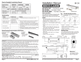
Installation Manual
ENFORCER
®
Electric Door Strikes
SD-991A-E1Q Fail-Secure
(Door locked with power disconnected)
SD-991B-E1Q Fail-Safe
(Door unlock with power disconnected)
Features:
•
Convert mortise lock sets to electronic
access control locking systems.
• Use on virtually any mortise door locking
system.
• Use with an optional digital keypad such as
SECO-LARM’s SK-1011-SQ or SK-1131-SQ
for keyless high security.
• Reversible for right-hand or left-hand doors.
• Shallow design for use with most doors.
•
Stainless steel lip (keeper) for strength and
long life.
•
Non-polarized connection. Wires can be
reversed.
• Fail-Secure (SD-991A-E1Q) units are
perfect for entrance door installations.
• Fail-Safe (SD-991B-E1Q) units are perfect
for emergency door and escape door
installations.
• Suitable for office-type applications.
Specifications:
Type Circuit type Input voltage Current Draw
SD-991A-E1Q Fail-Secure N.O 12 VDC 400 mA
SD-991B-E1Q Fail-Safe N.C 12 VDC 200 mA
Installation
1. Prepare door jamb as per drawing.

- 2 -
2. Application Requirements:
a. Suitable for door thickness 30~40 mm.
b. Allowable latch cavity not to exceed 3 mm as shown below.
3. Measure:
Note: SD-991A and SD-991B are mounted the same way.
A. Latch line (see fig. 1):
1). Measure the distance between the face of the door jamb and the face of the door latch.
If the door latch has a deadlatch pin, ignore the deadlatch pin when measuring. This is
the vertical latch distance.
2). Measure the vertical latch distance on the door jamb from the face of the door jamb. At
that point, draw a vertical line. This is the latch line.
B. Center line (see fig. 2):
1). Measure the distance from the floor to the center of the door latch. Ignore the location of
the deadlatch pin when measuring.
2). Measure that distance from the floor along the inside of the door jamb. At that point,
draw a horizontal line. This is the center line.
4. Mount The Template:
Align and tape the template on the door jamb to the latch line and the center line, and tape it
(see fig. 3)
5. Cut:
Cut into the door jamb as shown on the template (see fig. 4). Cut into the door jamb to a depth
of 17 mm. Dispose or recycle the metal which was cut out.
Note: If wood door, use a chisel to knock out a 3 mm. (1/8 inch) deep space as shown on the
template. (See fig. 4)
6. Double-Check The Cut:
Place the unit in the hole, and make sure it fits properly. Make any necessary adjustments.
7. Connect Wires and Insulate:
Connect the two wires to the access control or egress device, such as a digital keypad,
push-button switch, push bar, or other device. Polarity is not important. Insulate the wire
connections carefully.
8. Mounting:
Push all the wires into the door frame. If needed, cut away the dust catcher inside the frame,
or carefully chip away part of the drywall, being careful to not harm the wall. Adjust as needed
to ensure the door closes smoothly every time someone passes through the protected
opening. See fig. 5.
Lockset Latch
Too Big
Latch
3mm
Lockset
- 3 -
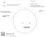
Fig. 4
–
Cutting the hole
using the template
Note: If wood door,
use a chisel to
knock out a 3mm
(1/8”) deep space as
shown on the
template.
Door jamb
17mm
Door
Door latch
Deadlatch pin
Fig.
1
–
Measuring
the latch
line
Door jamb
Vertical
latch
distance
Latch line
Door knob
Fig.
2
–
Measuring
the center
line
Center line
Door latch
Door jamb
Template
Door jamb
Center line
Latch line
Fig.
3
–
Aligning the
template
Dimensions needed
to install strike.
Unit: mm
Fig.
5
–
Mounting
Connect with wires and insulate before installing the strike.
S/S or Aluminum door frame
Wooden
door frame
/