Page is loading ...

MP8D
EIGHT CHANNELS MICROPHONE/INSTRUMENT
PREAMPLIFIER WITH DIGITAL OUTPUT
OWNER'S MANUAL
www.altoproaudio.com
Version 1.2 SEPTEMBER 2007
LTO
R
English

CAUTION
RISK OF ELECTRIC SHOCK
DO NOT OPEN
IMPORTANT SAFETY INSTRUCTION
TO REDUCE THE RISK OF ELECTRIC SHOCK
PLEASE DO NOT REMOVE THE COVER OR
THE BACK PANEL OF THIS EQUIPMENT.
THERE ARE NO PARTS NEEDED BY USER
INSIDE THE EQUIPMENT. FOR SERVICE,
PLEASE CONTACT QUALIFIED SERVICE
CENTERS.
WARNING
To reduce the risk of electric shock
and fire, do not expose this equipment
to moisture or rain.
1.
2.
3.
4.
5.
6.
7.
8.
9.
10.
Dispose of this product should
notbeplacedinmunicipalwaste
and should be separate collection.
11.
12.
MovethisEquipmentonlywithacart,
stand, tripod, or bracket,
specified by the
manufacturer, or
sold with the
Equipment. When
a cart is used, use
caution when
moving the cart /
equipment
combination to
avoid possible
injury from tip-over.
Permanent hearing loss may be caused by
exposure to \ extremely high noise levels.
The US. Government's Occupational Safety
and Health Administration (OSHA) has
specified the permissible exposure to noise
level.
These are shown in the following chart:
HOURS X DAY SPL EXAMPLE
According to OSHA, an exposure to high SPL in
excess of these limits may result in the loss of
heat. To avoid the potential damage of heat, it is
recommended that Personnel exposed to
equipment capable of generating high SPL use
hearing protection while such equipment is
under operation.
8
6
4
3
2
1,5
1
0,5
0,25 or less
90
92
95
97
100
102
105
110
115
Small gig
train
Subway train
High level desktop monitors
Classic music concert
Rock concert
This symbol, wherever used, alerts you to the
presence of un-insulated and dangerous voltages
within the product enclosure. These are voltages that
may be sufficient to constitute the risk of electric
shock or death.
This symbol, wherever used, alerts you to
important operating and maintenance instructions.
Please read.
Protective Ground Terminal
AC mains (Alternating Current)
Hazardous Live Terminal
ON: Denotes the product is turned on.
OFF: Denotes the product is turned off.
The apparatus shall be connected to a mains
socket outlet with a protective earthing
connection.
The mains plug or an appliance coupler is used
as the disconnect device, the disconnect device
shall remain readily operable.
CAUTION
Describes precautions that should be observed to
prevent damage to the product.
Read this Manual carefully before operation.
Keep this Manual in a safe place.
Be aware of all warnings reported
with this symbol.
Keep this Equipment away from water and
moisture.
Clean it only with dry cloth. Do not use
solvent or other chemicals.
Do not damp or cover any cooling opening.
Install the equipment only in accordance with
the Manufacturer's instructions.
Power Cords are designed for your safety. Do
not remove Ground connections! If the plug
does not fit your AC outlet, seek advice from
a qualified electrician. Protect the power
cord and plug from any physical stress to
avoid risk of electric shock. Do not place
heavy objects on the power cord. This could
cause electric shock or fire.
Unplug this equipment when unused for long
periods of time or during a storm.
Refer all service to qualified service personnel
only. Do not perform any servicing other than
those instructions contained within the
User's Manual.
To prevent fire and damage to the product,
use only the recommended fuse type as
indicated in this manual. Do not short-circuit
the fuse holder. Before replacing the fuse,
make sure that the product is OFF and
disconnected from the AC outlet.

IN THIS MANUAL:
1. INTRODUCTION....................................................................................1
2. FEATURES...........................................................................................1
3. QUICK START.......................................................................................2
4. CONTROL ELEMENTS..........................................................................4
5. INSTALLATION & CONNECTION............................................................7
6. APPENDIX ........................................................................................10
6. BLOCK DIAGRAM...............................................................................11
7. TECHNICAL SPECIFICATIONS
8. WARRANTY........................................................................................13
...............................................................12
1. INTRODUCTION
Thank you for your purchasing the MP8D microphone/instruments preamplifier with
digital output. It is just one of the many LTO products that a talented, multinational
Team of Audio Engineers and Musicians have developed with their great passion for
music. The MP8D ESOTAR has been built with no economy thinking at the challenges
of the digital era. It is made in road-worthy and durable package for live and recording
studio applications. The MP8D ESOTAR includes the same high-end microphone pre-
amplifiers used in the renewed LTO Typhoon large format mixing console. Their
performance rivals with the world's best preamplifiers that cost three or four time
more. The MP8D ESOTAR is equipped with both analogue and digital outputs, and
therefore, it can be used great flexibility with analogue Live Consoles, Digital Audio
Workshop and Hard Disk Recording. Channel 1&2includeahigh-impedance instrument
input so that you don't need an external D/I box to connect an electric guitar or bass
to these inputs. Then, each of the eight channels has a phantom power switch, a low-
cut switch and a GAIN control. The available gain is 60 dB, so a Line switch is not
needed. The sample rate selector allows you to select 44.1k, 48k, 44.1k 2, 48k 2,
44.1k 4, 48k 4 or sample rate, or to use an external clock. MP8D ESOTAR features
an outstanding 128 dB of S/N ratio; a frequency response extended to 200 kHz and
a THD of 0,007%. The characteristics make MP8D ESOTAR to be one of the most
transparent and advanced Microphone/Instrument preamplifiers available today.
Enjoy your MP8D ESOTAR and make sure to read this Manual carefully before operation!
2. FEATURES
Ultra-Wide Dynamic Range
Low-Noise Operating Levels
+48 V Phantom Power on every Channel
Instrument Input on Channel1&2
Eight 24-bit ADC Converters
ADAT Lightpipe Output TM
AES/EBU Outputs 24 bit/192 kHz
1/4" TRS Balanced Analogue Outputs
1
BNC Word Clock I/O for Sync

2
This is the fastest way to get something out from your MP8D, if you have a keyboard and
a microphone.
a. Keep the Power switch in OFF position.
b. Turn down all the GAIN controls.
c. All the switches must be in OUT position.
d. Plug-in a microphone on Channel 1 MIC input.
e. Connect the output of Channel 1 (use the INSERT socket) to your mixer.
g. Connect the AES/EBU output of your MP8D to a digital input of your HDR or DAW.
h. Connect the ADAT pipeline of your MP8D to your ADAT Recorder.
Hereyouare.ItisyourMP8D.
f. Sing or speak into the microphone with normal volume and adjust the channel LEVEL
control of half.
3. QUICK START
i. If you are using a dynamic microphone, keep the +48V (phantom power) switch in OFF
position. If you are using a condenser microphone, press it in ON position.
j. Sing something into the microphone with normal volume and adjust the GAIN, so that
the -20 and 0 LEDs light continuously. CLIP LED should flash occasionally or not at all.
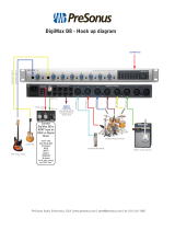
HOOK
UP
MP8DWITHADAW
CH.1
MIC. IN
OUT
WORD CLOCK
DIGITAL OUT
ADAT
S/PDIF-AES/EBU
AC INPUT
210-240V 50Hz
Rated Power
Consumption 35W
FUSE:
250V: T315mAL
REPLACE FUSE
WITH CORRECT
TYPE ONLY
Apparaten
skall anslutas
till
jordat uttag
nar den
ansluts
till ett natverk
CH.2
MIC. IN
CH.3
MIC. IN
CH.4
MIC. IN
CH.5
MIC. IN
CH.6
MIC. IN
CH.7
MIC. IN
CH.8
IN
MIC. IN
INSERTINSERTINSERTINSERTINSERTINSERTINSERT
INSERT
Use only with a 250V fuse
PUSH
21
3
J.T.
PUSH
21
3
J.T.
21
3
J.T.
21
3
J.T.
21
3
J.T.
21
3
J.T.
GUITAR
BASS
DAW = Digital Work Station
Signal converter

CH.1
MIC. IN
OUT
WORD CLOCK
DIGITAL OUT
ADAT
S/PDIF-AES/EBU
AC INPUT
210-240V 50Hz
Rated Power
Consumption 35W
FUSE:
250V: T315mAL
REPLACE FUSE
WITH CORRECT
TYPE ONLY
Apparaten
skall anslutas
till
jordat uttag
nar den
ansluts
till ett natverk
CH.2
MIC. IN
CH.3
MIC. IN
CH.4
MIC. IN
CH.5
MIC. IN
CH.6
MIC. IN
CH.7
MIC. IN
CH.8
IN
MIC. IN
INSERTINSERTINSERTINSERTINSERTINSERTINSERT
INSERT
Use only with a 250V fuse
PUSH
21
3
J.T.
PUSH
21
3
J.T.
21
3
J.T.
21
3
J.T.
21
3
J.T.
21
3
J.T.
GUITAR
BASS
HOOK
UP
MP8D WITH ADAT RECORDING DEVICE
HOOK
UP
MP8D IN LIVE APPLICATION
3
CH.1
MIC. IN
OUT
WORD CLOCK
DIGITAL OUT
ADAT
S/PDIF-AES/EBU
AC INPUT
210-240V 50Hz
Rated Power
Consumption 35W
FUSE:
250V: T315mAL
REPLACE FUSE
WITH CORRECT
TYPE ONLY
Apparaten
skall anslutas
till
jordat uttag
nar den
ansluts
till ett natverk
CH.2
MIC. IN
CH.3
MIC. IN
CH.4
MIC. IN
CH.5
MIC. IN
CH.6
MIC. IN
CH.7
MIC. IN
CH.8
IN
MIC. IN
INSERTINSERTINSERTINSERTINSERTINSERTINSERT
INSERT
Use only with a 250V fuse
PUSH
21
3
J.T.
PUSH
21
3
J.T.
21
3
J.T.
21
3
J.T.
21
3
J.T.
21
3
J.T.
GUITAR
BASS
D1
500W 2
(dB)
12
16
18
20
22
24
26
28
30
6
CH1
(dB)
12
16
18
20
22
24
26
28
30
6
CH2
SIGCLIP PROT SIGCLIP PROT
20 31.5 50 100 200 500 1.25K 2.5K 6.3K 12.5K25 40 80 160 400 1K 2K 5K 10K63 125 315 800250 630 1.6K 4K3.15K 8K 16K 20K
20 31.5 50 100 200 500 1.25K 2.5K 6.3K 12.5K25 40 80 160 400 1K 2K 5K 10K63 125 315 800250 630 1.6K 4K3.15K 8K 16K 20K
ChannelOne
ChannelTwo
Dual31 Band Graphic Equalizer
INPUT
LEVEL
0
0dB
+12
-12
+12
-12
+6
-6
INPUT
LEVEL
0
0dB
+12
-12
+12
-12
-6
+6
INPUT OUTPUT
ON40Hz 16KHz
126
SIG
CLIP
SIG
CLIP
EQRANGE
HI
PASS
LOW
PASS
ON40Hz 16KHz
12
6
EQRANGE
HI
PASS
LOW
PASS
INPUT OUTPUT
SIG
CLIP
SIG
CLIP
EQU231
MK V2
R
LTO
EQUALIZER
AMPLIFIER
Digital Mixer

20 0 CLIP
INSTRUMENT
1
2
34
5
678
INSTRUMENT
44.1K
248K 4
EXT. CLOCK
8 CHANNEL
MIC PRE-AMPLIFIER
48V SAMPLE RATE48V48V48V48V48V48V48V
POWER
MP8D
GAIN
60dB
0
GAIN
60dB
0
GAIN
60dB
0
GAIN
60dB
0
GAIN
60dB
0
GAIN
60dB
0
GAIN
60dB
0
GAIN
60dB
0
GAIN
CLIP CLIP CLIP CLIP CLIP CLIP CLIP000000020 20 20 20 20 20 20
60dB
0
ESOTAR
R
4
SPOTLIGHT
4. CONTROL ELEMENTS
1 1/4" INSTRUMENT Input (only channel 1 and channel 2)
These two high-impedance 1/4" instrument inputs have been designed to
connect instruments such as electric guitar or bass directly into the unit
without passing through an external D/I Box.
NOTE: please do not use the built in pre-amp of active instruments (when
available) in order to avoid distortion caused by over-driving the input signal.
FRONT PANEL
2 GAIN control
This control adjusts the input sensitivity of the relative channel. Through
this control audio signals from the outside world are adjusted for an optimal
internal operating level. When a signal is applied to the XLR inputs on the
rear panel you have 0 dB of gain with the GAIN control turned down completely.
You get 60 dB of gain with this control turned all the way up.
3 +48V (phantom power) switch
Professional condenser microphone requires the phantom power. This is a
low-current DC voltage delivered through pin2&3oftheXLRmicrophone
connector. Push the +48V switch to activate this function, and it will light
up to confirm that the function is active. Dynamic microphone does not need
the phantom power but this will not give them any damage. However, old
ribbon microphone can be seriously damaged by phantom power. We advise
you always to check the manual of your microphone and see if it requires
phantom power or not.
4 HIGH-PASS FILTER
This filter provides an 80 Hz high pass filter for each channel. When you press
it will light-up confirming that the function is active. This filter is useful for
eliminating extraneous low-end information from the input signal. Frequencies
at 80Hz and below are cut from the incoming signal. This filter is useful in
eliminating low frequency noise such as air-conditioning rumble or for reducing
the sound of footsteps or other types of vibration from being transmitted
through the microphone stand into the microphone.
21 4
53
98
7
6
1

CH.1
MIC. IN
OUT
WORD CLOCK
DIGITAL OUT
ADAT
S/PDIF-AES/EBU
AC INPUT
210-240V 50Hz
Rated Power
Consumption 35W
FUSE:
250V: T315mAL
REPLACE FUSE
WITH CORRECT
TYPE ONLY
Apparaten
skall anslutas
till
jordat uttag
nar den
ansluts
till ett natverk
CH.2
MIC. IN
CH.3
MIC. IN
CH.4
MIC. IN
CH.5
MIC. IN
CH.6
MIC. IN
CH.7
MIC. IN
CH.8
IN
MIC. IN
INSERTINSERTINSERTINSERTINSERTINSERTINSERT
INSERT
Use only with a 250V fuse
PUSH
21
3
J.T.
PUSH
21
3
J.T.
21
3
J.T.
21
3
J.T.
21
3
J.T.
21
3
J.T.
5
REAR PANEL
14
13
12
11
10
15
SPOTLIGHT
4. CONTROL ELEMENTS
5 SIGNAL LEVEL LEDS
These LEDs show you the signal level after the GAIN control. -20 and 0dB
LEDs should always light, and CLIP LED should not flash at all to avoid
distortion. If CLIP LED flashes, you must turn down the GAIN control or
reduce the signal at its source.
Your MP8D is provided with 6 different sample rates: 44.1k, 48k, 44.1k x 2,
48k x 2, 44.1k x 4, 48k x 4. You can use this switch to select the right sample
rate.
6 SAMPLE RATE Selector Switch
When the lighted switch is engaged, the sample rate will be determined by the
input signal from "WORK IN" on the rear panel.
8 EXT Clock Switch
NOTE: If you want to use the EXT CLOCK, you must press the EXT Clock
switch to activate EXT Clock function. The lighted external clock switch lights
up when the unit is working. Then these four sample rate LED indicators flash
circularly. The Sample rate selector switch is invalidated. If you want to use
internal sample rate, please press the external clock switch again to turn off
the EXT CLOCK function.
It switches your MP8D ON and OFF.
9 POWER switch
These four LEDs will show you the value of the sample rate you have chosen.
When one Led lights-up, it will indicate the sample rate value: 44.1K or 48K,
when two of the other LEDs combine, values are: 44.1k x 2, 48k x 2, 44.1k x 4,
48kx4.
7 Sample Rate LED Indicator

6
Standard IEC receptacle. Connect your MP8D an AC socket with the supplied
power cord. Before powering up your MP8D for the first time, make certain
the stated power requirement of the unit matches the voltage supplied by the
AC socket.
If the fuse blows, replaced with a fuse of the correct type only.
This Toslink connector provides a digital output in ADAT lightpipe format. You can
use the AES/EBU output and the ADAT output simultaneously. For example, you
can use the AES/EBU output to input the 8 channels of your MP8D into a digital
mixer and at the same time record the same channels into an ADAT recorder
through the ADAT pipeline.
These female XLR connectors can be used with any balanced microphone. The
MP8D microphone preamplifiers are the same used in Alto Large Format Mixer
TYPHOON and offer an amazing audio quality and headroom. They rival with the
best stand alone microphone preamplifiers available on the market.
Through these stereo1/4" TRS sockets you can send the analogue signal out
and also insert an external sound processor using a Y-type cable.
The female nine-pin (DB9) connector provides 24 bit digital output. This connector
is a professional interface for transmitting the digital audio signal, which comes
configured for AES/EBU output when used the balanced cable with XLR plug. (The
connection details please refer to chapter 5.3)
The Word clock output and input are accessed through these separate BNC
connectors. The internal sample rate can send out 44.1k, 48k, 44.1k 2, 48k 2,
44.1k 4, 48k 4 sampling rate. The Word Clock In scans the incoming sample
rate and automatically synchs to it. These two connectors can daisy-chain
multiple MP8D. The clock signal will be transmitted from "clock out" on one MP8D
into the next MP8D "clock in". In this way, more units can be used together.
10 AC Inlet
11 WORD CLOCK IN/OUT
12 AES/EBU Connector
13 DIGITAL OPTICAL OUTPUT
14 MIC IN
15 INSERT
SPOTLIGHT
4. CONTROL ELEMENTS

5.1 Mains Connection
Please ensure that the MP8D is set to the correct supply voltage before plugging
the power cord into the wall outlet, use the same fuse as marked on the fuse
holder at the AC power connection. The mains connection of the MP8D is made
by using the enclosed mains cord and a standard IEC receptacle. It meets all
of the international safety certification requirements.
5.2 Audio Connection
The MP8D presents with balanced XLR & 1/4" TRS and combo connectors. It
can be interfaced in several ways to support a variety of applications without
any signal loss. The MP8D can be used on a single instrument by connecting to
the mixing console's main inserts, or on an entire mix "in-line" between a mixing
console's outputs and a power amplifier. The defective wiring may degrade the
performance of MP8D, so please use good quality screened audio cables only.
Please follow the guide below to interface MP8D without experiencing any noise
or signal loss.
7
Ok, you have got to this point and you are now in the position to operate your
MP8D successfully. However, we advise you to read carefully the following section
to be the real master of your own mix. Not paying attention enough to the input
signal level, to the routing of the signal and the assignment of the signal will result
in unwanted distortion, a corrupted signal or no sound at all. So you should follow
this procedure for every single channel:
5. INSTALLATION AND CONNECTION
Strain Clamp
Sleeve
Tip
Ring
Sleeve=Ground/Screen
Ring=Right Signal
Tip=Left Signal
Use for Headphone
1/4" Stereo (TRS) Jack Plug
Strain Clamp
Sleeve
Tip
Sleeve=Ground/Screen
Tip=Signal
Use for Mono Line In, Mono 1/4" Jack Plugs
1/4" Mono (TS) Jack Plug

8
Strain Clamp
Sleeve
Tip
Ring
Sleeve=Ground/Screen
Ring=Return Signal
Tip=Send Signal
Use for Insert Points
1/4" Stereo (TRS) Jack Plug
2=Hot(+)
3=Cold(-)
1=Ground/Screen
(seen from soldering side)
Use for Balanced Mic Inputs
(For unbalanced use, connect pin 1 to 3)
3-pin XLR Male Plug
2=Hot(+)
3=Cold(-)
1=Ground/Screen
3-pin XLR Line Socket
(seen from soldering side)
1
2
3
1
2
3
Use for Main output
(For unbalanced use, leave pin3 unconnected)
Insert Leads
5. INSTALLATION AND CONNECTION
21
3
1
2
3
TIPRINGSLEEVE
Tip
Ring
Sleeve
1
2 (Send)
3
1
2 (Return)
3
TIP RING SLEEVE
Centre (Send)
Screen
Centre (Return)
Screen
Tip
Ring
Sleeve
SLEEVE TIP
SLEEVE RING TIP
TIPRINGSLEEVE
Tip
Ring
Sleeve
Tip (Send)
Sleeve
Sleeve
Tip (Return)

9
5. INSTALLATION AND CONNECTION
5.3 AES/EBU and S/PDIF connectors
CN-RCA2-1
DB9 RCA socket
(female)
Yellow (For the digital output of CH1/CH2)
White (For the digital output of CH3/CH4)
Red (For the digital output of CH5/CH6)
Black (For the digital output of CH7/CH8)
DB9
CN-RCA2-1
CN-RCA2-1
CN-RCA2-1
1
6
2
7
3
8
4
9
5
Yellow (For the digital output of CH1/CH2)
White (For the digital output of CH3/CH4)
Red (For the digital output of CH5/CH6)
Black (For the digital output of CH7/CH8)
DB9 XLR socket
(female)
CN-BAL-FEMALE-2
CN-BAL-FEMALE-2
CN-BAL-FEMALE-2
CN-BAL-FEMALE-2
1
6
2
7
3
8
4
9
5
DB9
2
3
1
2
3
1
2
3
1
2
3
1
S/PDIF CONNECTOR
AES/EBU CONNECTOR
Note: For these two kinds of connectors which mentioned above are at buyer's
option. You can buy them from your dealer.

10
Our products are shipped in AES/EBU mode, to change to consumer(S/PDIF)
mode, please follow the jumper settings as below. There are 5 jumpers in
total: 4 double jumpers and 1 single.
The picture 1 is the original setting (AES/EBU mode):
The picture 2 is the Consumer SPDIF mode)setting (
6. APPENDIX
Jumper
Picture 1
Jumper
Picture 2

11
7. BLOCK DIAGRAM

12
8. TECHNICAL SPECIFICATION
PHYSICAL
Dimension
Net Weight
W(483.0) D(288.0) H(44.2) mm
3.3 Kg
INPUT
Connectors
Impedance
Max input level
CMRR
Six balanced XLR, Two 1/4" TRS Instrument Inputs and Two
Combo on Ch1 and CH2
Balanced >50 kOhm, Unbalanced>25 kOhm
>+24 dBu balanced and unbalanced
Typically>60 dB at 1 kHz
OUTPUT
Connectors
Impedance
Max output level
Eight 1/4" TRS (INSERT)
ADAT Light-Pipe Dight Optical
AES/EBU
Unbalanced>60ohm
>+21dBu unbalanced
SYSTEM SPECIFICATIONS
Bandwidth
Frequency Response
Signa/Noise
THD
Crosstalk
Stereo Coupling
Digital
20 Hz to 20 kHz, +0/-0.5 dB
10 Hz to 200 kHz,+0/-3 dB
>128 dBu, weighted, 22 Hz to 22 kHz
<0.007%
<-100 dB, 22 Hz to 22 kHz
True RMS detection
Sampling Rates
44.1K,48K,44.1K x2,48K x2,44.1K x4,48K x4
Output
24-bit
FUNCTION SWITCHES
48 Volt Phantom Power
High pass filter
Sample
Ext.clock
Eight channel of the MP8D has 48V Phantom power available
>80 Hz
Six sample rates
On/Off
INDICATORS
INPUT LEVEL
Function switch
3 element LED display: -20 / 0 / CLIP dB.
LED indicator for each
POWER SUPPLY
Mains Voltages
Fuse
Power consumption
Mains Connection
~120 VAC, 60 Hz
~240 VAC, 50 Hz
~230 VAC, 50 Hz
~100-120 VAC,
~200-240 VAC, 50-60 Hz
USA/Canada
U.K./Australia
Europe
General Export Model
100-120 VAC : 400 mA (SLOW-BLOW)
200-240 VAC : 200 mA (SLOW-BLOW)
35 Watts
Standard IEC receptacle

9. WARRANTY
1. WARRANTY REGISTRATION CARD
To obtain Warranty Service, the buyer should first fill out and return the enclosed
Warranty Registration Card within 10 days of the Purchase Date.
All the information presented in this Warranty Registration Card gives the
manufacturer a better understanding of the sales status, so as to provide a
more effective and efficient after-sales warranty service. Please fill out all the
information carefully and genuinely, miswriting or absence of this card will void
your warranty service.
2. RETURN NOTICE
2.1 In case of return for any warranty service, please make sure that the
product is well packed in its original shipping carton, and it can protect your
unit from any other extra damage.
2.2 Please provide a copy of your sales receipt or other proof of purchase with
the returned machine, and give detail information about your return address
and contact telephone number.
2.3 A brief description of the defect will be appreciated.
2.4 Please prepay all the costs involved in the return shipping, handling and
insurance.
3. TERMS AND CONDITIONS
3.1 LTO warrants that this product will be free from any defects in materials
and/or workmanship for a period of 1 year from the purchase date if you
have completed the Warranty Registration Card in time.
3.2 The warranty service is only available to the original consumer, who purchased
this product directly from the retail dealer, and it can not be transferred.
3.3 During the warranty service, LTO may repair or replace this product at its
own option at no charge to you for parts or for labor in accordance with the
right side of this limited warranty.
3.4 This warranty does not apply to the damages to this product that occurred
as the following conditions:
Instead of operating in accordance with the user's manual thoroughly, any abuse
or misuse of this product.
Normal tear and wear.
The product has been altered or modified in any way.
Damage which may have been caused either directly or indirectly by another
product / force / etc.
Abnormal service or repairing by anyone other than the qualified personnel or
technician.
And in such cases, all the expenses will be charged to the buyer.
3.5 In no event shall LTO be liable for any incidental or consequential damages.
Some states do not allow the exclusion or limitation of incidental or
consequential damages, so the above exclusion or limitation may not apply to
you.
3.6 This warranty gives you the specific rights, and these rights are compatible
with the state laws, you may also have other statutory rights that may vary
from state to state.
13

NF02206-1.2
c
All rights reserved to ALTO. All features and content might be changed
without prior notice. Any photocopy, translation, or reproduction of part of this
manual without written permission is forbidden. Copyright 2007 Seikaku Group
SEIKAKU TECHNICAL GROUP LIMITED
NO. 1, Lane 17, Sec. 2, Han Shi West Road, Taichung 40151, Taiwan
http://www.altoproaudio.com Tel: 886-4-22313737
/