
2
Model BDF • Belt Drive Duct Fan
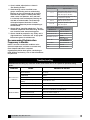
Receiving
Upon receiving the product check to make sure all
items are accounted for by referencing the bill of lading
to ensure all items were received. Inspect each crate
for shipping damage before accepting delivery. Notify
the carrier if any damage is noticed. The carrier will
make notication on the delivery receipt acknowledging
any damage to the product. All damage should be
noted on all the copies of the bill of lading which
is countersigned by the delivering carrier. A Carrier
Inspection Report should be lled out by the carrier
upon arrival and reported to the Trafc Department.
If damaged upon arrival, le a claim with carrier. Any
physical damage to the unit after acceptance is not the
responsibility of Greenheck Fan Corporation.
Unpacking
Verify that all required parts and the correct quantity
of each item have been received. If any items are
missing, report shortages to your local representative
to arrange for obtaining missing parts. Sometimes it
is not possible that all items for the unit be shipped
together due to availability of transportation and truck
space. Conrmation of shipment(s) must be limited to
only items on the bill of lading.
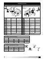
Handling
Move fan to desired location and determine position
of access panels and motor. Make sure inlet and
outlet have at least 2 times the wheel diameter
(duct diameter) before any obstructions like an elbow
or transition. Attach the fan to a suitable framework
as specified, (hanging or base vibration isolators are
recommended). See chart 1 on page 3 for physical
dimensions (figure 1) and chart 3 on page 3 for
dimensions of vibration isolators (figure 3).
The motor
’
s amperage and voltage ratings must be
checked for compatibility to supply voltage prior
to final electrical connection. Supply wiring may be
routed through knockouts which are provided on
the top and bottom of each fan housing. Provide
adequate wiring to permit the access doors to open
for servicing. Wiring should be secured inside the fan
to prevent interference with the drive components. All
wiring must conform to local and national codes.
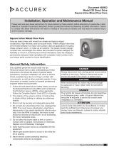
Storage
Fans are protected against damage during shipment. If
the unit cannot be installed and operated immediately,
precautions need to be taken to prevent deterioration
of the unit during storage. The user assumes
responsibility of the fan and accessories while in
storage. The manufacturer will not be responsible
for damage during storage. These suggestions are
provided solely as a convenience to the user.
Indoor
The ideal environment for the storage of fans and
accessories is indoors, above grade, in a low humidity
atmosphere which is sealed to prevent the entry of
blowing dust, rain or snow. Temperatures should be
evenly maintained between 30° to 110°F (-1° to 43°C)
(wide temperature swings may cause condensation
and “sweating” of metal parts). All accessories must be
stored indoors in a clean, dry atmosphere.
Remove any accumulations of dirt, water, ice or snow
and wipe dry before moving to indoor storage. To
avoid “sweating” of metal parts allow cold parts to
reach room temperature. To dry parts and packages
use a portable electric heater to get rid of any moisture
buildup. Leave coverings loose to permit air circulation
and to allow for periodic inspection.
The unit should be stored at least 3 in. (89 mm) off the
floor on wooden blocks covered with moisture proof
paper or polyethylene sheathing. Aisles between parts
and along all walls should be provided to permit air
circulation and space for inspection.
Outdoor
Fans designed for outdoor applications may be stored
outdoors, if absolutely necessary. Roads or aisles for
portable cranes and hauling equipment are needed.
The fan should be placed on a level surface to prevent
water from leaking into the fan. The fan should be
elevated on an adequate number of wooden blocks so
that it is above water and snow levels and has enough
blocking to prevent it from settling into soft ground.
Locate parts far enough apart to permit air circulation,
sunlight and space for periodic inspection. To minimize
water accumulation, place all fan parts on blocking
supports so that rain water will run off.
Do not cover parts with plastic lm or tarps as these
cause condensation of moisture from the air passing
through heating and cooling cycles.
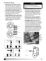
Fan wheels should be blocked to prevent spinning
caused by strong winds.
Inspection and Maintenance During
Storage
While in storage, inspect fans once per month. Keep a
record of inspection and maintenance performed.
If moisture or dirt accumulations are found on parts,
the source should be located and eliminated. At each
inspection, rotate the wheel by hand ten to fteen
revolutions to distribute lubricant on motor. If paint
deterioration begins, consideration should be given to
touch-up or repainting. Fans with special coatings may
require special techniques for touch-up or repair.
Machined parts coated with rust preventive should be
restored to good condition promptly if signs of rust
occur. Immediately remove the original rust preventive
coating with petroleum solvent and clean with lint-
free cloths. Polish any remaining rust from surface
with crocus cloth or ne emery paper and oil. Do not
destroy the continuity of the surfaces. Thoroughly wipe
clean with Tectyl
®
506 (Ashland Inc.) or the equivalent.
For hard to reach internal surfaces or for occasional
use, consider using Tectyl
®
511M Rust Preventive,
WD-40
®
or the equivalent.
Removing From Storage
As fans are removed from storage to be installed
in their nal location, they should be protected and
maintained in a similar fashion until the fan equipment
goes into operation.


 1
1
 2
2
 3
3
 4
4
 5
5
 6
6
 7
7
 8
8


Greenheck Fan Model SWB Series 200 User manual
Greenheck 458341 BDF Operating instructions
Greenheck BSQ-100-3X-QD-DR3 User manual
 Accurex 485953 XID Direct Drive Inline Exhaust Fan User manual
