Page is loading ...

©Copyright LOTRONIC 2018 BEE40-LED Page 2
BEFORE YOU BEGIN
Contents of the carton:
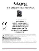
• 1 x Moving head
• 1x Mains lead
• 1x User Manual
• Omega bracket
Unpacking Instructions
Immediately upon receiving a fixture, carefully unpack the carton, check the contents to ensure that all parts are
present and have been received in good condition. Notify the freight company immediately and retain packing
material for inspection if any parts appear to be damaged from shipping or the carton itself shows signs of
mishandling. Keep the carton and all packing materials. In the event that a fixture must be returned to the factory, it
is important that the fixture be returned in the original factory box and packing.
Safety Instructions
Please read these instructions carefully, they include important information about the installation, usage and
maintenance of this product.
• Please keep this User Guide for future reference. If you sell the unit to another user, be sure that he also receives
this instruction booklet.
• Always make sure that you are connecting to the proper voltage, and that the line voltage you are connecting to is
not higher than that stated on the decal or rear panel of the fixture.
• This product is intended for indoor use only!
It is essential that the device is earthed. A qualified person must carry out the electric connection.
• To prevent risk of fire or shock, do not expose fixture to rain or moisture. Make sure there are no flammable
materials close to the unit while operating.
• The unit must be installed in a location with adequate ventilation, at least 20in (50cm) from adjacent surfaces. Be
sure that no ventilation slots are blocked.
• Always disconnect from power source before servicing or replacing fuse and be sure to replace with same fuse size
and type.
• Secure fixture to fastening device using a safety chain. Never carry the fixture solely by its head. Use its carrying
handles.
• Maximum ambient temperature (Ta) is 104° F (40°C). Do not operate the fixture at temperatures higher than this.
• In the event of a serious operating problem, stop using the unit immediately. Never try to repair the unit by
yourself. Repairs carried out by unskilled people can lead to damage or malfunction. Please contact the nearest
authorized technical assistance center. Always use the same type of spare parts.
• Don’t connect the device to a dimmer pack.
• Make sure the power cord is never crimped or damaged.
• Never disconnect the power cord by pulling or tugging on the cord.
• Avoid direct eye exposure to the light source while it is on.
DISCONNECT DEVICE: Where the MAINS plug or an appliance coupler is used as the disconnect device, the
disconnect device shall remain readily operable.
GB

©Copyright LOTRONIC 2018 BEE40-LED Page 3
Features
Rotating bee effect moving head that scans the premises with bright, dynamic beams. The lens is adjustable to rotate
endlessly in 2 directions to create a graphic effect or come together to one single bright beam.
• 4 or 16 DMX channels
• Auto, DMX, master-slave or sound control
• 8 built-in programs, with sound control in DMX mode
• Scan position memory
• 3-color wheel (red, yellow and blue) + open white, rainbow effect
• Narrow beam 5°
• Linear dimmer 0-100%
Specifications
Power supply ........................................................................................ 100-240Vac 50/60Hz
Consumption .................................................................................................................. 55W
Light source .............................................................................................. 4x white 10W LED
Pan/Tilt .......................................................................................... 540°/190° 2 speed levels
Strobe ......................................................................................................................... 0-23Hz
Dimensions ............................................................................................ 245 x 145 x 330mm
Weight ......................................................................................................................... 4.06kg
Mounting
ORIENTATION
This fixture may be mounted in any position
provided there is adequate room for ventilation.
RIGGING
The LED moving head provides a unique mounting
bracket assembly that integrates the bottom of
the base, the included ‘omega bracket’ and the
safety cable rigging point in one unit (see the
illustration on the right).When mounting this
fixture on a truss, be sure to use an appropriate
clamp with the included omega bracket using a
M10 screw fitted through the center hole of the
‘omega bracket’. As an added safety measure, be
sure to attach at least one properly rated safety
cable to the fixture using one of the safety cable
rigging points integrated in the base assembly.
SETUP
Disconnect the power cord before replacing a fuse and always replace with the same type fuse.
Fixture Linking
You will need a serial data link to run light shows of one or more fixtures using a DMX-512 controller or to run
synchronized shows on two or more fixtures set to a master/slave operating mode. The combined number of
channels required by all fixtures on a serial data link determines the number of fixtures that the data link can
support.
Important: Fixtures on a serial/data link must be daisy chained in one single line. Maximum recommended serial
data link distance: 100 meters (1640 ft.) Maximum recommended number of fixtures on a serial data link: 16 fixtures

©Copyright LOTRONIC 2018 BEE40-LED Page 4
Data Cabling
To link fixtures together you must use data cables. If you choose to create your own cable, please use data-grade
cables that can carry a high quality signal and are less prone to electromagnetic interference.
CABLE CONNECTORS
Cabling must have a male XLR connector on one end and a female XLR connector on the other end.
DMX connector configuration
Termination reduces signal errors. To avoid signal transmission problems and interference, it is always advisable to
connect a DMX signal terminator.
CAUTION
Do not allow contact between the common and the fixture’s chassis ground. Grounding the common can cause a
ground loop, and your fixture may perform erratically. Test cables with an ohm meter to check correct polarity and
to make sure the pins are not grounded or shorted to the shield or each other.
3-PIN TO 5-PIN CONVERSION CHART
Note! If you use a controller with a 5-pin DMX output connector, you will need to use a 5-pin to 3-pin adapter.
The chart below details a proper cable conversion:
3 PIN TO 5 PIN CONVERSION CHART
Conductor 3 Pin Female (output) 5 Pin Male (Input)
Ground/Shield Pin 1 Pin1
Data (-) signal Pin 2 Pin 2
Data (+) signal Pin 3 Pin 3
Do not use Do not use
Do not use Do not use
Setting up a DMX Serial Data Link
1. Connect the (male) 3 pin connector side of the DMX cable to the output (female) 3 pin connector of the controller.
2. Connect the end of the cable coming from the controller which will have a (female) 3 pin connector to the input
connector of the next fixture consisting of a (male) 3 pin connector.
3. Then, proceed to connect from the output as stated above to the input of the following fixture and so on.
Display Menu
1
Addr
DMX Address
001-512
2 ChNd DMX Mode
.=CH4
.=CH16
3 SPNd Speed Mode
.=High
.=Low
4 SLNd Run Mode
.=Master
.=Slave
INPUT
COMMON
DMX +
DMX-
Resistance 120 ohm
1/ 4w between pin 2
(DMX-) and pin 3
(DMX+) of the last
fixture.

©Copyright LOTRONIC 2018 BEE40-LED Page 5
5 SHNd Internal Program
.=001
.=002
.=003
.=004
.=005
.=006
.=007
.=008
6 Soun Sound Control
.=OFF
.=ON
7 PAN X Reverse
.=OFF
.=ON
8 TIL Y Reverse
.=OFF
.=ON
9 dISP Display Reverse
.=OFF
.=ON
10 rFAC Reset Default
.=OFF
.=ON
11 Ad t
Home Position
Setting
Delt
Clear Pan and Tilt Home Position(3s)
P(PAN)
.=0-120
t(TILT)
.=0-120
C(Color)
.=0-120
g(Gobo)
.=0-120
12
rST
Reset Motor
Settings
DMX Address
With this function, you can adjust the address from 001 to 512. Press the UP or DOWN button to find your desired
address. Press ENTER to set your desired DMX address.
DMX Channel
The LED moving head has 4CH and 16CH.
Speed Mode
Select between high and low speed
Running Mode
In Running Mode, choose between Master and Slave.
Auto Play
Run one of the 8 built-in programs in Master mode.
Sound
[Music control] With this function, you can run the unit sound-controlled.
Pan Rev: Inversion of the Pan-movement.
Tilt Rev: Inversion of the Tilt -movement.
Display Rev: Inversion of the display.
Factory Reset: Return to factory values. The default setting is OFF.
Home position: With this function, you can Clear PAN and TILT to Home Position after 3s.
Reset Motor: If this function is selected, all motors reset to their original position.

©Copyright LOTRONIC 2018 BEE40-LED Page 6
DMX CHANNELS
4 channel definition table
Channel
DMX Value
Function
1
000-255
Pan
2
000-255
Tilt
3
000-007
Empty
008-047
Auto Play 1
048-087
Auto Play 2
088-127
Auto Play 3
128-167
Auto Play 4
168-207
Auto Play 5
208-247
Auto Play 6
248-255
Color effect Sound Control
4
000-007
Empty
008-032
X/Y auto run 1
033-058
X/Y auto run 2
059-084
X/Y auto run 3
085-110
X/Y auto run 4
111-136
X/Y auto run 5
137-162
X/Y auto run 6
163-188
X/Y auto run 7
189-214
X/Y auto run 8
215-240
X/Y auto run 9
241-255
X/Y Sound Control
16 channel definition table
Channel
DMX Value
Function
1
000-255
Pan
2
000-255
Pan Fine
3
000-255
Tilt
4
000-255
Tilt Fine
5
000-255
P/T Speed
6
000-255
Dimmer(0-100%)
7
000-004
Shutter closed
005-250
Strobe effect slow to fast
251-255
Shutter open
8
000-255
LED1 Dimmer(0-100%)
9
000-255
LED2 Dimmer(0-100%)
10
000-255
LED3 Dimmer(0-100%)
11
000-255
LED4 Dimmer(0-100%)
12
000-017
Open(White)
018-034
White/Red
035-052
Red
053-069
Red/Yellow
070-087
Yellow
088-104
Yellow/Blue
105-122
Blue
123-139
Blue/White
140-195
Backward rotation from fast to slow
196-199
Stop

©Copyright LOTRONIC 2018 BEE40-LED Page 7
200-255
Forward rotation from slow to fast
13
000-133
Effect Lens linear(0~90°)
134-194
Backward rotation from fast to slow
195-255
Forward rotation from slow to fast
14
000-007
Empty
008-047
Auto Play 1
048-087
Auto Play 2
088-127
Auto Play 3
128-167
Auto Play 4
168-207
Auto Play 5
208-247
Auto Play 6
248-255
Color effect Sound Control
15
000-007
Empty
008-032
X/Y auto run 1
033-058
X/Y auto run 2
059-084
X/Y auto run 3
085-110
X/Y auto run 4
111-136
X/Y auto run 5
137-162
X/Y auto run 6
163-188
X/Y auto run 7
189-214
X/Y auto run 8
215-240
X/Y auto run 9
241-255
X/Y Sound Control
16
251-255
RESET(10S)
Fuse Replacement
Locate and remove the unit’s power cord. Once the cord has been removed located the fuse holder located inside the
power socket. Insert a flat-head screw driver into the power socket and gently pry out the fuse holder. Remove the
bad fuse and replace with a new one. The fuse holder has a built-in socket for a spare fuse be sure not to confuse the
spare fuse with active fuse.
Warning: If after replacing the fuse you continue to blow fuses, STOP using the unit. Contact customer support for
further instructions. Continuing to use the unit may cause serious damage.
Cleaning
Due to fog residue, smoke, and dust cleaning the internal and external lenses should be carried out periodically to
optimize light output.
1. Use normal glass cleaner and a soft cloth to wipe down the out-side casing.
2. Clean the external optics with glass cleaner and a soft cloth every 20 days.
3. Always be sure to dry all parts completely before plugging the unit back in.
Page is loading ...
Page is loading ...
Page is loading ...
Page is loading ...
Page is loading ...
Page is loading ...
Page is loading ...
Page is loading ...

©Copyright LOTRONIC 2018 BEE40-LED Page 16
3-PIN AUF 5-PIN UMSETZTABELLE
Hinweis! Wenn Sie ein Steuerpult mit 5-pol. DMX Ausgangsverbinder benutzen, müssen Sie einen 5- auf 3-pol.
Adapter benutzen.
In der nachstehenden Tabelle steht die richtige Kabelumsetzung:
Leiter 3 Pin Buchse (Ausgang) 5 Pin Stecker (Eingang)
Masse/Abschirmung Pin 1 Pin1
Datensignal (-) Pin 2 Pin 2
Datensignal (+) Pin 3 Pin 3
Nicht benutzen Nicht benutzen
Nicht benutzen Nicht benutzen
Einrichten einer seriellen DMX Datenverbindung
1. Den 3-pol. Stecker des DMX Kabels in die 3-pol. Eingangsbuchse des Controllers stecken.
2. Das vom Controller kommende Kabel mit der 3-pol. Buchse an den 3-pol. Eingangsstecker des folgenden Geräts
stecken.
3. Dann den Ausgang des Geräts an den Eingang des folgenden Geräts anschließen usw.
Display Menü
1
Addr
DMX Address
001-512
2 ChNd DMX Mode
.=CH4
.=CH16
3 SPNd Speed Mode
.=High
.=Low
4 SLNd Run Mode
.=Master
.=Slave
5 SHNd Internal Program
.=001
.=002
.=003
.=004
.=005
.=006
.=007
.=008
6 Soun Sound Control
.=OFF
.=ON
7 PAN X Reverse
.=OFF
.=ON
8 TIL Y Reverse
.=OFF
.=ON
9 dISP Display Reverse
.=OFF
.=ON
10 rFAC Reset Default
.=OFF
.=ON
11 Ad t
Home Position
Setting
Delt
Clear Pan and Tilt Home Position(3s)
P(PAN)
.=0-120
t(TILT)
.=0-120
C(Color)
.=0-120
Page is loading ...
Page is loading ...
Page is loading ...
Page is loading ...

©Copyright LOTRONIC 2018 BEE40-LED Page 21
KABELCONNECTOREN
De kabel moet een XLR stekker op één eind en een XLR contra op het andere eind hebben.
DMX connector configuratie
De eindweerstand vermindert signaalfouten. Om transmissie problemen en storingen te voorkomen is het
aanbevolen een DMX signaal eindweerstand aan te sluiten.
Display Menu
1
Addr
DMX Adres
001-512
2 ChNd DMX Modus
.=CH4
.=CH16
3 SPNd Speed Modus
.=High
.=Low
4 SLNd Run Modus
.=Master
.=Slave
5 SHNd Interne Programma
.=001
.=002
.=003
.=004
.=005
.=006
.=007
.=008
6 Soun Geluidsbesturing
.=OFF
.=ON
7 PAN X omkering
.=OFF
.=ON
8 TIL Y omkering
.=OFF
.=ON
9 dISP Display omkering
.=OFF
.=ON
10 rFAC Reset Default
.=OFF
.=ON
11 Ad t Uitgangspositie
Delt
Terug naar uitgangspositie (3s)
P(PAN)
.=0-120
t(TILT)
.=0-120
C(Color)
.=0-120
g(Gobo)
.=0-120
12
rST
Reset Motor
120 ohm weerstand
tussen pin 2 (DMX-) en
pin 3 (DMX+) van de
laatste unit.
Page is loading ...

©Copyright LOTRONIC 2018 BEE40-LED Page 23
251-255
Shutter open
8
000-255
LED1 Dimmer (0-100%)
9
000-255
LED2 Dimmer (0-100%)
10
000-255
LED3 Dimmer (0-100%)
11
000-255
LED4 Dimmer (0-100%)
12
000-017
Open(Wit)
018-034
Wit/Rood
035-052
Rood
053-069
Rood/geel
070-087
geel
088-104
geel/Blauw
105-122
Blauw
123-139
Blauw/wit
192-255
Achteruitdraaiing (snel -> traag)
196-199
Stop
200-255
Vooruitdraaiing traag -> snel
13
000-133
Effect Lens linear(0~90°)
134-194
Achteruitdraaiing (snel -> traag)
195-255
Vooruitdraaiing traag -> snel
14
000-007
Leeg
008-047
Auto Play 1
048-087
Auto Play 2
088-127
Auto Play 3
128-167
Auto Play 4
168-207
Auto Play 5
208-247
Auto Play 6
248-255
Muziekbestuurde kleur
15
000-007
Leeg
008-032
X/Y auto run 1
033-058
X/Y auto run 2
059-084
X/Y auto run 3
085-110
X/Y auto run 4
111-136
X/Y auto run 5
137-162
X/Y auto run 6
163-188
X/Y auto run 7
189-214
X/Y auto run 8
215-240
X/Y auto run 9
241-255
X/Y Muziekbesturing
16
251-255
RESET(10S)
Page is loading ...
Page is loading ...
Page is loading ...
Page is loading ...
Page is loading ...
/


