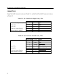
Magtek 90mm Specification
- Category
- Magnetic card readers
- Type
- Specification
This manual is also suitable for
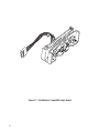
Magtek 90mm is an OEM swipe reader with a TTL level interface, designed for use in retail, access control, and time and attendance environments. It is compliant with industry specifications, including ANSI/ISO Standards 7810, 7811-1 through -6, 7812, 7813, and AAMVA. It has bidirectional read capability and optional integral electronics. Possible use cases include:
- POS systems
- Access control systems
- Time and attendance systems
- Kiosk systems
- Vending machines
- Medical equipment
- Gaming machines


-
 1
1
-
 2
2
-
 3
3
-
 4
4
-
 5
5
-
 6
6
-
 7
7
-
 8
8
-
 9
9
-
 10
10
-
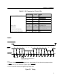 11
11
-
 12
12


Magtek 90mm Specification
- Category
- Magnetic card readers
- Type
- Specification
- This manual is also suitable for
Magtek 90mm is an OEM swipe reader with a TTL level interface, designed for use in retail, access control, and time and attendance environments. It is compliant with industry specifications, including ANSI/ISO Standards 7810, 7811-1 through -6, 7812, 7813, and AAMVA. It has bidirectional read capability and optional integral electronics. Possible use cases include:
- POS systems
- Access control systems
- Time and attendance systems
- Kiosk systems
- Vending machines
- Medical equipment
- Gaming machines
Ask a question and I''ll find the answer in the document
Finding information in a document is now easier with AI
Related papers
-
Magtek Mini Swipe Card Reader Technical Reference Manual
-
-
-
Magtek Rails User manual
-
Magtek MT-215 Technical Reference Manual
-
-
-
-
-
Other documents
-
Compaq 99875320-5 User manual
-
Zebra OEM USB Owner's manual
-
Elo TouchSystems 3000 SERIES User manual
-
Tyco 1529L User manual
-
Elo Touch Solution E812229 User manual
-
-
-
Micro Motion Gas Density Meter - Model 7812 Owner's manual