PVI Industries PV500-34 User manual
- Category
- Water heaters & boilers
- Type
- User manual

PV500-34 05/03 1 Section 34
INSTALLATION & MAINTENANCE MANUAL FOR
QuickDraw
SEMI-INSTANTANEOUS
ENERGY: STEAM TO WATER
U-TUBE SINGLE-WALL & DOUBLE-WALL HEAT EXCHANGERS
DRAIN
FLOOR
DRAIN
FLOOR
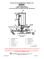
Typical Construction
Figure 34-1
1. U-tube Heat Exchanger 10. Potable Water Inlet
2. Steam Inlet ** 11. Check Valve **
3. Shutoff Valve ** 12. Intratank Circulator *
4. Y-Strainer * 13. Potable Water Outlet
5. Steam Pressure Gauge * 14. Tank Drain Valve
6. Steam Valve 15. Relief Valve
7. Condensate Drain ** 16. Control Enclosure
8. Main Steam Trap *
* Optional
9. Thermostatic Trap
** Not supplied by PVI
(shown with dashed lines)
CAUTION: TEMPERATURES HIGHER THAN 125°F. INCREASE THE RISK OF SCALD INJURY!
IMPORTANT: Clearances for servicing and inspection are 18" at top, sides and rear and a
minimum of one tank diameter in front.
PVI Industries, LLC
• P.O. Box 7124 • Fort Worth, TX 76111
(800) 433-5654 • www.pvi.com

QuickDraw
PV500-34 05/03 Section 34
2
STEAM WITH SINGLE-WALL / DOUBLE-WALL
WARNING! Setting the temperature selector to higher settings provides hotter water
which increases the risk of scald injury. Households with small children or invalids may require a
125°F or lower temperature setting to reduce the risk of scald injury. Allow a few days of operation
at your selected setting to determine the correct temperature setting consistent with your needs.
CONNECTING UNIT
CAUTION
All steam and water supply lines should be
flushed before connecting the unit.
1. Use backup wrenches on all screwed pipe
connections to prevent damage to brazed
joints or studded connections. Shutoff valves
and dielectric unions should be installed in
steam and water lines to allow maintenance
on the unit. Steam supply, water supply and
condensate lines must be supported before
connecting the unit.
ELECTRICAL
The heater is wired for 120 volts and must be electrically grounded in accordance with local codes, or in
the absence of local codes, with the latest edition of the National Electrical Code ANSI/NFPA. When
unit is installed in Canada, it must conform to the CSA C22.1, Canadian Electrical Code, Part 1 and/or
local electrical codes.
1. Branch circuit protection and disconnecting
means must be furnished by the installer.
Refer to the wiring diagram provided with
this unit when installing or troubleshooting
the electrical components of this heater.
2. All wiring must be in accordance with all
local, state, or federal codes.
3. Provide proper overload protection for the
system's circulating pump.
NOTE: Use only copper wire of proper sizing for incoming service. Damage resulting from use
of aluminum wiring will be excluded from coverage under the warranty of this unit.

QuickDraw
PV500-34 05/03 Section 34
3
STEAM WITH SINGLE-WALL / DOUBLE-WALL (con't)
RELIEF VALVE PIPING
The water heater is supplied with a pressure
and temperature relief valve, sized in
accordance with ASME requirements. Each
relief valve should be piped to a suitable floor
drain. No reducing coupling or other restriction
can be installed in the discharge line. It is
strongly recommended that this valve should be
manually operated at least once a year.
WARNING!
Make sure the safety relief valve is piped to
a proper drain per instructions. Scalding
injury and/or water damage can occur from
either the manual lifting of the lever or the
normal operation of the valve if it is not
piped to a proper drain. Insure that the
safety relief valve piping is of the proper
material and rating for the temperature and
pressure of the system and that it is secured
to prevent possible injury. If valve fails to
flow water or reseat, consult the factory. The
relief valve is a primary safety device.
STEAM & CONDENSATE CONNECTIONS
1. The condensate trap controls the discharge of
condensate based on the load on the heat
exchanger, thus preventing the discharge of
live steam through the unit. Appropriately
sized traps are available from your PVI
representative. The steam trap must have a
pressure rating equal or more than the
maximum steam pressure supplied to the
water heater. The trap must also be sized
according to the steam flow shown on the
heater decal.
2. Connect the steam supply to the steam inlet
fitting on the unit as shown in Figure 34-1. A
Y-strainer (100 mesh recommended) must be
installed ahead of and near the unit to prevent
particles of scale and other solids from
damaging the seats of the steam valve. It is
good practice to install a blowdown valve on
the Y-strainer piped to a suitable location that
can be opened at intervals to clean the
strainer screen. A condensate trap may be
located upstream of the steam valve. This trap
will drain the condensate that collects in the
piping and must be plumbed to a suitable
drain or the condensate receiver plumbing.
3. Connect condensate trap inlet at or below the
outlet of the heat exchanger. The ability to lift
condensate via steam pressure cannot be
assured on Quickdraw products due to the
possible use of a modulating steam valve or
multiple solenoid steam control system. The
recommended methods of condensate
distribution are:
a. Plumb to a condensate receiver and
pump or vacuum return to the
condensate return header.
b. Plumb to a pneumatic/electric actuated
condensate pump trap for return to the
condensate return header.
c. Drain to atmosphere – (would require
constant make-up of boiler water).
Inadequate drainage of condensate can
adversely affect heat transfer and limit the
performance of the water heater. Please
note, damage to the water heater attributed
to poor condensate drainage is not covered
in the product warranty.
4. On the Quickdraw semi-instantaneous steam
heater, the 3/4" thermostatic trap must be
plumbed in parallel with the main steam trap
for optimal operation of the heater. It speeds
the removal of air from the heat exchanger
when the steam valve opens. It also serves
the second purpose of a vacuum breaker to
protect the heat exchanger and allow proper
drainage of condensate. (See Figure 34-1.)
5. Locate the thermostatic trap in a tee six
inches above the main condensate line
between the heat exchanger and the main
trap. Plumb its outlet to a point downstream of
the main trap.

QuickDraw
PV500-34 05/03 Section 34
4
STEAM WITH SINGLE-WALL / DOUBLE-WALL (con't)
STEAM VALVES
1. One or more two-position, on-off, electric
valves are used to control the flow of steam.
The valves will return to the closed position
when power is off. This feature will prevent an
excessive temperature buildup in the event of
a power failure. The valve manufacturer’s
operation and maintenance instructions are
shipped with the unit. Refer to these
instructions during start-up and file for future
referencing on maintenance.
CAUTION
Most valve problems are caused by dirt or
trash in the steam line. This is most likely to
occur during installation. Teflon pipe tape,
pipe joint compounds, metal particles and dirt
will clog up strainers and orifices and prevent
valve seats from closing. Clean all pipe line
strainers at start-up and check the valves
again after a few days operation as
recommended by the valve manufacturer.
Inspection of strainers and blowdown piping
should be part of the normal maintenance
routine on this equipment.
OPTIONAL SAFETY SYSTEMS
1. This heater may be supplied with a pressure
gradient monitoring (PGM) system,
consisting of a differential pressure switch, a
delay timer and a steam purge valve. It
serves as a safety system to prevent the
contamination of potable water with steam.
The pressure switch monitors both steam
and potable water system pressure. If the
potable water pressure falls to a point
slightly above the steam pressure and stays
there for a short period of time, then the
heater shuts down, closes the steam valve
and opens a steam purge valve to quickly
reduce the steam pressure in the heat ex-
changer. The system requires a manual
reset to begin operation again. Note that
the system does not necessarily detect a
leak, but it prevents steam from entering the
potable water if there is a leak.
2. Another safety option is the tank purge
system (sometimes called a double solenoid
safety system). The tank temperature is
monitored and if it exceeds an adjustable
limit, the heater is shut down and a valve
opens to dump the overheated water. This
allows cold make-up water to enter the tank
and quickly reduce the tank temperature.
START-UP OPERATION
1. After all the steam, condensate and water
lines are installed and inspected, the steam
supply source and the condensate receiver
should be checked for correct operation.
Steam supply pressure to the heater must be
equal to or less than the supply pressure on
the heater decal. A pressure reducing valve
can be installed in the supply line to meet this
requirement.
2. Steam is directed to the heat exchanger
through a header and steam control valves.
The steam control valves are normally closed,
on-off, electric valves and solenoid-operated.
Should an electrical power failure occur,
steam valves will close and stop steam flow to
the unit.
WARNING!
Excessive steam pressure can cause the
steam valve(s) and condensate trap to
malfunction and can cause the heat transfer
rate to exceed the relief valve capacity which
can result in an explosion causing damage,
injury or death.

QuickDraw
PV500-34 04/03 5 Section 34
STEAM WITH SINGLE-WALL / DOUBLE-WALL (con't)
START-UP PROCEDURE
1. Fill tank with water; open relief valve to
purge air from top of tank. Check for
plumbing leaks.
2. Push control switch, located on the control
box, to activate the steam valve and
thermostats. Check steam valve for
operation; the valve solenoid should “click”
to open valves when operating switch is
pushed “on”. The tank circulating pump, if
present, should also operate. Check
thermostat settings. The temperature
limiting device is set at 200°F. Temperature
setting: The operating thermostat is set at
the factory at approximately 130°F and the
upper operating thermostat is set at
approximately 125°F. Adjustment may be
made by turning the operating thermostat
dial to the desired temperature.
3. Push the operating switch, located on the
control box, to “off” before opening manual
main steam supply valve. This will allow
condensate that has collected in the supply
line to drain through the trap installed in
front of the steam valve. When the steam
supply line is free of condensate, push
operating switch to “on”, opening the electric
on-off steam valves allowing steam to flow
through the heat exchanger.
4. Open nearby hot water tap to maintain a
flow of water through tank when starting up
units. Observe condensate flow at the
receiver or other collection site to verify
satisfactory flow. Regulate flow of water
through tank to allow steam valve to cycle
off and on, and check operation of unit.
MAINTENANCE
1. A preventive maintenance program should
be established to assure a long, trouble-free
life for the water heater.
2. Scale will normally form in the tank during
operation and will accumulate on the bottom
of the tank. The scale is formed from the
natural chemicals in the water that
precipitate out during the heating cycles.
Some water supplies contain more of these
chemicals than others, and the scale
buildup will occur more rapidly. Other
factors affecting the scale buildup are the
amount of hot water used and the
temperature of the water. The more hot
water used, the more fresh water containing
the scale-forming chemicals is brought into
the tank. As the temperature of the water
increases, the rate of scale deposited will be
increased. The unit should be inspected and
cleaned as required by local water
conditions.
CAUTION
The relief valve is a primary safety device.
3. It is required for safe practice to operate the
temperature and pressure relief valve once
a year by lifting the lever briefly. If the valve
does not open and close properly when
testing, it must be replaced.
4. The temperature limiting device and
thermostat temperature sensors that extend
into the water in the tank may become
coated with scale, depending on the type of
water in your area. This coating will affect
accuracy of sensors and can allow water
temperature to exceed the desired limits.
These controls should be removed from
tank and inspected at necessary intervals.
Remove scale if present.
WARNING!
To reduce the risk of electrical shock injury
or death, on control systems using 120 volt
external power, be certain switch is off and
power disconnected before work is
performed on this heater.

QuickDraw
PV500-34 05/03 6 Section 34
STEAM WITH SINGLE-WALL / DOUBLE-WALL (con't)
TROUBLESHOOTING NOTES
Problem:
1. No hot water at even low flow
a. Cause: Steam valve(s) not opening
Solution: Check that electrical coils are energized. If not, trace wiring problem. If so, the valve
may be faulty, the steam pressure inadequate to open the valve (< 5 psi depending on the
valve), or the linkage (if applicable) is out of adjustment.
b. Cause: Condensate flow is blocked
Solution: Float-type traps will not open if the inlet steam pressure exceeds the trap rating.
Check steam pressure against the rating stamped on the trap. Check that there are no valves or
clogged strainers between the heat exchanger and the condensate receiver.
c. Cause: PGM system tripped
Solution: The pressure gradient monitoring option prevents the steam valve from opening if the
water pressure in the tank is within 10 psi of the steam pressure. Correct water pressure
problem.
Problem:
2. Heater recovery is slow or outlet temperature is below setpoint:
a. Cause: Steam supply insufficient
Solution: Loss of steam delivery pressure, see below.
b. Cause: Condensate not draining
Solution: Check that there is not excessive condensate lift. For low pressure steam, any lift at
all may affect performance. Check the sizing of the trap. Check that the condensate receiver is
not pressurized. Check that there is no blockage in the condensate line from the trap to the
receiver. Unclog any strainers in the system.
c. Cause: Condensate trap not operating
Solution: If the condensate temperature near the heat exchanger is considerably less than the
steam temperature, then condensate is being backed up into the heat exchanger. Check that
the supply steam pressure does not exceed the trap pressure rating. Check the trap for
blockage or mechanical failure. Check that the trap is sized sufficiently for the load.
d. Cause: Heat exchanger is breached
Solution: If excessive condensate is draining, the heat exchanger may have a leak and be
filling with water.
e. Cause: Heat exchanger is fouled
Solution: Inspect the heat exchanger for excessive scaling or fouling on the water side.
f. Cause: Abnormal operating conditions
Solution: The water temperature has a significant effect on the efficiency of the heat
exchanger. Check if the setpoint is higher than specified. Confirm the measured flow rate with
meters or by volume and rate. Check that there are no other loads on the heater.
Problem:
3. Steam delivery pressure to heat exchanger is low or drops off:
a. Cause: Low supply steam pressure.
Solution: Unclog strainer. Check for blockage or restrictions in the line between the boiler and
the water heater. Check for low boiler output or upstream blockage and make necessary
corrections.

QuickDraw
PV500-34 05/03 7 Section 34
STEAM WITH SINGLE-WALL / DOUBLE-WALL (con't)
b. Cause: Steam valve(s) not fully opening
Solution: Check steam pressure before and after steam valve. The pressure drop should not
be more than half of the inlet pressure. Check valve for blockage. Check linkage for adjustment.
Check modulating signal (if applicable). Check the supplied voltage to the valve coil.
c. Cause: Piping flow restricted.
Solution: Calculate the flow velocity and expected friction loss. If excessive, larger inlet and
outlet piping are necessary.
d. Cause: Main valve malfunction.
Solution: Refer to the valve manual for instructions on main valve repair.
e. Cause: Main valve undersized.
Solution: Check steam pressure before and after steam valve. Check valve capacity against
the load. If insufficient, increase trim or valve size.
Problem:
4. Outlet water temperature not constant.
a. Cause: Insufficient recovery
Solution: If the thermostat or controller is always open, then the outlet temperature will vary
with load. See above for causes of insufficient recovery.
b. Cause: Malfunctioning thermostat
Solution: Measure the tank temperature near the thermostat and compare to setpoint. The
thermostat should turn on and off within 5°F of setpoint.
Problem:
5. Unusual noises coming from heater.
a. Cause: Flashing condensate
Solution: Pinging, rattling or banging noises are usually the result of condensate flashing to
steam. Condensate not draining properly. Check that there is not excessive condensate lift.
Check the sizing of the trap. Check that the condensate receiver is not pressurized. Check that
there is no blockage in the condensate line from the trap to the receiver. Unclog any strainers in
the system.
Problem:
6. Heat exchanger visibly leaking.
a. Cause: Plumbing connection loose
Solution: Check and tighten plumbing connection.
b. Cause: Double-wall heat exchanger tube leak
Solution: If one of the tube walls is breached, a double-wall heat exchanger will leak at the
joint between the tubesheets. Isolate the heater and replace the heat exchanger.
Since PVI cannot control the use of the water heater, water conditions, or maintenance, the
warranty on the water heater does not cover poor performance, structural failure,
or leaking due to an excessive accumulation of scale.
-
 1
1
-
 2
2
-
 3
3
-
 4
4
-
 5
5
-
 6
6
-
 7
7


PVI Industries PV500-34 User manual
- Category
- Water heaters & boilers
- Type
- User manual
Ask a question and I''ll find the answer in the document
Finding information in a document is now easier with AI
Related papers
-
PVI Industries QuickDraw PV500-24 User manual
-
PVI Industries QuickDraw Semi-Instantaneous and Storage Installation guide
-
PVI Industries EZ Plate Semi-Instantaneous and Storage Installation guide
-
PVI Industries EZ Plate Storage Installation guide
-
-
-
PVI Industries PV 19A Startup Manual
-
PVI Industries QuickDraw Water-to-Water Storage Installation guide
-
-
Other documents
-
 TLV SR-3 User manual
-
 Patterson-Kelley P-K Compact User manual
-
 DriSteem STS Series Installation, Operation and Maintenance Manual
-
Hubbell STH User manual
-
Yarway Industrial Steam Trapping Handbook User guide
-
Lochinvar Hot Water Generator Operating instructions
-
-
-
A.O. Smith Commercial Semi-Instantaneous Technical Documents
-
Condair 2553855-C SE Series User manual


