Page is loading ...

SAFETY WARNING
Only qualified personnel should install and service the equipment. The installation, starting up, and servicing of heating, ventilating, and air-
conditioning equipment can be hazardous and requires specific knowledge and training. Improperly installed, adjusted or altered equipment
by an unqualified person could result in death or serious injury. When working on the equipment, observe all precautions in the literature and
on the tags, stickers, and labels that are attached to the equipment.
Performance Climate Changer Air Handler
Model UCCA
Sizes 3-30
*X39641253010*
Installation, Operation
and Maintenance
X-39641253010
CLCH-SVX009A-EN
January 2014

© 2014 Trane All rights reserved CLCH-SVX009A-EN
Warnings, Cautions and Notices
Warnings, Cautions and Notices.
Note that warnings,
cautions and notices appear at appropriate intervals
throughout this manual. Warnings are provided to alert
installing contractors to potential hazards that could result
in death or personal injury. Cautions are designed to alert
personnel to hazardous situations that could result in
personal injury, while notices indicate a situation that
could result in equipment or property-damage-only
accidents.
Your personal safety and the proper operation of this
machine depend upon the strict observance of these
precautions.
Read this manual thoroughly before operating or servicing
this unit.
Important
Environmental Concerns!
Scientific research has shown that certain man-made
chemicals can affect the earth’s naturally occurring
stratospheric ozone layer when released to the
atmosphere. In particular, several of the identified
chemicals that may affect the ozone layer are refrigerants
that contain Chlorine, Fluorine and Carbon (CFCs) and
those containing Hydrogen, Chlorine, Fluorine and
Carbon (HCFCs). Not all refrigerants containing these
compounds have the same potential impact to the
environment. Trane advocates the responsible handling of
all refrigerants-including industry replacements for CFCs
such as HCFCs and HFCs.
Responsible Refrigerant Practices!
Trane believes that responsible refrigerant practices are
important to the environment, our customers, and the air
conditioning industry. All technicians who handle
refrigerants must be certified. The Federal Clean Air Act
(Section 608) sets forth the requirements for handling,
reclaiming, recovering and recycling of certain
refrigerants and the equipment that is used in these
service procedures. In addition, some states or
municipalities may have additional requirements that
must also be adhered to for responsible management of
refrigerants. Know the applicable laws and follow them.
ATTENTION:
Warnings, Cautions, and Notices appear at
appropriate sections throughout this literature. Read
these carefully:
WARNING
Indicates a potentially hazardous
situation which, if not avoided, could
result in death or serious injury.
CAUTION
s
Indicates a potentially hazardous
situation which, if not avoided, could
result in minor or moderate injury. It
could also be used to alert against
unsafe practices.
NOTICE:
Indicates a situation that could result in
equipment or property-damage only
accidents.
WARNING
Proper Field Wiring and Grounding
Required!
All field wiring MUST be performed by qualified
personnel. Improperly installed and grounded field
wiring poses FIRE and ELECTROCUTION hazards. To
avoid these hazards, you MUST follow requirements for
field wiring installation and grounding as described in
NEC and your local/state electrical codes. Failure to
follow code could result in death or serious injury.
WARNING
Personal Protective Equipment (PPE)
Required!
Installing/servicing this unit could result in exposure to
electrical, mechanical and chemical hazards.
• Before installing/servicing this unit, technicians
MUST put on all Personal Protective Equipment (PPE)
recommended for the work being undertaken.
ALWAYS refer to appropriate MSDS sheets and OSHA
guidelines for proper PPE.
• When working with or around hazardous chemicals,
ALWAYS refer to the appropriate MSDS sheets and
OSHA guidelines for information on allowable
personal exposure levels, proper respiratory
protection and handling recommendations.
• If there is a risk of arc or flash, technicians MUST put
on all Personal Protective Equipment (PPE) in
accordance with NFPA 70E or other country-specific
requirements for arc flash protection, PRIOR to
servicing the unit.
Failure to follow recommendations could result in death
or serious injury.

Warnings, Cautions and Notices
CLCH-SVX009A-EN 3
Performance air handler model UCCA is not designed for
use with UV lights.
WARNING
Harmful Ultraviolet (UV) Lights!
Failure to follow instructions below could result in
death or serious injury and equipment damage.
Do not field install ultraviolet lights in this air handling
unit for the intended purpose of improving indoor air
quality. High intensity C-band ultraviolet light is known
to severely damage polymer (plastic) materials and
poses a personal safety risk to anyone exposed to the
light without proper personal protective equipment
(can cause damage to eyes and skin). Polymer materials
commonly found in HVAC equipment that may be
susceptible include insulation on electrical wiring, fan
belts, thermal insulation, various fasteners and
bushings. Trane accepts no responsibility for the
performance or operation of our air handling equipment
in which ultraviolet devices were installed outside of
the Trane factory.

4 CLCH-SVX009A-EN
Table of Contents
Warnings, Cautions and Notices . . . . . . . . . . 2
Introduction . . . . . . . . . . . . . . . . . . . . . . . . . . . . . 6
Overview of Manual
. . . . . . . . . . . . . . . . . . . 6
Nameplate
. . . . . . . . . . . . . . . . . . . . . . . . . . . . 6
General Information
. . . . . . . . . . . . . . . . . . . . . 7
Operating Environment
. . . . . . . . . . . . . . . . 7
Unit Description
. . . . . . . . . . . . . . . . . . . . . . . 7
Factory-Mounted Controls . . . . . . . . . . . . . 8
Wiring . . . . . . . . . . . . . . . . . . . . . . . . . . . . . 8
Model Number Description
. . . . . . . . . . . . . . . 9
Pre-Installation
. . . . . . . . . . . . . . . . . . . . . . . . . 12
Receiving and Handling
. . . . . . . . . . . . . . . 12
Inspection . . . . . . . . . . . . . . . . . . . . . . . . . 12
Packaging/Shipping . . . . . . . . . . . . . . . . . 12
Identification . . . . . . . . . . . . . . . . . . . . . . . 12
Handling . . . . . . . . . . . . . . . . . . . . . . . . . . 12
Receiving Checklist . . . . . . . . . . . . . . . . . 12
Jobsite Storage
. . . . . . . . . . . . . . . . . . . . . . 12
Outdoor Storage . . . . . . . . . . . . . . . . . . . . 12
Long-Term Storage . . . . . . . . . . . . . . . . . 13
Site Preparation
. . . . . . . . . . . . . . . . . . . . . . 13
Dimensions and Weights
. . . . . . . . . . . . . . . . 14
Service Clearances
. . . . . . . . . . . . . . . . . . . . 14
Fans
. . . . . . . . . . . . . . . . . . . . . . . . . . . . . . . . 17
Motors
. . . . . . . . . . . . . . . . . . . . . . . . . . . . . . 17
Installation - Mechanical
. . . . . . . . . . . . . . . . 19
Lifting and Rigging
. . . . . . . . . . . . . . . . . . . 19
Remove Shipping Tie-Downs . . . . . . . . . 19
General Lifting Considerations . . . . . . . . 20
Skid Removal . . . . . . . . . . . . . . . . . . . . . . 21
Forklifting Considerations . . . . . . . . . . . . 21
Unit Placement and Assembly
. . . . . . . . . . 22
Unit Placement . . . . . . . . . . . . . . . . . . . . . 22
Floor Mounting . . . . . . . . . . . . . . . . . . . . . 22
Ceiling Suspension . . . . . . . . . . . . . . . . . 22
Unit Assembly . . . . . . . . . . . . . . . . . . . . . 23
Joining at Shipping Splits . . . . . . . . . . . . 23
Fan Removal . . . . . . . . . . . . . . . . . . . . . . . 24
Filter Placement . . . . . . . . . . . . . . . . . . . . .26
Duct Connections
. . . . . . . . . . . . . . . . . . . . . .27
Condensate Drain Connections . . . . . . . .27
Fan Discharge Connections . . . . . . . . . . . .28
Field Conversions
. . . . . . . . . . . . . . . . . . . . .28
Fan Discharge Conversion . . . . . . . . . . . .28
Adjusting the Isolators . . . . . . . . . . . . . . . .29
Coil Piping and Connections
. . . . . . . . . . . . . .30
General Recommendations
. . . . . . . . . . . . .30
Drain Pan Trapping
. . . . . . . . . . . . . . . . . . . .30
Steam Coil Piping
. . . . . . . . . . . . . . . . . . . . .31
Water Coil Piping
. . . . . . . . . . . . . . . . . . . . . .33
Refrigerant Coil Piping
. . . . . . . . . . . . . . . . .34
Liquid Lines
. . . . . . . . . . . . . . . . . . . . . . . . . .35
Suction Lines
. . . . . . . . . . . . . . . . . . . . . . . . .36
Expansion Valves
. . . . . . . . . . . . . . . . . . . . . .36
Hot Gas Bypass
. . . . . . . . . . . . . . . . . . . . . . .36
Remodel, Retrofit, or Replacement
. . . . . . .37
Field-Installed Evaporator Piping Examples .
38
Electrical Requirements
. . . . . . . . . . . . . . . . . .43
Unit Wiring Diagrams . . . . . . . . . . . . . . . .43
Supply Power Wiring . . . . . . . . . . . . . . . . .43
Electrical Grounding Restrictions . . . . . . .43
Fuse Sizes . . . . . . . . . . . . . . . . . . . . . . . . . .44
VFD Wiring Schematic . . . . . . . . . . . . . . . .45
Start-Up
. . . . . . . . . . . . . . . . . . . . . . . . . . . . . . . .48
Pre-Startup Checklist
. . . . . . . . . . . . . . . . . . .48
General Checks . . . . . . . . . . . . . . . . . . . . . .48
Fan-Related Checks . . . . . . . . . . . . . . . . . .48
Coil-Related Checks . . . . . . . . . . . . . . . . . .48
Motor-Related Checks . . . . . . . . . . . . . . . .49
Unit Operation
. . . . . . . . . . . . . . . . . . . . . . . .49
Calculate Motor Voltage Imbalance . . . . .49
VFD Programming Parameters . . . . . . . . .49
Tension the Fan Belt . . . . . . . . . . . . . . . . .51
Determine Fan Speed . . . . . . . . . . . . . . . .52
Align Fan and Motor Sheaves . . . . . . . . . .53
Check Multiple Belts . . . . . . . . . . . . . . . . .53

CLCH-SVX009A-EN 5
External Insulating Requirements
. . . . . . . 53
Routine Maintenance
. . . . . . . . . . . . . . . . . . . 54
Maintenance Checklist
. . . . . . . . . . . . . . . . 54
Air Filters
. . . . . . . . . . . . . . . . . . . . . . . . . . . . 55
Throwaway Filters . . . . . . . . . . . . . . . . . . 55
Coils
. . . . . . . . . . . . . . . . . . . . . . . . . . . . . . . . 55
Steam and Water Coils . . . . . . . . . . . . . . 55
Refrigerant Coils . . . . . . . . . . . . . . . . . . . . 56
Coil Winterization . . . . . . . . . . . . . . . . . . . 57
Moisture Purge Cycle . . . . . . . . . . . . . . . . 57
Drain Pans
. . . . . . . . . . . . . . . . . . . . . . . . . . . 58
Low Limit Switch
. . . . . . . . . . . . . . . . . . . . . 58
Fans
. . . . . . . . . . . . . . . . . . . . . . . . . . . . . . . . 60
Inspecting and Cleaning Fans . . . . . . . . . 60
Bearing Set Screw Alignment . . . . . . . . . 60
Torque Requirements . . . . . . . . . . . . . . . 61
Fan Bearing Lubrication . . . . . . . . . . . . . . 61
Motor Bearing Lubrication . . . . . . . . . . . 61
Fan Motor Inspection . . . . . . . . . . . . . . . . 61
Troubleshooting
. . . . . . . . . . . . . . . . . . . . . . . . 62

6 CLCH-SVX009A-EN
Introduction
Overview of Manual
Use this manual to install, startup, operate, and maintain
the Performance Climate Changer™ air handler model
UCCA. Carefully review the procedures discussed in this
manual to minimize installation and startup difficulties.
Nameplate
Each Performance air handler section includes one or
more nameplate/label (see Figure 1), which identifies the
type of section and functional components, customer
tagging information, the unit serial number, the unit order
number, the build-section position for installation, and the
unit model number.
Note: The unit serial number and order number is
required when ordering parts or requesting service
for a Trane air handler.
Figure 1. Performance air handler section nameplate
Agency listings and/or
agency certifications
Trane order number
Unit level serial number
Service model number
Unit tagging
Section location
Functional section type
Notes and additional
section information

General Information
CLCH-SVX009A-EN 7
General Information
Operating Environment
Performance Climate Changer™ air handler model UCCA
is designed for indoor applications. When considering the
placement of the air handler, it is important to consider the
operating environment. The acceptable ambient
temperature range for unit operation is -40ºF to 140ºF
(-40ºC to 60ºC).
Do not operate unit above maximum fan speed or unit
airflow as shown in the unit fan curves. (See CLCH-
PRC024A-EN Performance Climate Changer Air Handler
Model UCCA catalog.) Unit operation at greater than
maximum fan speed can drastically reduce bearing life
and result in a catastrophic failure. Operating at greater
than the maximum allowable airflow in the cooling mode
may result in unsatisfactory operation due to moisture
carryover from the coil. In addition, it is often not
economical to operate a unit at its maximum fan speed
due to the greater motor power requirements.
Do not operate units with electric heat below the minimum
airflow listed (see Table 11, page 44). This is to prevent
excessive leaving air temperatures and electric heat limit
trips.
Do not operate a hydronic (or steam) coil and electric heat
simultaneously. This is to prevent excessive leaving air
temperatures and limit trips. Electric heat units are
equipped with a lockout switch to disable the electric
heater if the temperature of the hydronic (or steam) coil is
greater than 95°F (35C).
For heating applications, a special motor may be required
to withstand the higher temperatures. Motors with Class B
insulation are acceptable for ambient temperatures up to
104º F, while motors with Class F insulation can withstand
ambient temperatures to +140º F (60º C).
Note: Units with UL approval have a maximum ambient
temperature requirement of 104ºF. The customer
should provide adequate freeze protection for the
coils. See “Routine Maintenance,” page 54 for
more information.
Unit Description
The Performance air handler model UCCA is designed for
budget-conscience applications, but does not sacrifice on
construction, quality, or performance.
• 2-inch R13 foam insulated panels and doors
• Less than 0.005 inches at +/-4 inches w.g. panel and
door deflection
• All airfoil bladed dampers meet ASHRAE 90.1 lowest
specified leakage
• Quick-connect wiring minimizes installation costs and
provides wiring integrity between sections
• Factory engineered and mounted control packages
• Hinged and handled access doors
• UL/CUL listed
• AHRI Standard 430-certified air-handling unit
• AHRI Standard 410-certified coils
• 2-inch/4-inch combination filter, or 2-inch/4-inch
combination filter in a mixing box
• Fan options including forward curved (FC) and direct-
drive plenum (DDP) fans
• Electric heat including full modulating control
• Units ship on skid for forklift transportation at job site
• Building Information Modeling (BIM) drawing to
minimize jobsite ductwork, electrical, piping, and
structural interference
For more information, refer to the following documents,
available from your local Trane sales engineer:
• CLCH-PRC024A-EN, Performance Climate Changer™
Air Handler Model UCCA catalog
• CLCH-PRG004-EN, Performance Climate Changer™
Air handler Model UCCA guide specifications
• CLCH-SLB022-EN, Performance Climate Changer™ Air
Handlers for Every Need sales brochure

General Information
8 CLCH-SVX009A-EN
Factory-Mounted Controls
Performance air handlers are available with an optional
control interface. This package can be used as part of a
stand-alone operation, or it can be fully integrated into a
comprehensive control system. The Trane Earthwise™
system incorporates the benefits of factory-installed
controls and links the air handler to the Tracer™ SC system
controls building management system. This option is
designed to lower installation costs and risk while
dramatically improving the quality of the application and
the performance of the air handler. The entire air handler
control system is engineered, mounted, wired, and tested
before leaving the factory. As a result of strict quality
manufacturing methods, these control options bring
consistency and reliability to the control-system package
and provide single-source responsibility.
The following control devices are available as standard
mounted on fan sections:
• Variable-frequency drives (VFDs)
• Control interface package
– Fan motor disconnect switch
– Fused transformer(s)
– Fan contactor
– Customer terminal strip for field-provided controls
• Various end device options, including:
– Low limit protection
– Condensate overflow switch
– Fan status switch
– Filter status switch
– Discharge air sensor
– Mixed air sensor
– Damper actuator
Wiring
Entrances are generally provided for field-installation of
high and low voltage wiring through a pipe/nipple
connection in the unit depending on unit configuration
with or without factory-mounted controls. Before
installation, consider overall unit serviceability and
accessibility before mounting, running wires (power),
making penetrations, or mounting any components to the
cabinet.
Wiring to the air handler must be provided by the installer
and must comply with all national and local codes. The fan
motor nameplate includes a wiring diagram. If there are
any questions concerning the wiring of the motor, write
down the information on the motor nameplate and contact
your local Trane sales office.
WARNING
Proper Field Wiring and Grounding
Required!
All field wiring MUST be performed by qualified
personnel. Improperly installed and grounded field
wiring poses FIRE and ELECTROCUTION hazards. To
avoid these hazards, you MUST follow requirements for
field wiring installation and grounding as described in
NEC and your local/state electrical codes. Failure to
follow code could result in death or serious injury.

CLCH-SVX009A-EN 9
Digit 1, 2, 3, 4— Unit Model
UCCA = Performance Climate Changer
Air Handler
Digit 5 - Configuration
A = Horizontal/front top with housed fan
B = Horizontal/top front with housed fan
C = Vertical/front top with housed fan
D = Vertical/top front with housed fan
E = Vertical/back top with housed fan
F = Vertical/top back with housed fan
G = Horizontal/front top with DDP fan
H = Horizontal/top front with DDP fan
S = Special
Digit 6, 7 - Unit size
03 = Unit size 3
06 = Unit size 6
08 = Unit size 8
10 = Unit size 10
12 = Unit size 12
14 = Unit size 14
17 = Unit size 17
21 = Unit size 21
25 = Unit size 25
30 = Unit size 30
Digit 8 - Unit voltage
0 = No motor, controls, or electric heat
A = 208 volt/60 hertz/3 phase odp
B = 230 volt/60 hertz/3 phase odp
C = 460 volt/60 hertz/3 phase odp
D = 575 volt/60 hertz/3 phase odp
S = Special
Digit 9 - Open
0 = Open for future use
Digit 10, 11 - Design sequence
A0 = A0
Digit 12 - Connections
R = Polymer drain pan, RH coil/RH motor
L = Polymer drain pan, LH coil/LH motor
C = Polymer drain pan, RH coil/LH motor
D = Polymer drain pan, LH coil/RH motor
E = Stainless steel drain pan, RH coil/
RH motor
F = Stainless steel drain pan, LH coil/
LH motor
G = Stainless steel drain pan, RH coil/
LH motor
H = Stainless steel drain pan, LH coil/
RH motor
S = Special
Digit 13 - Coil #1 first in
airstream
0 = No unit coil #1
A = 1 row preheat hydronic/9 fins per in.
B = 1 row preheat hydronic/12 fins per in.
C = 1 row preheat hydronic/14 fins per in.
D = 2 row preheat hydronic/9 fins per in.
E = 2 row preheat hydronic/12 fins per in.
F = 2 row preheat hydronic/14 fins per in.
G = 1 row preheat steam/6 fins per in.
H = 4 row hydronic/9 fins per in.
J = 4 row hydronic/12 fins per in.
K = 4 row hydronic/14 fins per in.
L = 6 row hydronic/9 fins per in.
M = 6 row hydronic/12 fins per in.
N = 6 row hydronic/14 fins per in.
P = 8 row hydronic/9 fins per in.
R = 8 row hydronic/12 fins per in.
T = 8 row hydronic/14 fins per in.
U = 4 row DX/9 fins per in.
V = 4 row DX/12 fins per in.
W = 4 row DX/14 fins per in.
Y = 6 row DX/9 fins per in.
Z = 6 row DX/12 fins per in.
1 = 6 row DX/14 fins per in.
S = Special
Digit 14 - Coil #2 second in
airstream
0 = No unit coil #2
A = 1 row reheat hydronic/9 fins per in.
B = 1 row reheat hydronic/12 fins per in.
C = 1 row reheat hydronic/14 fins per in.
D = 2 row reheat hydronic/9 fins per in.
E = 2 row reheat hydronic/12 fins per in.
F = 2 row reheat hydronic/14 fins per in.
G = 1 row reheat steam/6 fins per in.
H = 4 row hydronic/9 fins per in.
J = 4 row hydronic/12 fins per in.
K = 4 row hydronic/14 fins per in.
L = 6 row hydronic/9 fins per in.
M = 6 row hydronic/12 fins per in.
N = 6 row hydronic/14 fins per in.
P = 8 row hydronic/9 fins per in.
R = 8 row hydronic/12 fins per in.
T = 8 row hydronic/14 fins per in.
U = 4 row DX/9 fins per in.
V = 4 row DX/12 fins per in.
W = 4 row DX/14 fins per in.
Y = 6 row DX/9 fins per in.
Z = 6 row DX/12 fins per in.
1 = 6 row DX/14 fins per in.
S = Special
Digit 15 - Coil options
0 = None
1 = Aluminum fin, galvanized coil casing
2 = Aluminum fin, stainless steel coil
casing
S = Special
Digit 16 - Controller options
0 = None
1 = Unwired end devices
2 = Control interface
S = Special
Digit 17 - Electric heat/factory
mounted
0 = No electric heat
1 = Electric heat with 1 stage
2 = Electric heat with 2 stages
4 = Electric heat with 4 stages
5 = SSR control
S = Special
Digit 18, 19, 20 - Electric
heater kW
000 = None
006 = 6.0 kW
007 = 7.0 kW
008 = 8.0 kW
009 = 9.0 kW
010 = 10.0 kW
011 = 11.0 kW
012 = 12.0 kW
013 = 13.0 kW
014 = 14.0 kW
015 = 15.0 kW
016 = 16.0 kW
017 = 17.0 kW
018 = 18.0 kW
020 = 20.0 kW
022 = 22.0 kW
024 = 24.0 kW
026 = 26.0 kW
027 = 28.0 kW
030 = 30.0 kW
032 = 32.0 kW
034 = 34.0 kW
036 = 36.0 kW
038 = 38.0 kW
041 = 41.0 kW
044 = 44.0 kW
047 = 47.0 kW
050 = 50.0 kW
053 = 53.0 kW
056 = 56.0 kW
059 = 59.0 kW
063 = 63.0 kW
067 = 67.0 kW
071 = 71.0 kW
075 = 75.0 kW
079 = 79.0 kW
083 = 83.0 kW
087 = 87.0 kW
091 = 91.0 kW
095 = 95.0 kW
100 = 100 kW
105 = 105 kW
110 = 110 kW
115 = 115 kW
120 = 120 kW
SSS = Special
Digit 21 - Electric heat options
0 = None
A = Line fuse, door interlocking
disconnect switch and airflow switch
S = Special
Model Number Description

10 CLCH-SVX009A-EN
Model Number Description
Digit 22 - Refrigerant circuit
options
0 = None
1 = Single refrigerant circuit arr with
1 stage DX 1/4-in. distributor
2 = Face split refrigerant circuit arr with
2 stage DX 1/4-in. distributor
3 = Intertwined refrigerant circuit arr with
2 stage DX 1/4-in. distributor
4 = Single refrigerant circuit arr with
2 stage DX 1/4-in. distributor
5 = Face split refrigerant circuit arr with
4 stage DX 1/4-in. distributor
6 = Intertwined refrigerant circuit arr with
4 stage DX 1/4-in. distributor
A = Single refrigerant circuit arr with
1 stage DX 3/16-in. distributor
B = Face split refrigerant circuit arr with
2 stage DX 3/16-in. distributor
C = Intertwined refrigerant circuit arr with
2 stage DX 3/16-in. distributor
D = Single refrigerant circuit arr with
2 stage DX 3/16-in. distributor
E = Face split refrigerant circuit arr with
4 stage DX 3/16-in. distributor
F = Intertwined refrigerant circuit arr with
4 stage DX 3/16-in. distributor
S = Special
Digit 23 - Motor horsepower
0 = No motor
A = 1 hp (0.746 kW)
B = 1 1/2 hp (1.119 kW)
C = 2 hp (1.492 kW)
D = 3 hp (2.238 kW)
E = 5 hp (3.730 kW)
F = 7 1/2 hp (5.595 kW)
G = 10 hp (7.460 kW)
H = 15 hp (11.190 kW)
S = Special
Digit 24 - Volume control
0 = None
A = FC fan constant volume with variable
pitch sheaves
B = FC fan constant volume with fixed
pitch sheaves or DDP fan
C = FC fan with fixed pitch sheaves or
DDP fan and variable frequency drive
D = FC fan with fixed pitch sheaves or
DDP fan and variable frequency drive
and shaft grounding
E = FC fan constant volume with fixed
pitch sheaves or DDP and shaft
grounding
S = Special
Digit 25 - Drives
0 = None
A = 650 rpm fixed/600-700 rpm variable
B = 700 rpm fixed/650-750 rpm variable
C = 750 rpm fixed/700-800 rpm variable
D = 800 rpm fixed/750-850 rpm variable
E = 850 rpm fixed/800-900 rpm variable
F = 900 rpm fixed/850-950 rpm variable
G = 950 rpm fixed/900-1000 rpm variable
H = 1000 rpm fixed/950-1050 rpm variable
J = 1050 rpm fixed/1000-1100 rpm variable
K = 1100 rpm fixed/1050-1150 rpm variable
L = 1150 rpm fixed/1100-1200 rpm variable
M = 1200 rpm fixed/1150-1250 rpm
variable
N = 1250 rpm fixed/1200-1300 rpm
variable
P = 1300 rpm fixed/1250-1350 rpm
variable
R = 1350 rpm fixed/1300-1400 rpm
variable
T = 1400 rpm fixed/1350-1450 rpm
variable
U = 1450 rpm fixed/1400-1500 rpm
variable
V = 1500 rpm fixed/1450-1550 rpm
variable
W = 1550 rpm fixed/1500-1600 rpm
variable
Y = 1600 rpm fixed/1550-1650 rpm
variable
Z = 1650 rpm fixed/1600-1700 rpm
variable
1 = 1700 rpm fixed/1650-1750 rpm
variable
2 = 1750 rpm fixed/1700-1800 rpm
variable
3 = 1800 rpm fixed/1750-1850 rpm
variable
4 = 1850 rpm fixed/1800-1900 rpm
variable
5 = 1900 rpm fixed/1850-1950 rpm
variable
6 = 1950 rpm fixed/1900-2000 rpm
variable
7 = 2000 rpm fixed/1950-2050 rpm
variable
8 = Direct-drive plenum fan
S = Special
Digit 26, 27 - VFD setting/DDP
fan speed
00 = Housed fan
54 = 54 hertz/1604 rpm
55 = 55 hertz/1634 rpm
56 = 56 hertz/1663 rpm
57 = 57 hertz/1693 rpm
58 = 58 hertz/1723 rpm
59 = 59 hertz/1752 rpm
60 = 60 hertz/1782 rpm
61 = 61 hertz/1872 rpm
62 = 62 hertz/1841 rpm
62 = 63 hertz/1871 rpm
64 = 64 hertz/1901 rpm
65 = 65 hertz/1931 rpm
66 = 66 hertz/1960 rpm
67 = 67 hertz/1990 rpm
68 = 68 hertz/2020 rpm
69 = 69 hertz/2049 rpm
70 = 70 hertz/2079 rpm
71 = 71 hertz/2109 rpm
72 = 72 hertz/2138 rpm
73 = 73 hertz/2168 rpm
74 = 74 hertz/2198 rpm
75 = 75 hertz/2228 rpm
76 = 76 hertz/2257 rpm
77 = 77 hertz/2287 rpm
78 = 78 hertz/2317 rpm
79 = 79 hertz/2346 rpm
80 = 80 hertz/2376 rpm
81 = 81 hertz/2406 rpm
82 = 82 hertz/2435 rpm
83 = 83 hertz/2465 rpm
84 = 84 hertz/2495 rpm
85 = 85 hertz/2525 rpm
86 = 86 hertz/2554 rpm
87 = 87 hertz/2584 rpm
88 = 88 hertz/2614 rpm
89 = 89 hertz/2643 rpm
90 = 90 hertz/2673 rpm
91 = 91 hertz/2703 rpm
92 = 92 hertz/2732 rpm
93 = 93 hertz/2762 rpm
94 = 94 hertz/2792 rpm
95 = 95 hertz/2822 rpm
96 = 96 hertz/2851 rpm
97 = 97 hertz/2881 rpm
98 = 98 hertz/2911 rpm
99= 99 hertz/2941 rpm
A0 = 100 hertz/2970 rpm
A1 = 101 hertz/3000 rpm
A2 = 102 hertz/3030 rpm
A3 = 103 hertz/3060 rpm
A4 = 104 hertz/3089 rpm
A5 = 105 hertz/3119 rpm
A6 = 106 hertz/3149 rpm
A7 = 107 hertz/3178 rpm
A8 = 108 hertz/3208 rpm
A9 = 109 hertz/3238 rpm
B0 = 110 hertz/3267 rpm
B1 = 111 hertz/3297 rpm
B2 = 112 hertz/3327 rpm
B3 = 113 hertz/3357 rpm
B4 = 114 hertz/3386 rpm
B5 = 115 hertz/3416 rpm
B6 = 116 hertz/3446 rpm
B7 = 117 hertz/3475 rpm
B8 = 118 hertz/3505 rpm
B9 = 119 hertz/3535 rpm
C0 = 120 hertz/3564 rpm
SS - Special
Digit 28 - Mixing Box/Filter
section
0 = None
A = 2-in. flat filter rack
B = 2-in. flat filter/mixing box
C = 2-in. angle filter section
D = 2-in. angle filter/mixing box
E = 2-in./4-in. combination filter rack
F = 2-in./4-in. combination filter/ mixing
box
S = Special

CLCH-SVX009A-EN 11
Model Number Description
Digit 29 - Filter type
0 = Customer supplied/no filters
A = 2-in. MERV 8
B = 2-in. MERV 13
C = 2-in. MERV 8/4-in. MERV 11
D = 2-in. MERV 8/4-in. MERV 13
E = 2-in. MERV 13/4-in. MERV 13
S = Special
Digit 30 - Controls options 1
0 = None
1 = Low limit switch, condensate overflow
switch, dirty filter switch and fan
status switch
S = Special
Digit 31 - Controls options 2
0 = None
A = Discharge air sensor
B = Discharge air sensor and mixed air
sensor
C = Discharge air sensor, mixed air
sensor, factory-mounted n.o. mixing
box actuator
D = Discharge air sensor, mixed air
sensor, factory-mounted n.c. mixing
box actuator
S = Special
Digit 32 - Controls options 3
0 = None
A = Outdoor air temperature sensor
hard wired
B = Duct static pressure sensor hard
wired
C = Outdoor air temperature sensor and
duct static pressure sensor hard
wired
S = Special
Digit 33 - Special
0 = Standard order
S = Special order

12 CLCH-SVX009A-EN
Pre-Installation
Receiving and Handling
Inspection
Upon delivery, thoroughly inspect all components for any
shipping damage that may have occurred, and confirm
that the shipment is complete. See “Receiving Checklist”
section for detailed instructions.
Note: Delivery cannot be refused. All units are shipped
F.O.B. factory. Trane is not responsible for shipping
damage.
Packaging/Shipping
Performance air handlers ship as a complete unit or in
individual sections to be field assembled. Indoor air
handler sections are stretch-wrapped before shipping. All
factory shipping protection should be removed upon
delivery. This wrapping is for transit protection only.
Smaller components and hardware may be shipped
separately, or shipped inside the unit. This hardware is
typically packaged in a clear plastic envelope or cardboard
box, and can be found inside the fan or mixing box.
Identification
Each air handler section includes a nameplate identifying
the section type and functional components, customer
tagging information, unit serial number, unit order
number, the build-section position for installation, and the
unit model number. See “Nameplate” on page 6.
Handling
Air handlers are shipped with a shipping skid designed for
forklift transport.
Receiving Checklist
Complete the following checklist immediately after
receiving shipment to detect possible shipping damage.
Jobsite Storage
Indoor air handlers and field-installed accessories must be
protected from the elements. A controlled indoor
environment is recommended for proper storage.
Note: All factory shipping protection should be removed,
This wrapping is for transit protection only.
All electrical/electronic components should be stored in
conditions of -20°F to 120°F and 5 to 95 percent relative
humidity, non-condensing. Electrical components are not
moisture-tolerant.
Outdoor Storage
Outdoor storage is not recommended for units that will be
installed indoors. When outdoor storage is necessary,
several things must be done to prevent damage:
Note: Keep the equipment on the original skid for
protection and ease of handling.
• Select a well-drained area, preferably a concrete pad or
blacktop surface.
• Place the unit on a dry surface or raised off the ground
to assure adequate air circulation beneath the unit and
to assure no portion of the unit will contact standing
water at any time.
• Loosen the belt tension on the drive belts.
• Cover the unit securely with a canvas tarp.
• Do not stack units.
• Do not pile other material on the unit.
Check to ensure that the shipment is complete. Small
components may ship inside the unit or ship
separately. Check the parts list to ensure all materials
are present. If any component is missing, contact your
local Trane sales office.
Check all units, components, connections, and piping.
Check fan wheel for free rotation by spinning
manually. Check all doors, latches and hinges. Inspect
interior of each unit or section. Inspect coils for
damage to fin surface and coil connections. Check for
rattles, bent corners, or other visible indications of
shipping damage. Tighten loose connections.
If a unit is damaged, make specific notations
concerning the damage on the freight bill. Do not
refuse delivery.
Notify the carrier’s terminal of the damage
immediately by phone and mail. Request an
immediate joint inspection of the damage by the
carrier and consignee.
Notify your Trane sales representative of the damage
and arrange for repair. Do not attempt to repair the unit
without consulting the Trane representative.
Inspect the unit for concealed damage as soon as
possible after delivery. Report concealed damage to
the freight line. It is the receiver’s responsibility to
provide reasonable evidence that concealed damage
did not occur after delivery. Take photos of damaged
material if possible.
Note: Concealed damage must be reported within 15
days of receipt.
NOTICE:
Corrosion!
Use only canvas tarps to cover air handlers. Plastic
tarps can cause condensation to form in and on the
equipment, which could result in corrosion damage or
wet storage stains.

Pre-Installation
CLCH-SVX009A-EN 13
Long-Term Storage
For longer periods of storage, allow proper clearance
around the unit to perform periodic inspections and
maintenance on the equipment. While the unit is in
storage:
• Every two weeks, rotate the fan and motor shaft 30
revolutions by hand. Check for free rotation.
• Every six months, check fan shaft bearings and grease
lines. Add grease using a manual grease gun following
the lubrications recommendations in “Fan Bearing
Lubrication” on page 143.
• Check the motor lubrication; remove and clean grease
plugs and check for the presence of moisture in the
grease. If moisture is present, remove the motor and
send it to an authorized repair shop for bearing
inspection/replacement. If no moisture if present, refer
to the motor manufacturer’s lubrication
recommendation for proper lubrication.
Site Preparation
• Ensure the installation site can support the total weight
of the unit (see “Dimensions and Weights” on page 14
for approximate section weights; refer to the unit
submittals for actual weights).
• Allow sufficient space for adequate free air and
necessary service access (see “Service Clearances” on
page 14). Refer to submittals for specific minimums.
• Allow room for supply and return piping, ductwork,
electrical connections, and coil removal.
• Ensure there is adequate height for condensate drain
requirements. See “Drain Pan Trapping” on page 30.
Note: If unit is installed in a mechanical room on a pad,
inadequate height may necessitate core-drilling
the floor to attain proper trap height. Insufficient
height could inhibit condensate drainage and
result in flooding the unit and/or equipment room.
• Confirm the floor or foundation is level and large
enough to accommodate the unit. Refer to the unit
submittals for specific dimensions.
• Provide adequate lighting for maintenance personnel
to perform maintenance duties.
• Provide permanent power outlets in close proximity to
the unit for installation and maintenance.
• Wiring for the air handler must be provided by the
installer and must comply with all national and local
electrical codes.
NOTICE:
Microbial Growth!
The floor or foundation must be level and the
condensate drain at the proper height for proper coil
drainage and condensate flow. Standing water and wet
surfaces inside the equipment can become an
amplification site for microbial growth (mold), which
could cause odors and damage to the equipment and
building materials.

14 CLCH-SVX009A-EN
Dimensions and Weights
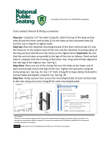
Service Clearances
Figure 2. Service clearances
A
B
C
D
E
A
Electric
heat
VFD
Control box
and fan
Coil
Mixing Box/Filter
Filter
Table 1. Service clearance dimensions (inches)
Letter Component
Unit Size
3 6 8 10 12 14 17 21 25 30
A Filter 40.00 44.00 42.00 42.00 40.00 45.00 45.00 45.00 51.00 51.00
B Coil 49.00 62.00 66.00 78.00 86.00 86.00 94.00 94.00 96.00 109.00
C Control Box/Fan 56.00 56.00 56.00 56.00 56.00 56.00 56.00 56.00 56.00 56.00
D VFD 48.00 48.00 48.00 48.00 48.00 48.00 48.00 48.00 48.00 48.00
E Electric Heat 45.00 40.00 39.00 35.00 31.00 32.00 27.00 30.00 28.00 23.00
Notes: At a minimum, the above clearance dimensions are recommended on one side of the unit for regular service and maintenance. Clearance on both
sides is recommended.
Refer to as-built submittal for locations of items such as filter access doors, coil, piping connections, motor locations, etc.
Sufficient clearance must be provided on all sides of unit for removal of access panels, plug panels, or section-to-section attachment brackets.
Clearance for starters, VFDs, or other high-voltage devices must be provided per NEC requirements.

Dimensions and Weights
CLCH-SVX009A-EN 15
Table 2. Performance air handler model UCCA data
Nom airflow (CFM)
1500 3000 4000 5000 6000 7000 3500 10,500 12,500 15,000
Unit size 3 6 8 10 12 14 17 21 25 30
Horz unit height (in.) 27.50 32.50 38.00 38.00 41.80 45.60 48.10 54.30 60.60 60.60
Horz unit width (in.) 34.00 47.00 51.00 63.00 71.00 71.00 79.00 79.00 81.00 94.00
Horz unit length (in.) 51.90 54.90 52.30 54.70 54.70 56.20 60.20 60.20 62.90 69.60
Vert unit height (in.) 51.40 61.30 65.10 69.90 80.10 83.80 92.90 99.20 n/a n/a
Vert unit width (in.) 34.00 47.00 51.00 63.00 71.00 71.00 79.00 79.00 n/a n/a
Vert unit length (in.) 34.10 37.10 29.40 32.10 36.10 36.10 42.10 42.100 n/a n/a
Coils
Hydronic/DX coils (galvanized and stainless steel casing)
Area (ft
2
) 2.80 5.60 7.60 9.90 12.30 14.30 16.30 20.40 24.00 28.50
Width (in.) 17.50 22.50 27.50 27.50 30.00 35.00 35.00 43.75 50.00 50.00
Length (in.) 23.00 36.00 40.00 52.00 59.00 59.00 67.00 67.00 69.00 82.00
Velocity (fpm) 537 533 524 504 488 488 522 516 522 527
Dry Weight (lb.)
- 1-row hydronic 2335435365758196114127
- 2-row hydronic 30 47 60 74 92 105 116 140 163 185
- 4-row hydronic 48 79 101 128 157 181 200 252 287 329
- 4-row DX 41 73 95 121 146 169 188 227 263 311
- 6-row hydronic 61 104 134 171 210 243 270 340 390 452
- 6-row DX 55 97 129 163 197 228 255 318 366 433
- 8-row hydronic 77 132 173 221 270 313 349 437 504 586
Wet Weight (lb.)
- 1-row hydronic 29 44 54 66 84 96 103 123 146 163
- 2-row hydronic 38 60 76 94 119 137 150 186 217 246
- 4-row hydronic 61 101 130 165 204 236 261 332 380 436
- 6-row hydronic 79 135 176 223 277 321 357 452 521 604
- 8-row hydronic 100 173 227 289 357 413 461 582 674 783
Steam coils
Area (ft
2
) 1.80 4.40 6.50 8.50 9.80 13.30 15.10 16.80 21.30 25.30
Width (in.) 12.00 18.00 24.00 24.00 24.00 33.00 33.00 36.00 45.00 45.00
Length (in.) 22.00 35.00 39.00 51.00 59.00 58.00 66.00 67.00 68.00 81.00
Velocity (FPM) 818 686 615 588 610 527 562 627 588 593
Weight (lb.) 31 54 75 86 93 122 132 156 239 266

Dimensions and Weights
16 CLCH-SVX009A-EN
Nom airflow (CFM)
1500 3000 4000 5000 6000 7000 3500 10500 12500 15000
Unit size 3 6 8 10 12 14 7 21 25 30
Fan/Motor data
FC fans
Wheel size (in.) 9x7 12x9 12x12 15x15 18x15 18x18 20x15 20x20 20x18 22x20
Maximum RPM 2000 1500 1700 1400 1200 1200 1100 1000 1300 1150
Motor HP 1-2 1-3 1-5 1 - 5 1 - 7 1/2 1 - 7 1/2 1 - 10 2 - 15 3 - 15 1 1/2 - 15
Minimum design CFM 1050 2100 2800 3500 4200 4900 5950 7350 8750 10500
DDP fans
Wheel size (in.) 11 14 16 18 18 20 20 2 x 18 2 x 20 2 x 20
Maximum RPM 3600 3600 3400 3025 3025 2720 2720 3025 2720 2720
Motor HP 1-2 1 1/2 - 5 2- 7 1/2 3 - 7 1/2 3 - 10 3 - 15 3 - 15 3- 10 3- 10 5 - 15
Filters (height x width - inches) with quantity per size
2 in. and 2/4 in. combination flat filter
- 16 x 20 4 2 2 4 2
- 16 x 25 4 1 1 2 2 6
- 20 x 20 2 2 4 2
- 20 x 25 1 2 1 1 2 6 4
Area (ft
2
) 3.5 6.9 8.9 11.1 16.3 16.3 20.0 22.5 26.4 30.6
Nominal Velocity (fpm) 432.0 432.0 450.0 450.0 369.2 430.8 425.0 466.7 473.7 490.9
2-in. Angle Filter
- 16 x 20 2 6 6 6 4 12
- 16 x 25 2 3 3 8
- 20 x 20 4 2 4 6 8
- 20 x 25 2 12
Area (ft
2
) 5.6 11.1 12.5 15.6 21.7 21.7 30.0 31.1 41.7 48.9
Nominal Velocity (fpm) 270.0 270.0 320.0 321.4 276.9 323.1 283.3 337.5 300.0 306.8
Mix Box
Damper Area (ft
2
) 1.3 2.4 3.1 4.1 5.1 5.6 7.0 8.2 10.3 12.0
Nominal Velocity (fpm) 1166.9 1224.7 1288.5 1205.6 1178.0 1239.2 1217.0 1277.9 1208.1 1247.1
Notes: Hydronic coil weight based on 14 fins per inch. Steam coil weight based on 6 fins per inch.
Coil width = length in direction of coil header, typically vertical.
Coil length = length of coil in direction of the coil tubes, typically horizontal and perpendicular to airflow.
Unit sizes 21-30 have two stacked steam coils
Fan wheel size is diameter x length of blade (width).
Minimum airflow limit is for units with hot water, steam, or electric heat. There is no minimum airflow for cooling-only units.
Table 2. Performance air handler model UCCA data

Dimensions and Weights
CLCH-SVX009A-EN 17
Fans
Motors
Table 3. Fan weights (pounds) - no motor
Unit Size FC Fan DDP Fan
3 30.71 60.63
6 47.09 96.03
8 69.21 110.09
10 83.02 149.12
12 97.90 158.25
14 110.46 164.44
17 133.09 172.89
21 155.81 290.14
25 168.83 304.07
30 208.34 317.00
Note: Add motor weight to get total weight of fan.
Table 4. Motor weights (pounds)
Motor HP Voltage Motor Weight Frame Size
1 208, 230/460, 575 38 143
1.5 208, 230/460, 575 37 145
2 208, 230/460, 575 43 145
3 208, 230/460, 575 71 182
5 208, 230/460, 575 82 184
7.5 208, 230/460, 575 91 213
10 208, 230/460, 575 127 215
15 208, 230/460, 575 217 254

Dimensions and Weights
18 CLCH-SVX009A-EN
Table 5. VFD Weights (pounds) and Line Input
HP Type FLA RPM
VFD (single Fan) VFD (dual Fan)
Line Input Weight Line Input Weight
1
208 V / 60 Hz / 3 PH 3.50 1800 4.20 10
230 V / 60 Hz / 3 PH 3.00 1800 4.20 10
460 V / 60 Hz / 3 PH 1.50 1800 2.10 10
575 V / 60 Hz / 3 PH 1.20 1800 3.90 20
1.5
208 V / 60 Hz / 3 PH 5.10 1800 6.80 10
230 V / 60 Hz / 3 PH 4.40 1800 6.80 10
460 V / 60 Hz / 3 PH 2.20 1800 3.40 10
575 V / 60 Hz / 3 PH 1.80 1800 3.90 20
2
208 V / 60 Hz / 3 PH 6.50 1800 6.80 10
230 V / 60 Hz / 3 PH 5.80 1800 6.80 10
460 V / 60 Hz / 3 PH 2.90 1800 3.40 10
575 V / 60 Hz / 3 PH 2.40 1800 3.90 20
3
208 V / 60 Hz / 3 PH 9.70 1800 15.20 15 22.00 27
230 V / 60 Hz / 3 PH 8.60 1800 15.20 15 22.00 27
460 V / 60 Hz / 3 PH 4.20 1800 4.80 12 11.00 20
575 V / 60 Hz / 3 PH 3.30 1800 3.90 20 9.00 25
5
208 V / 60 Hz / 3 PH 15.70 1800 22.00 22 42.00 31
230 V / 60 Hz / 3 PH 13.60 1800 22.00 22 42.00 31
460 V / 60 Hz / 3 PH 6.70 1800 8.20 12 14.00 20
575 V / 60 Hz / 3 PH 5.30 1800 6.10 20 11.00 25
7.5
208 V / 60 Hz / 3 PH 22.40 1800 28.00 22 59.40 64
230 V / 60 Hz / 3 PH 19.40 1800 28.00 22 59.40 64
460 V / 60 Hz / 3 PH 9.40 1800 11.00 15 21.00 27
575 V / 60 Hz / 3 PH 7.60 1800 9.00 20 18.00 37
10
208 V / 60 Hz / 3 PH 29.50 1800 42.00 26 59.40 64
230 V / 60 Hz / 3 PH 25.20 1800 42.00 26 59.40 64
460 V / 60 Hz / 3 PH 12.50 1800 14.00 15 27.00 27
575 V / 60 Hz / 3 PH 10.00 1800 11.00 20 22.00 37
15
208 V / 60 Hz / 3 PH 43.40 1800 59.40 59
230 V / 60 Hz / 3 PH 37.80 1800 59.40 59
460 V / 60 Hz / 3 PH 18.50 1800 21.00 22 40.00 31
575 V / 60 Hz / 3 PH 14.80 1800 18.00 20 34.00 64

CLCH-SVX009A-EN 19
Installation - Mechanical
Lifting and Rigging
Remove Shipping Tie-Downs
Prior to unit placement, remove the shipping tie-downs.
See Figure 3 thru Figure 8.
Horizontal FC Fan 3-10
1. Remove screws attaching shipping protection brackets
from floor.
2. Remove shipping protection brackets through the
door.
Vertical FC Fan 3-10
1. Remove screws attaching shipping protection brackets
from center of isolation base to casing mounting
bracket.
2. Remove shipping protection brackets through door.
Figure 3. Shipping tie-down removal for horizontal FC
fan 3-10 - remove screws
Figure 4. Shipping tie-down removal for horizontal FC
fan 3-10 - remove bracket
Detail A
See Detail A
Figure 5. Shipping tie-down removal for vertical FC fan
3-10 - remove screws
Figure 6. Shipping tie-down removal for vertical FC
fan 3-10 - remove brackets
Detail A
See Detail A

Installation - Mechanical
20 CLCH-SVX009A-EN
FC Fan Size 12-30
1. Remove drive side screws on isolator brackets
2. Cut banding and remove
Direct-Drive Plenum Fans
1. Remove two screws on the motor side of the fan
assembly
General Lifting Considerations
Figure 7. Shipping tie-down removal for FC fan 12-30
Figure 8. Shipping tie-down removal for DDP fan
See Detail B
Detail B
See
Detail C
Detail C
WARNING
Risk of Unit Dropping!
Do not use skid tie down brackets to lift the unit.
Improper use of the tie down brackets could result in
unit dropping and crushing technicians which could
result in death or serious injury, and equipment
damage.
Figure 9. Do not use skid tie down for lifting
WARNING
Heavy Objects!
Failure to follow instructions below or properly lift unit
could result in unit dropping and possibly crushing
operator/technician which could result in death or
serious injury, and equipment or property-only damage.
Ensure that all the lifting equipment used is properly
rated for the weight of the unit being lifted. Each of the
slings used to lift the unit must be capable of
supporting the entire weight of the unit. Lifting slings
may not be of the same length. Adjust as necessary for
even unit lift.
WARNING
Risk of Unit Dropping!
Failure to follow instruction below could result in death
or serious injury. To prevent modules/subassemblies
from dropping, ALWAYS place, assemble, and suspend
them one at a time.
/