Page is loading ...

How to Assemble the Trapeze Table (Cadillac)
Not Shown: Velcro Ankle Cuffs, Velcro Thigh Cuff, Roll Down Bar, Vinyl Flap
ʐ
Canopy Top
ʐ
Top Slider
ʐ
Corner Connector
Ơ
Vertical
Tube
Assembly
(Push
Through
Bar end)
j
Push Through
Bar (PTB)
ʏ
Pull-Out
Shelf & Head
Box Cushion
(Optional)
ʏ
Fuzzies
Trapeze Bar
and Sling
j
Cotton
Loops
j
Leg
Springs
j
Vertical
Slider
j
Flange Connector
Ơ
Vertical
Tube
Assembly
(Slider Bar
end)
Ơ
Sliders
with Pull
Knobs
Contact Us
1-800-PILATES | +1-916-388-2838
pilates.com | info@pilates.com
400-345 | 07.02.18

IMPORTANT:
This manual is intended for medical and fitness professionals, or
persons with experience in the use of this equipment. If there is
a question regarding appropriateness of a particular movement,
please consult a licensed health professional.
Safety Note: Warning – The Trapeze Table contains flammable
materials, please keep away from direct heat.
INTRODUCTION
The Balanced Body Trapeze Table (Cadillac) consists of a padded
table surrounded by a frame made of metal poles. Eyebolts in
the frame provide attachment points for the springs. Loops,
handles or a wooden Roll-down Bar can be attached to the
springs creating a wide variety of exercises. The Trapeze Table
has two moving cross bars or sliders: one between the uprights
on one end of the table (vertical slider), and the other between
the overhead bars (horizontal slider). The head end of the Trapeze
Table holds a hinged wooden or aluminum frame called the
Push-through Bar (PTB).
Please see the attached diagram for a listing of the various parts
of the Trapeze Table.
FEATURES OF THE
TRAPEZE TABLE (CADILLAC)
1. SPRING ATTACHMENT POINTS
Low: Springs are attached from eyebolts in the wood frame at
the PTB end of the table. These springs are used for bottom
sprung exercises using the PTB.
Middle: Springs are attached to the vertical slider.
High: Springs are attached to eyebolts in the upper corners of
the canopy.
Overhead: Springs are attached to the horizontal slider between
the overhead bars.
2. TRAPEZE TABLE SPRINGS
The Trapeze Table has the widest variety of springs and the
greatest number of possible attachment points of any Pilates
equipment. Suggested spring weights and attachment points are
included for each exercise.
3. SPRING CODING
The Trapeze Table has two different lengths of springs – long
springs and short springs. Each length of spring comes in
different resistances. The standard Balanced Body spring coding
is as follows:
Short springs
» Yellow – Light
» Blue – Medium
» Red – Heavy
» Black – Very heavy, usually used on the Trapeze Bar
Long springs
» Yellow – Light
» Purple – Medium
4. SAFETY
It is very important that that the instructor is present and
spotting the client whenever the Push-through Bar is in use. The
Push-through Bar should never be adjusted low enough to hit a
client who is lying under it. The safety strap must always be used.
The safety strap must be adjusted so that the angle of the Push-
through Bar, when viewed from the side, is no lower than either
the four or eight o’clock position. There are three height positions
for the Push-through Bar pivot point. If a client is positioned
below the bar, raise the pivot point to avoid the client.
5. UPHOLSTERY CLEANING AND DISINFECTING.
You can extend the life of your upholstery by keeping it clean and
free of dirt, oil and perspiration. After each use, wipe down the
upholstery with a solution of mild soap and water. Then wipe it
down with clean water and dry with a rag.
2

PARTS LIST (INCLUDED):
DESCRIPTION PART NUMBER QT Y.
Ankle Velcro (pair) 101-001 1
Cotton Loop (pair) 101-005 1
Long Web (pair) 101-026 1
Thigh Velcro (pair) 101-020 1
Wool Fuzzy (pair) 101-022 1
Roll down bar 710-010 1
Belly Strap 210-034 1
Red Trapeze Spring SPR9001 2
Yellow Trapeze Spring SPR9002 2
Blue Trapeze Spring SPR9004 2
Long Yellow Trapeze Spring SPR9006 2
Long Purple Trapeze Spring SPR9461 2
Black Trapeze Spring (attached to
trapeze bar)
SPR9005 2
Safety Strap 210-058 1
Trapeze Bar w/Springs and Sling 950-059 1
Vertical Slider TRP6002 1
Horizontal Slider TRP6003 1
1/8" Cotter Pin 216-000 4
3/16" Allen Wrench GEN9280 1
Push Through Bar for Slider
Assembly
707-287 1
Push Through Bar Slider Assembly N/A 2
Push Through Bar Slider Shoulder
Bolt
619-202 2
Push Through Bar Slider 4th Side TRP0108 1
Button Head Screw with Pin End 619-200 2
21mm x 1/2" wrench ALL0060 1
7/32" Allen wrench TOL1358 1
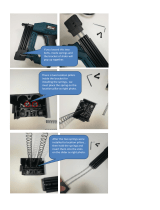
ASSEMBLE THE TRAPEZE CANOPY
1. Using the provided 3/16" allen wrench, loosen the set screws
in each of the eight flange connectors mounted to the
outside of the frame. Remove the two vertical tubes from the
box and the sliding push thru bar system. Lay the tubes down
so the holes on the sides of the tubes face away from each
other. Take the sliders of the Push Through Bar (PTB) and
slide them over the tubes opposite the end with the eye bolts,
you will need to pull the knobs of the sliders out to move the
sliders up the tubes. Continue to move the sliders up the
tubes until the pins lock into the bottom set of the three holes
in the tube. Make sure both sliders are locked into the same
bottom holes. Insert the provided cotter pins into each of
the 1/8” holes near the bottom ends of the tube. Pick up this
assembled tube set, be careful of the PTB, it may swing; place
the assembly in the flanges on the head end of the machine
(the end with the vinyl flaps). Be careful of the cotter pins so
they do not scratch the vinyl or wooden frame. The cotter pins
will automatically set the tubing height.
Insert the provided cotter pins into each of the 1/8” holes near
the bottom ends of the other two vertical tubes. Pick up the
tube assembly with the vertical slider and place the tube ends
into the flanges on the foot end of the frame.
2. Now set the canopy top onto the four vertical tubes. You will
need help with this. The end of the canopy frame with the
black safety strap goes over the push-through bar. Be certain
all four corner fittings fit securely over the tubes.
3. Using the 3/16" allen wrench, tighten the set screws in the
corner fittings and in the flanges around the frame. After
tightening all set screws in all the corner angles, test the
movement of the sliding push thru bar. To do this pull the
knobs of the sliders out and start sliding the PTB up or down.
This system should move easily and not stick when uniform
pressure is applied on each side. If the sliders stick when
moving the position, simply loosen the set screws that are
holding the vertical poles, rotate the tubes as necessary until
the sliders move freely. Be sure to re-tighten all set screws.
Remove the cotter pins from the tubes and save for future
use.
3

INSTALLING/REMOVING THE PUSH THROUGH BAR
(PTB) 4TH SIDE
Using the provided 7/32” allen wrench and button head screws
with pin ends, move the PTB to a 45 degree position. Line up
the 4th side opening with the threaded holes in the PTB. Thread
in one screw into the side of the PTB, the pin end of the screw
will go inside the 4th side. Repeat for the other side. Tighten
both screws with the allen wrench. Reverse these instructions to
remove the 4th side. Keep these button head screws if needed
later.
HOW TO ADJUST YOUR SLIDING PUSH THROUGH BAR
Position your hands on the outside of each slider. Place your
middle and/or ring fingers under the silver base of the knob; right
where the black body of the knob threads into. Place your index
finger and thumb around the knob itself. Pull each of the knobs
outwards, away from the vertical tubes, until they stop. Using the
same force on each arm, move the slider upwards or downwards
to each new location. Once you near a new location slightly
release the outward pull of the knobs. The pins will automatically
fall into the next position when aligned.
WEEKLY MAINTENANCE
Inspect springs for separations, and replace if needed. Inspect
snaps on springs and make sure the retractors operate smoothly.
Replace them if worn or do not operate freely. Make sure that
there are no indentations on the inside of the hooks.
Inspect all nuts, eyebolts and setscrews for tightness. Tighten or
replace if necessary.
It is recommended to check to ensure the pins in the plunger
knobs protrude and lock into the vertical tubes. First pull both
knobs out and start moving the sliders to a different position.
Release the knobs before the next hole and continue to slide the
system. Once over a hole the pin of the knob will drop into the
opening. Once each slider is in a new position apply a down force
on the PTB directly downwards. The pins of the sliders should
not come out of the holes. If the pins do not stay in the tube
holes, the pull knobs need to be replaced; call Balanced Body for
replacement parts.
WARNING: This machine is potentially dangerous, and Balanced
Body Inc. assumes no liability towards use or misuse. If you are
not fully aware of the safety issues and use of this machine, do
not use it. Use only with qualified instructor supervision.
QUESTIONS?
Call Balanced Body at 1-800-PILATES (1-800-745-2837) or
+1 916-388-2828.
ASSEMBLY PODCAST
You can also see the Trapeze Table assembly podcast located on
the Instructions & Safety page of our Web site, pilates.com.
Contact Us
1-800-PILATES | +1-916-388-2838
pilates.com | info@pilates.com
400-345 | 07.02.18
/