Zenith IQD61W20 Operating instructions
- Category
- LCD TVs
- Type
- Operating instructions

machine number IQD61W20
operating guide
table of contents
page
5
glossary of terms
page
67
Toll Free Digital TV Hotline: 1-8OO-243-0000
®
®

PAGE 2
206-3674
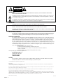
WARNING:
TO REDUCE THE RISK OF ELECTRIC SHOCK DO NOT REMOVE COVER (OR BACK). NO USER SERVICEABLE PARTS INSIDE.
REFER TO QUALIFIED SERVICE PERSONNEL.
The lightning flash with arrowhead symbol, within an equilateral triangle, is intended to alert the user to the presence
of uninsulated “dangerous voltage” within the product’s enclosure that may be of sufficient magnitude to constitute a
risk of electric shock to persons.
The exclamation point within an equilateral triangle is intended to alert the user to the presence of important operating
and maintenance (servicing) instructions in the literature accompanying the appliance.
WARNING:
TO PREVENT FIRE OR SHOCK HAZARDS, DO NOT EXPOSE THIS PRODUCT TO RAIN OR MOISTURE.
POWER CORD POLARIZATION:
CAUTION: TO PREVENT ELECTRIC SHOCK, MATCH WIDE BLADE OF PLUG TO WIDE SLOT, FULLY INSERT.
ATTENTION: POUR ÉVITER LES CHOCS ÉLECTRIQUES, INTRODUIRE LA LAME LA PLUS LARGE DE LA FICHE DANS LA BORNE
CORRESPONDANTE DE LA PRISE ET POUSSER JUSQU’AU FOND.
NOTE TO CABLE/TV INSTALLER:
This reminder is provided to call the cable TV system installer’s attention to Article 820-40 of the National Electric Code
(U.S.A.). The code provides guidelines for proper grounding and, in particular, specifies that the cable ground shall be
connected to the grounding system of the building, as close to the point of the cable entry as practical.
REGULATORY INFORMATION:
This equipment, trade name Zenith, model number, IQD61W20, has been tested and found to comply with the limits for
a Class B digital device, pursuant to Part 15 of the FCC Rules. These limits are designed to provide reasonable protection
against harmful interference when the equipment is operated in a residential installation. This equipment generates,
uses and can radiate radio frequency energy and, if not installed and used in accordance with the instruction manual,
may cause harmful interference to radio communications. However, there is no guarantee that interference will not occur
in a particular installation. If this equipment does cause harmful interference to radio or television reception, which can
be determined by turning the equipment off and on, the user is encouraged to try to correct the interference by one or
more of the following measures:
• Reorient or relocate the receiving antenna.
• Increase the separation between the equipment and receiver.
• Connect the equipment into an outlet on a circuit different from that to which the
receiver is connected.
• Consult the dealer or an experienced radio/TV technician for help.
The responsible party for this device compliance is:
Zenith Electronics Corporation
201 James Record Road
Huntsville, AL 35824, USA
Digital TV Hotline:
1-800-243-0000
CAUTION:
Do not attempt to modify this product in any way without written authorization from Zenith Electronics Corporation.
Unauthorized modification could void the user’s authority to operate this product.
2000 Zenith Electronics Corporation. All rights reserved.
WARNING
RISK OF ELECTRIC SHOCK
DO NOT OPEN
Dolby Digital®
Manufactured under license from Dolby Laboratories. “Dolby” and the double-D symbol are trademarks of Dolby Laboratories. Confidential Unpublished Works.
©1992-1997 Dolby Laboratories, Inc. All rights reserved.
The presence of the DTV certification mark indicates that this product will successfully receive digital television transmissions that conform to any and all of the
video formats described in the ATSC Digital Television Standard.
VCR Plus+, PlusCode and GUIDE Plus+ are trademarks of Gemstar Development Corporation. The VCR Plus+ and GUIDE Plus+ systems are manufactured under
license from Gemstar Development Corporation and VCR Index Systems B.V., respectively.
GEMSTAR IS NOT IN ANY WAY LIABLE FOR THE ACCURACY OF THE PROGRAM SCHEDULE INFORMATION PROVIDED BY THE GUIDE PLUS+ SYSTEM. IN NO EVENT SHALL
GEMSTAR BE LIABLE FOR ANY AMOUNTS REPRESENTING LOSS OF PROFITS, LOSS OF BUSINESS, OR INDIRECT, SPECIAL, OR CONSEQUENTIAL DAMAGES IN CONNECTION
WITH THE PROVISION OR USE OF ANY INFORMATION, EQUIPMENT, OR SERVICES RELATING TO THE GUIDE PLUS+ SYSTEM.
VCR is required for recording.

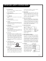
1. Read Instructions
Read all of the safety and operating instructions
before operating the product.
2. Retain Instructions
Keep all safety and operating instructions for next ref-
erence.
3. Heed Warnings
Follow warnings on the product and in the operating
guide.
4. Follow Instructions
Follow all operating and use instructions.
5. Cleaning
Unplug this product from the wall outlet before clean-
ing. Do NOT use liquid cleaners or aerosol cleaners! Use
a damp cloth for cleaning.
6. Attachments
Do not use attachments not recommended by product
manufacturer as they may cause hazards.
7. Water and Moisture
Do not use this product near water—for example, near
a bathtub, wash bowl, sink, or laundry tub, in a wet
basement, or near a swimming pool.
8. Accessories
Do not place this product on an unstable cart, stand,
tripod, bracket, or table. The product may fall, causing
serious injury to a child or adult, and serious damage
to the product. Use only with a cart, stand, tripod,
bracket, or table recommended by the manufacturer, or
sold with the product. Any mounting of the product
should follow the manufacturer’s instructions and
should use amounting accessory recommended by the
manufacturer.
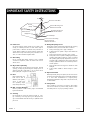
9. Transporting Product
Move product and cart combinations with care. Quick
stops, excessive force, and
uneven surfaces may cause
product and cart combina-
tion to overturn.
10. Ventilation
Slots and openings in the cabinet must not be blocked
or covered. They are provided for ventilation, to ensure
reliable operation, and to protect from overheating.
Never block openings by placing the product on a bed,
sofa, rug, or other similar surface. Do not place the
product in a built-in installation such as a bookcase or
rack unless proper ventilation is provided or manufac-
turer’s instructions have been adhered to.
11. Power Sources
Operate product only from the type of power source
indicated on marking label. If you are not sure of the
type of power supply to your home, consult your prod-
uct dealer or local power company. For products
intended to operate from battery power or other
sources, refer to the operating guide.
12. Power Cord Polarization
This product is equipped with a polarized alternating-
current line plug (a plug having one blade wider than
the other). This plug will fit into the power outlet only
one way. This is a safety feature. If you are unable to
insert the plug fully into the outlet, contact your elec-
trician to replace your obsolete outlet. Do not defeat
the safety purpose of the polarized plug.
13. Power-Cord Protection
Route power-supply cords so
they are not likely to be
walked on or pinched by
items placed upon or against
them, paying particular
attention to cords at plugs,
convenience receptacles, and
the point where they exit
from the product.
14. Outdoor Antenna Grounding
If an outside antenna or cable system is connected to
this product, be sure the antenna or cable system is
grounded so as to provide some protection against
voltage surges and built-up static charges. Article 810
of the National Electrical Code (USA), ANSI/NFPA 70,
provides information on grounding of the mast and
supporting structure, grounding of the lead-in wire to
an antenna discharge unit connection to the ground-
ing electrodes, and requirements for the grounding
electrode. (See Fig. 1 on reverse side for an example).
15. Lightning
For added protection for this
product during a lightning
storm, or when product is left
unattended and unused for
long periods of time, unplug
it from the wall outlet and
disconnect antenna or cable
system. This will prevent dam-
age to product due to light-
ning and power line surges.
PAGE 3
206-3674
IMPORTANT SAFETY INSTRUCTIONS
PORTABLE CART WARNING

16. Power Lines
An outside antenna system should not be located in the
vicinity of overhead power lines or other electric light or
power circuits, or where it can fall into such power lines or
circuits. When installing an outside antenna system, take
extreme care to keep from touching such power lines or cir-
cuits, as contact with them might be fatal.
17. Overloading
Do not overload wall outlets, extension cords or integral
convenience receptacles, as this can result in risk of fire or
electric shoc
k.
18. Object and Liquid Entry
Never push objects of any kind into this product through
openings, as they may touch dangerous voltage points or
shortout parts that could result in fire or electric shock.
Never spill liquid of any kind on the product.
19. Heat
Keep product away from
heat sources such as
radiators, heat registers,
stoves, or other prod-
ucts (including ampli-
fiers) that produce heat.
20. Wall or Ceiling Mounting
Mount a product to a wall or ceiling only as recommended
by the manufacturer.
21. Servicing
Do not attempt to service this product yourself, as open-
ing or removing covers may expose you to dangerous volt-
age or other hazards. Refer all servicing to qualified service
personnel.
22. Damage Requiring Service
Unplug this product from the wall outlet and refer servicing
to qualified service personnel under these conditions:
a. If the power-supply cord or plug is damaged.
b. If liquid has been spilled or objects have fallen into
the product.
c. If the product has been exposed to rain or water.
d. If the product doesn’t operate normally by following the
operating guide. Adjust only those controls covered by
the operating guide; improper adjustment of other con-
trols may result in damage and often requires extensive
work by a qualified technician to restore the product to
normal operation.
e. If the product has been dropped or cabinet has been
damaged.
f. If the product exhibits a distinct change in perfor-
mance.
23. Replacement Parts
When replacement part(s) are required, be sure service tech-
nician has used replacement part(s) specified by manufactur-
er or have same characteristics as original part(s).
Unauthorized substitutions may result in fire, electric shock,
or other hazards.
24. Safety Check
Upon completion of any service or repairs to this product,
ask service technician to perform safety checks to deter-
mine that product is in proper operating condition.
PAGE 4
206-3674
Antenna Lead-in Wire
Antenna Discharge Unit
NEC Section 810-20
Grounding Conductors
NEC Section 810-21
Ground Clamps
Power Service Grounding
Electrode System
NEC Art 250, Part H
Ground
Clamp
Electric Service
Equipment
IMPORTANT SAFETY INSTRUCTIONS

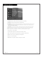
Table of Contents
PAGE 5
206-3674
Safety Warnings . . . . . . . . . . . . . . . . . . . . . . . . . . . .2
Important Safety Instructions . . . . . . . . . . . . . . . . . . .3
Hookup Directory . . . . . . . . . . . . . . . . . . . . . . . . . . .6
Step 1. Hook Up TV
Rear Jack Panel . . . . . . . . . . . . . . . . . . . . . . . . . . . .6
Front Jack Panel . . . . . . . . . . . . . . . . . . . . . . . . . . .7
ANT/CABLE Hookup . . . . . . . . . . . . . . . . . . . . . . . .8-9
CABLE BOX . . . . . . . . . . . . . . . . . . . . . . . . . . . .10-11
VCR + CABLE BOX . . . . . . . . . . . . . . . . . . . . . . . .12-13
DVD . . . . . . . . . . . . . . . . . . . . . . . . . . . . . . . . .14-15
HD SETTOP and PC . . . . . . . . . . . . . . . . . . . . . . .16-17
EZ LINK . . . . . . . . . . . . . . . . . . . . . . . . . . . . . . . .18
External Stereo Hookup . . . . . . . . . . . . . . . . . . . . . .19
Room Setups for Home Theater . . . . . . . . . . . . . . . . .20
Monitor Out . . . . . . . . . . . . . . . . . . . . . . . . . . . . . .21
Remote Button Functions . . . . . . . . . . . . . . . . . . .22-23
On-Screen Display . . . . . . . . . . . . . . . . . . . . . . . . . .24
Front Panel Controls . . . . . . . . . . . . . . . . . . . . . . . .25
Step 2. Customize your TV’s Features
Setup Menu
Main Source . . . . . . . . . . . . . . . . . . . . . . . . . . . . . 26
PIP Source . . . . . . . . . . . . . . . . . . . . . . . . . . . . . .27
EZ Scan . . . . . . . . . . . . . . . . . . . . . . . . . . . . . . . .28
Ch. Add/Del/Surf . . . . . . . . . . . . . . . . . . . . . . . . . .29
Ch. Label . . . . . . . . . . . . . . . . . . . . . . . . . . . . . . .30
Guide Plus+ . . . . . . . . . . . . . . . . . . . . . . . . . . .31~36
EZ Focus . . . . . . . . . . . . . . . . . . . . . . . . . . . . . . . .37
EZ Link . . . . . . . . . . . . . . . . . . . . . . . . . . . . . . . . .38
Video Menu . . . . . . . . . . . . . . . . . . . . . . . . . . . . .39
Audio Menu . . . . . . . . . . . . . . . . . . . . . . . . . . . . .40
Special Menu
Aspect Ratio . . . . . . . . . . . . . . . . . . . . . . . . . . . . .41
On-Screen Language . . . . . . . . . . . . . . . . . . . . . . . . 42
Captions/Text . . . . . . . . . . . . . . . . . . . . . . . . . . . .43
EZ Demo . . . . . . . . . . . . . . . . . . . . . . . . . . . . . . . .44
TIME Menu
Auto Clock . . . . . . . . . . . . . . . . . . . . . . . . . . . . . .45
Manual Clock . . . . . . . . . . . . . . . . . . . . . . . . . . . . .46
On Time . . . . . . . . . . . . . . . . . . . . . . . . . . . . . . . .47
Off Time . . . . . . . . . . . . . . . . . . . . . . . . . . . . . . . .48
Sleep Timer . . . . . . . . . . . . . . . . . . . . . . . . . . . . . .49
Lock Menu
Parental Lock . . . . . . . . . . . . . . . . . . . . . . . . . .50-51
QUICK Help . . . . . . . . . . . . . . . . . . . . . . . . . . . . . .52
EZ Help . . . . . . . . . . . . . . . . . . . . . . . . . . . . . . . .53
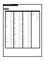
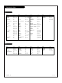
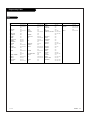
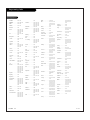
Programming the Remote . . . . . . . . . . . . . . . . . . . . .54
AUTO Search . . . . . . . . . . . . . . . . . . . . . . . . . . . . .55
Multi-Commands Memory Buttons . . . . . . . . . . . . . . . .56
TV and VCR “Punch-Through” Controls . . . . . . . . . . . . .57
Programming Codes . . . . . . . . . . . . . . . . . . . . . .58-62
Maintenance . . . . . . . . . . . . . . . . . . . . . . . . . . .63-64
Troubleshooting . . . . . . . . . . . . . . . . . . . . . . . . .65-66
Glossary . . . . . . . . . . . . . . . . . . . . . . . . . . . . . .67-68
Product Specifications . . . . . . . . . . . . . . . . . . . . . .69
Note: Design and specifications are subject to change without prior notice.

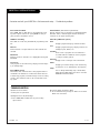
Mini glossary
JACK A connection on the back of a TV, VCR, or any other A/V device. This includes the RF jack and the Audio/Video jacks that are color-
coded.
SIGNAL Picture and sound traveling through cable, or on the air, to your television screen.
PAGE 6
206-3674
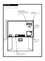
Rear Audio/Video Jacks
VIDEO 2
INPUT
VIDEO 1
INPUT
S-VIDEO
IN
MONITOR
OUT
Y
P
b
Pr
COMPONENT
ANT/CABLE2
INPUT
ANT/CABLE1
INPUT
R
L
R
L
R
L
S-VIDEO
OUT
CALIBRATION
RGB IN
S-VIDEO
IN
AUDIO
IN
Y
P
b
Pr
COMPONENT INPUT1
R
L
C
L
R
AUDIO
IN
VIDEOVIDEO
LOOP OUT
R
L
G-LINK
INPUT2
VARIABILE OUT
AUDIO
CENTER MODE
IN
MONO
MONO
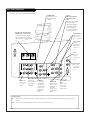
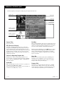
S-VIDEO In
A connection
available with
some high-end
equipment that
provides even
better picture
quality for
Video 1.
Variable Out
Used to connect
either an exter-
nal amplifier, or
add a sub-
woofer to your
surround sound
system.
RF Connectors: Antenna/Cable 1,
Antenna/Cable 2, and Loop Out
Used to connect analog cable or
antenna signals to the television,
either directly or through your cable
box.
Left/Right Audio
Used for stereo sound
from various types of
equipment.
Video 1 or 2
Connects the
video signals from
various types of
equipment.
Y, Pb, Pr
DVD Component Video
and HD Component
Video
Some top-of-the-line DVD
players use what is
called “component video,”
for extremely accurate
picture reproduction.
Refer to your DVD manual
for further information.
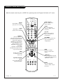
Connecting cables to your Entertainment Machine.
Monitor Out
Connects to a
second TV or
Monitor.
Left/Right Audio
Used for stereo
sound from various
types of equipment.
XGA and DBS
Input
Used to connect
from an XGA
source or DBS
Satellite system.
G-Link:
Used for con-
necting to
Gemstar equip-
ment.
PC Audio Input
Used in audio
connections for
VGA and DBS
input.
Center Mode IN
Connect to
external Dolby
Digital Center
“preamp out-
put.”

PAGE 7
206-3674
Front Audio/Video Jacks
Front A/V Panel
S-VIDEO
VIDEO
FRONT A/V
AUDIO
L/MONO R
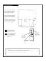
There are four jacks on the right side of
your Entertainment Machine that make
connecting Audio/Video devices like video
games and camcorders very simple.
The jacks are like those found in the jack
pack on the back of your Entertainment
Machine. This means that most equipment
that connects to those types of jacks in
the rear jack pack, can also be connected
in side.
To use the side jacks as the signal source,
use the Screen Source menu as described
on page 26. They will be named “Front
Video” in the Screen Source menu.
Left/Right Audio
Used for stereo sound
from various types of
equipment.
Video
Connects the video
signals from any
piece of equipment.
S-Video
A feature available
with some very
high-end equipment
that provides even
better picture quality.
When you choose Front Video
or Front S-Video, the audio is
automatically changed as well.
If you’re connecting a video game
unit, make sure to change the
picture settings with the Video
Preset option in the Video menu
(see page 39).
Mini glossary
A/V CABLES Audio/Video cables. Three cable connectors—Right audio (red), Left audio (white), and Video (yellow). A/V cables are used for stereo
playback of videocassettes and for higher quality picture and sound from other A/V devices.
A/V DEVICE Any device that produces video or sound (VCR, DVD, cable box, or television).

ANT / CABLE Hookup
PAGE 8
206-3674
RF coaxial wire
(75ohm)
Antenna
Signal Splitter
Cable TV
wall jack
RF coaxial wire
(75ohm)
ANT/CABLE2
INPUT
ANT/CABLE1
INPUT
LOOP OUT
VIDEO 2
INPUT
VIDEO
INPU
MONITOR
OUT
R
L
S-VIDEO
OUT
(MON (MONO)
VIDEO
1
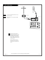
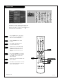
Connect the Entertainment Machine to your
antenna as shown.
Turn to page 28 to tune your ANT / CABLE
antenna.
For best performance, have your Antenna professionally adjusted.
2
If you receive your RF signal
through an antenna that is several
years old and connects with two
small prongs, you will need to pur-
chase a 300 to 75 Ohm adapter. It
should be available from your local
electronics dealer.
Zenith recommends using a 75
ohm cable for your antenna con-
nections in order to prevent inter-
ference.
VIDEO 2
INPUT
VIDEO 1
INPUT
S-VIDEO
IN
MONITOR
OUT
Y
P
b
Pr
COMPONENT
ANT/CABLE2
INPUT
ANT/CABLE1
INPUT
R
L
R
L
S-VIDEO
OUT
VIDEOVIDEO
LOOP OUT
INPUT2
MONO
MONO

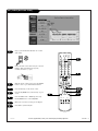
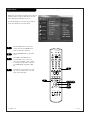
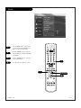
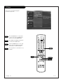
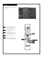
ANT / CABLE (On-Screen Guide)
PAGE 9
206-3674
For best performance, have your Antenna professionally adjusted.
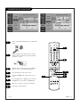
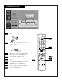
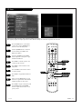
1
2
Plug in your Entertainment Machine into a 120V
60Hz outlet.
Remove the back of the remote and put in two AA
batteries. Make sure batteries are properly
installed (check the +/– signs).
With the remote control in hand, press the POWER
button to turn on your Entertainment Machine.
Press the HELP key on the remote control.
Using the UP/DOWN arrow, select Hook-up on your
screen.
Press the RIGHT arrow or ENTER key, then using
the UP/DOWN arrow to select ANT/CABLE.
Make your connections according to the diagram.
Press EXIT to quit the diagram.
3
4
5
6
7
back of
remote
1 2 3
4 5 6
7 8 9
0
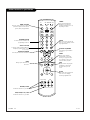
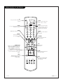
tv
mode
light
power
tv
video
front
comp1
xga
vcr
cable
dvd
sat
mute
vcr+ freeze flashbk
pip
menu
record stop
pause
rew
play ff
exit
guide
surf
info
vol
ch
pg up
ratio
pg dn
comp2
skip
source
enter
4
5/6
3
8
8
6
6

Antenna
Rf coaxial wire
(75ohm)
Cable box
In
Out
Cable TV
wall jack
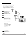
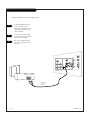
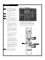
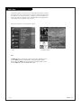
CABLE BOX
Locate the Antenna/Cable 2 jack on the
back of your TV. Connect the cable that
runs from the wall directly to the jack.
Now find the the Loop Out jack.
Connect the cable from this jack to the
Input jack on the back of your cable box.
Locate the Output jack on the back of
your cable box. Connect this to the
Antenna/Cable 1 jack on the back of your
TV.
To view the premium stations, set the
channel number on your cable box to
HBO, CINEMAX, SHOWTIME, etc. Then
press the TV button on your remote and
select the other Cable source (Ant/Cable
1).
To view the non premium channels press
the TV button and select Ant/Cable 2. Then
run EZ Scan to check for all available
channels and store them in memory.
This can be combined with any other
equipment you may want
to hook up. Hook cable directly into the
TV, then to the cable box. From there, the
cable box goes to the next device, down
the line, until the last piece, which con-
nects back to the TV in the
Antenna/Cable 1 jack.
1
2
3
4
Some cable services require the use of a cable box to decode pre-
mium channels and pay-per-view. Using the Loop Out to Decoder
option, and programming your remote, you can connect your cable
box so that you only need your MBR remote to control all the
channels. By connecting cable directly to your Entertainment
Machine, then running it out to the cable box and back, you make
the cable box another source to choose from in the Source selec-
tion on your remote.
To receive premium channels, run
Auto Program on the second source
that is set to receive channels.
PAGE 10
206-3674
VIDEO 2
INPUT
VIDEO 1
INPUT
S-VIDEO
IN
MONITOR
OUT
Y
P
b
Pr
COMPONENT
ANT/CABLE2
INPUT
ANT/CABLE1
INPUT
R
L
R
L
R
S-VIDEO
OUT
VIDEOVIDEO
LOOP OUT
INPUT2
MONO
MONO

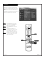
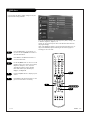
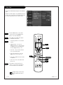
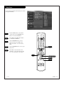
CABLE BOX (On-Screen Guide)
PAGE 11
206-3674
1 2 3
4 5 6
7 8 9
0
tv
mode
light
power
tv
video
front
comp1
xga
vcr
cable
dvd
sat
mute
vcr+ freeze flashbk
pip
menu
record stop
pause
rew
play ff
exit
guide
surf
info
vol
ch
pg up
ratio
pg dn
comp2
skip
source
enter
4
5/6
6
3
8
1
2
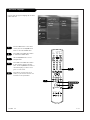
Plug in your Entertainment Machine into a 120V 60Hz
outlet.
Remove the back of the remote and put in two AA
batteries. Make sure batteries are properly installed
(check the +/– signs).
With the remote control in hand, press the POWER
button to turn on your Entertainment Machine.
Press the HELP button on the remote control.
Using the UP/DOWN arrow, select Hook-up on your
screen.
Press the RIGHT arrow or ENTER key, then Using the
UP/DOWN arrow to select CABLE BOX.
Make your connections according to the diagram.
Press EXIT to quit the diagram.
3
4
5
6
7
8
back of
remote
6

PAGE 12
In
Out
Audio
Video
3 4
VCR
Back AV panel
A/V cables
not included
with TV
Cable TV
wall jack
Round wire
(75ohm)
RF coaxial wire
(75ohm)
Antenna
S-Video
OR
DTV/RF
ANTENNA
INPUT
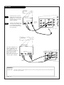
1
2
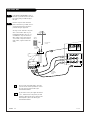
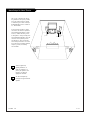
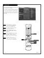
VCR+CABLE BOX
Locate the RF or VHF/UHF/CATV In jack on
the back of your VCR. Connect the cable
line coming from your wall directly to
this jack.
Find the composite video and audio
jacks on the back of your VCR, and con-
nect them following the instructions
provided with your equipment.
You may connect either the composite
video or the S-Video cables to your
Entertainment Machine. (Do not con-
nect BOTH the composite and the S-
Video cables. In the event that you
connect both composite and the S-
Video cables, only the S-Video will
work.)
To hear stereo sound from cable or your VCR,
you will need to connect A/V cables as well as
the wire that runs from the VCR to your
Entertainment Machine.
If you want to receive your signals on Channel
3 or 4, locate the Out to TV jack on your VCR.
Connect a cable from the Out to TV jack to the
Antenna/Cable 1 jack on the back of your
Entertainment Machine.
VIDEO 2
INPUT
VIDEO 1
INPUT
S-VIDEO
IN
MONITOR
OUT
ANT/CABLE2
INPUT
ANT/CABLE1
INPUT
R
L
R
L
S-VIDEO
OUT
VIDEOVIDEO
LOOP OUT
MONO
MONO
206-3674
LR

PAGE 13
206-3674
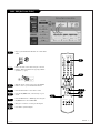
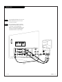
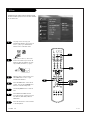
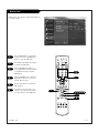
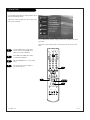
VCR+CABLE BOX (On-Screen Guide)
1 2 3
4 5 6
7 8 9
0
tv
mode
light
power
tv
video
front
comp1
xga
vcr
cable
dvd
sat
mute
vcr+ freeze flashbk
pip
menu
record stop
pause
rew
play ff
exit
guide
surf
info
vol
ch
pg up
ratio
pg dn
comp2
skip
source
enter
4
5/6
3
8
1
2
Plug in your Entertainment Machine into a 120V 60Hz
outlet.
Remove the back of the remote and put in two AA
batteries. Make sure batteries are properly installed
(check the +/– signs).
With the remote control in hand, press the POWER
button to turn on your Entertainment Machine.
Press the HELP key on the remote control.
Using the UP/DOWN arrow, select Hook-up on your
screen.
Press the RIGHT arrow or ENTER key, then Using the
UP/DOWN arrow to select VCR or VCR CABLE BOX.
Make your connections according to the diagrams.
Press EXIT to quit the diagram.
3
4
5
6
7
back of
remote
8
6
6

PAGE 14
Mini glossary
COMPONENT VIDEO Some video equipment uses three separate lines (Y, Pb, Pr) to more precisely reproduce images. Your manual will explain how
this relates to your equipment.
DVD Player
Find the audio and composite or
S-Video jacks on the back of your
DVD Player and connect them fol-
lowing the instructions provided
with your equipment.
You may connect either the com-
posite video or the S-Video cables
to your Entertainment Machine.
Do not connect both the compos-
ite and the S-Video.
1
2
Some high-end DVD players use
a picture reproduction system
called “component video.” If
your DVD player has component
output, use the connectors
marked “DVD” on the jack
panel. Please refer to your DVD
manual for proper installation.
Y
P
b
Pr
COMPONENT
R
L
RGB
S-VIDEO
IN
AUDIO
IN
Y
P
b
Pr
COMPONENT INPUT1
R
L
C
L
R
AUDIO
IN
R
L
INPUT2
VARIABILE OUT
AUDIO
CENTER MODE
IN
A/V cables
not included
with TV
Audio
LR
S-Video
DVD Player
Back AV panel
Dolby Digital
Out
R
L
Y
P
b
Pr
COMPONENT
R
L
S-VIDEO
IN
AUDIO
IN
Y
P
b
Pr
COMPONENT INPUT1
R
L
C
L
R
AUDIO
IN
INPUT2
VARIABILE OUT
AUDIO
CENTER MODE
IN
A/V cables
not included
with TV
Audio
LR
DVD Player
Back AV panel
Dolby Digital
Out
Component Video
206-3674

PAGE 15
206-3674
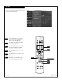
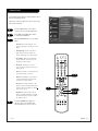
DVD Player (On-Screen Guide)
1 2 3
4 5 6
7 8 9
0
tv
mode
light
power
tv
video
front
comp1
xga
vcr
cable
dvd
sat
mute
vcr+ freeze flashbk
pip
menu
record stop
pause
rew
play ff
exit
guide
surf
info
vol
ch
pg up
ratio
pg dn
comp2
skip
source
enter
4
5/6
3
6
1
2
Plug in your Entertainment Machine into a 120V 60Hz
outlet.
Remove the back of the remote and put in two AA
batteries. Make sure batteries are properly installed
(check the +/– signs).
With the remote control in hand, press the POWER
button to turn on your Entertainment Machine.
Press the HELP button on the remote control.
Using the UP/DOWN arrow, select Hook-up on your
screen.
Press the RIGHT arrow or ENTER key, then Using the
UP/DOWN arrow to select DVD.
Make your connections according to the diagrams.
Press EXIT to quit the diagram.
3
4
5
6
7
8
back of
remote
8
6

Y
P
b
Pr
COMPONENT
R
L
RGB IN
S-VIDEO
IN
AUDIO
IN
Y
P
b
Pr
COMPONENT INPUT1
R
L
C
L
R
AUDIO
IN
R
L
G-LINK
INPUT2
VARIABILE OUT
AUDIO
CENTER MODE
IN
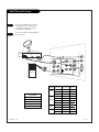
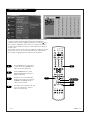
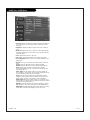
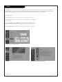
HD-SETTOP and PC Hookup
Find the audio and VGA jacks on the back
of your DBS receiver (or Computer) and
connect them following the instructions
provided with your equipment.
Connect these cables to your Entertainment
Machine as shown.
1
2
PAGE 16
206-3674
L
DBS Receiver
OR
Computer
Audio
L R
Dolby Digital
Out
VIDEO
HD-SETTOP
1080i
720P
480P
480i
240P
MODE Resolution Horizontal Vertical
640x480 31.5KHz 60Hz
640x480 37.9KHz 72Hz
640x480 37.5KHz 75Hz
800x600 35.2KHz 56Hz
800x600 37.9KHz 60Hz
800x600 48.1KHz 72Hz
800x600 46.9KHz 75Hz
1024x768 56.5KHz 70Hz
1024x768 60.2KHz 70Hz
640x350 31.5KHz 70Hz
240P
SVGA
VGA
XGA

PAGE 17
206-3674
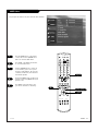
HD-SETT0P and PC Hookup (On-Screen Guide)
1 2 3
4 5 6
7 8 9
0
tv
mode
light
power
tv
video
front
comp1
xga
vcr
cable
dvd
sat
mute
vcr+ freeze flashbk
pip
menu
record stop
pause
rew
play ff
exit
guide
surf
info
vol
ch
pg up
ratio
pg dn
comp2
skip
source
enter
5/6
3
8
1
2
Plug in your Entertainment Machine into a 120V 60Hz
outlet.
Remove the back of the remote and put in two AA
batteries. Make sure batteries are properly installed
(check the +/– signs).
With the remote control in hand, press the POWER
button to turn on your Entertainment Machine.
Press the HELP key on the remote control.
Using the UP/DOWN arrow, select Hook-up on your
screen.
Press the RIGHT arrow or ENTER key, then Using the
UP/DOWN arrow to select HD-SETTOP or PC.
Make your connections according to the diagrams.
Press EXIT to quit the diagram.
3
4
5
6
7
8
back of
remote
6
6
4

PAGE 18
206-3674
EZ LINK (On-Screen Guide)
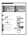
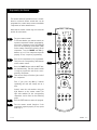
1
2
Plug in your Entertainment Machine into a 120V 60Hz
outlet.
Remove the back of the remote and put in two AA
batteries. Make sure batteries are properly installed
(check the +/– signs).
With the remote control in hand, press the POWER
button to turn on your Entertainment Machine.
Press the HELP key on the remote control.
Using the UP/DOWN arrow, select Hook-up on your
screen.
Press the RIGHT arrow or ENTER key, then Using the
UP/DOWN arrow to select HD-SETTOP or PC.
Make your connections according to the diagrams.
Press EXIT to quit the diagram.
3
4
5
6
7
8
1 2 3
4 5 6
7 8 9
0
tv
mode
light
power
tv
video
front
comp1
xga
vcr
cable
dvd
sat
mute
vcr+ freeze flashbk
pip
menu
record stop
pause
rew
play ff
exit
guide
surf
info
vol
ch
pg up
ratio
pg dn
comp2
skip
source
enter
5/6
3
8
6
back of
remote
6
4

Y
P
b
Pr
COMPONENT
R
L
RGB IN
S-VIDEO
IN
AUDIO
IN
Y
P
b
Pr
COMPONENT INPUT1
R
L
C
L
R
AUDIO
IN
R
L
G-LINK
INPUT2
VARIABILE OUT
AUDIO
CENTER MODE
IN
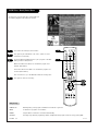
PAGE 19
206-3674
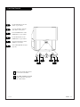
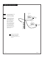
External Stereo
1
2
Locate the Variable Audio Out
jacks on the back of your
Entertainment Machine and the
Input jacks on the back of your
stereo's amplifier.
Connect the two jacks, making
sure that the right and left chan-
nels are placed correctly.
Set up your speakers through
your stereo, according to those
directions.
3
Hook up Left/Right Front Speaker to Amplifier System.
Analog stereo amplifier
Audio cables
not included
with TV
L R

PAGE 20
206-3674
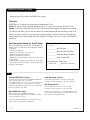
Room Setups for Home Theater
sub-woofer
right
speaker
left
speaker
surround
sound
speaker
surround
sound
speaker
This is just a general room design.
Any number of set-ups are possible,
and some changes may be needed
to maximize your sound. However, a
Dolby Digital Receiver is needed for
5.1 channel audio.
A left and right speaker on either
side of the set enhances separation.
The Entertainment Machine “center
mode in,” makes the dialog sound
as thought it’s coming directly from
the Entertainment Machine. The rear
surround sound speakers provide
the majority of other sounds, like
those from special effects in movies.
Your sub-woofer generates ultra-low
frequency sound, for rumbling
low-end audio.
Sound is affected by
speaker placement, so
make sure nothing is in
front of the speakers, and
that they are aimed in
appropriate directions.
You have the option of
turning on or off the internal
speakers.
Page is loading ...
Page is loading ...
Page is loading ...
Page is loading ...
Page is loading ...
Page is loading ...
Page is loading ...
Page is loading ...
Page is loading ...
Page is loading ...
Page is loading ...
Page is loading ...
Page is loading ...
Page is loading ...
Page is loading ...
Page is loading ...
Page is loading ...
Page is loading ...
Page is loading ...
Page is loading ...
Page is loading ...
Page is loading ...
Page is loading ...
Page is loading ...
Page is loading ...
Page is loading ...
Page is loading ...
Page is loading ...
Page is loading ...
Page is loading ...
Page is loading ...
Page is loading ...
Page is loading ...
Page is loading ...
Page is loading ...
Page is loading ...
Page is loading ...
Page is loading ...
Page is loading ...
Page is loading ...
Page is loading ...
Page is loading ...
Page is loading ...
Page is loading ...
Page is loading ...
Page is loading ...
Page is loading ...
Page is loading ...
Page is loading ...
Page is loading ...
Page is loading ...
Page is loading ...
-
 1
1
-
 2
2
-
 3
3
-
 4
4
-
 5
5
-
 6
6
-
 7
7
-
 8
8
-
 9
9
-
 10
10
-
 11
11
-
 12
12
-
 13
13
-
 14
14
-
 15
15
-
 16
16
-
 17
17
-
 18
18
-
 19
19
-
 20
20
-
 21
21
-
 22
22
-
 23
23
-
 24
24
-
 25
25
-
 26
26
-
 27
27
-
 28
28
-
 29
29
-
 30
30
-
 31
31
-
 32
32
-
 33
33
-
 34
34
-
 35
35
-
 36
36
-
 37
37
-
 38
38
-
 39
39
-
 40
40
-
 41
41
-
 42
42
-
 43
43
-
 44
44
-
 45
45
-
 46
46
-
 47
47
-
 48
48
-
 49
49
-
 50
50
-
 51
51
-
 52
52
-
 53
53
-
 54
54
-
 55
55
-
 56
56
-
 57
57
-
 58
58
-
 59
59
-
 60
60
-
 61
61
-
 62
62
-
 63
63
-
 64
64
-
 65
65
-
 66
66
-
 67
67
-
 68
68
-
 69
69
-
 70
70
-
 71
71
-
 72
72


Zenith IQD61W20 Operating instructions
- Category
- LCD TVs
- Type
- Operating instructions
Ask a question and I''ll find the answer in the document
Finding information in a document is now easier with AI
Related papers
-
Zenith IQD61W20 Operating instructions
-
-
-
-
-
-
Zenith C32C41 Operating Manual & Warranty
-
-
-
Other documents
-
RCA VR704HF User manual
-
Panasonic CT 27SX32 User manual
-
-
Philips 27-COLOR TV W-PIP-REMOTE-DBX STEREO 27PS60S User manual
-
Citizen C27401 User manual
-
-
-
Contec RT-U49E User manual
-
Toshiba TP55H60 Owner's manual
-
JVC AV 60D501 User manual