Page is loading ...

Valid for serial no. 940-xxx-xxxx0449 165 160 2009-10-07
A2 Multitrac
A2TF J1/ A2TF J1 Twin/
A2TG J1/ A2TG J1 4WD
Instruction manual

-- 2 --
Rights reserved to alter specifications without notice.
ENGLISH 4..............................................

3

ENGLISH
-- 4 --
TOCe
1SAFETY 5...........................................................
2 INTRODUCTION 8...................................................
2.1 General 8..................................................................
2.2 Welding Method 8...........................................................
2.3 Definitions 8................................................................
2.4 Horizontal Welding 8.........................................................
2.5 Technical data 9............................................................
2.6 Main components A2TF J1/ A2TF J1 Twin (SAW) 10.............................
2.7 Main Components A2TG J1/ A2TG J1 4WD (MIG/MAG) 10........................
2.8 Description of Main Components 11............................................
3 INSTALLATION 12....................................................
3.1 General 12..................................................................
3.2 Mounting 12.................................................................
3.3 Adjusting the brake hub 12....................................................
3.4 Connections 13..............................................................
4 OPERATION 16.......................................................
4.1 General 16..................................................................
4.2 Loading the welding wire (A2TF J1/ A2TF J1 Twin, A2TG J1) 17...................
4.3 Loading the welding wire (A2TG J1 4WD) 18.....................................
4.4 Changing the feed roller (A2TF J1/A2TF J1 Twin, A2TG J1) 19.....................
4.5 Changing the feed rollers (A2TG J1 4WD) 19....................................
4.6 Contact equipment for Submerged arc welding 20................................
4.7 Contact equipment for MIG/MAG welding 21.....................................
4.8 Refilling with flux powder (Submerged arc welding) 22.............................
4.9 Transportation of the Automatic Welding Machine 23..............................
4.10 Conversion of A2TF J1/ A2TF J1 Twin (Submerged-arc) to MIG/MAG welding 23.....
4.11 Conversion of A2TF J1 (submerged-arc welding) to Twin-arc 23....................
5 MAINTENANCE 24....................................................
5.1 General 24..................................................................
5.2 Daily 24.....................................................................
5.3 Periodic 24..................................................................
6 TROUBLESHOOTING 25..............................................
6.1 General 25..................................................................
6.2 POSSIBLE FAULTS 25.......................................................
7 ORDERING OF SPARE PARTS 25......................................
DIMENSION DRAWING 26................................................
SPARE PARTS LIST 29..................................................

-5-
SafeArcT GB
1SAFETY
Users of ESAB welding equipment have the ultimate responsibility for ensuring that
anyone who works on or near the equipment observes all the relevant safety precau-
tions. Safety precautions must meet the requirements that apply to this type of weld-
ing equipment. The following recommendations should be observed in addition to
the standard regulations that apply to the workplace.
All work m ust be carried out by trained personnel well-acquainted with the operation
of the welding equipment. Incorrect operation of the equipment may lead to hazar-
dous situations which can result in injury to the operator and damage to the equip-
ment.
1. Anyone who uses the welding equipment m u st be familiar with:
S its operation
S location of emergency stops
S its function
S relevant safety precautions
S welding
2. The operator must ensure that:
S no unauthorised person is stationed within the working area of the
equipment when it is started up.
S no-one is unprotected when the arc is struck
S the working area/working range is free from objects.
3. The workplace must:
S be suitable for the purpose
S be free from draughts
4. Personal safety equipment
S Always wear recommended personal safety equipment, such as safety
glasses, flame-proof clothing, safety gloves. Note! Do not use safety gloves
when replacing wire.
S Do not wear loose-fitting items, such as scarves, bracelets, r ings, etc., which
could become trapped or cause burns.
5. Protection against other risks
S Dust particles of a certain size can be harmful to man.
A ventilation system and extractor should therefor e be provided to eliminate
this risk.
S When replacing the wire drum, exercise the greatest caution as the end of
the wire could cause personal injury.
GB

-6-
SafeArcT GB
6. General precautions
S Make sure the return cable is connected securely.
S Work on high voltage equipment may only be carried out by a qualified
electrician.
S Appropriate fire extinquishing equipment must be clearly marked and close
at hand.
S Lubrication and maintenance must not be carried out on the equipment
during operation.
Mind the following:
S That the freewheel clutch of the gear shall be in locked position.
S That, if the operator leaves the machine, it shall be parked with blocks in
front of the wheels, in order to prevent the machine from moving
unintentionally.
S Make sure that the automatic welding m achine is not unstable before start.
S That the placement of the welding head and the wire reel influence the
centre of gravity of the machine.
Too high a centre of gravity means an unstable welding machine.
S That the consumption of wire and flux results in displacement of the weight
distribution during the welding.
WARNING, RISK OF CRUSHING!
Do not use safety gloves when replacing wire, feed rollers and wire bobbins.
GB

WARNING
ARC WELDING AND CUTTING CAN BE INJURIOUS TO YOURSELF AND
OTHERS. TAKE PRECAUTIONS WHEN WELDING. ASK FOR YOUR
EMPLOYER'S SAFETY PRACTICES WHICH SHOULD BE BASED ON MANU-
FACTURER'S HAZARD DATA.
ELECTRIC SHOCK - Can kill
S Install and earth the welding unit in accordance with applicable standards.
S Do not touch live electrical parts or electrodes with bare skin, wet gloves or wet
clothing.
S Insulate yourself from earth and the workpiece.
S Ensure your working stance is safe.
FUMES AND GASES - Can be dangerous to health
S Keep your head out of the fumes.
S Use ventilation, extraction at the arc, or both, to keep fumes and gases from
your breathing zone and the general area.
ARC RAYS - Can injure eyes and burn skin
S Protect your eyes and body. Use the correct welding screen and filter lens and
wear protective clothing.
S Protect bystanders with suitable screens or curtains.
FIRE HAZARD
S Sparks (spatter) can cause fire. Make sure therefore that there are no inflam-
mable m aterials nearby.
NOISE - Excessive no ise can damage hearing
S Protect your ears. Use ear defenders or other hearing protection.
S Warn bystanders of the risk.
MALFUNCTION
S Call for expert assistance in the event of malfunction.
PROTECT YOURSELF AND OTHERS!
READ AND UNDERSTAND THE INSTRUCTION MAN-
UAL BEFORE INSTALLING OR OPERATING.
-7-
SafeArcT GB
GB

-8-
hha1d1ea
2 INTRODUCTION
2.1 General
The A2TF J1/ A2TF J1 Twin automatic welding machine is designed for Submerged
Arc Welding of butt and fillet joints.
The A2TG J1/ A2TG J1 4WD automatic welding machines are designed for
MIG/MAG welding o f butt and fillet joints.
All other applications are prohibited.
They are intended for use in combination with PEK and ESAB's welding power
sources LAF or TAF.
2.2 Welding Method
2.2.1 Submerged Arc Weldin g (SAW)
For submerged arc welding the A2TF J1/ A2TF J1 Twin automatic welding machine
is always to be used.
S Submerged arc Light Duty.
Submerged arc light duty with a Ø 20 mm connector permits a load SAW to 800
A (100%).
This version can be equipped with feed rollers for single or twin wire welding
(twin-arc). A special knurled feed roller is available for flux-cored wire, which
guarantees even wire feed without the risk of deformation due to high feed pressure.
2.2.2 MIG/MAG Welding
For MIG/MAG welding use either automatic welding machine A2TG J1 or
A2TG J1 4WD (the A2TG J1 4WD consists of a four wheel drive wire feed unit).
In MIG/MAG welding the welding bead is shielded by way of shielding gas.
The welding head is water-cooled. T he cooling water is supplied by hoses from
connections intended for the purpose.
2.3 Definitions
SAW welding The weld bead is protected by a cover of flux during the welding.
SAW Light duty Permits welding with lower current load and thin wire.
MIG/MAG welding The weld bead is protected by shielding gas during welding.
Twin-arc welding Welding with two wires in one welding head.
2.4 Horizontal Weldin g
The automatic welding m achines are designed for horizontal welding.
They are not to be used for welding on inclined planes.
GB

-9-
hha1d1ea
2.5 Technical data
A2TF J1/
A2TF J1 Twin (SAW)
A2TG J1
(MIG/MAG)
Supply voltage 42 V AC 42 V AC
Permissible load at 100 %: 800 A 600 A
Wire dimensions:
solid single wire
cored wire
solid twin wire
1.6-4.0 mm
1.6-4.0 mm
2x1.2-2.0 mm
0.8-2.5 mm
1.2-3.2 mm
--
Wire feed speed, max 9m/min 16 m/min
Brake hub braking torque 1.5 Nm 1.5 Nm
T ravel speed 0.1-2.0 m/min 0.1-2.0 m/min
Turning radius for circumferential welding, min 1500 mm 1500 mm
Pipe diameter for internal joint welding, min 1100 mm 1100 mm
Max. weight of wire 30 kg 30 kg
Flux container volume
(Not to be filled with preheated flux)
6l --
Weight (excl. wire and flux) 47 kg 47 kg
Enclosure class IP10 IP10
EMC classification Class A Class A
A2TG J1 4WD (MIG/MAG)
Type of gas: Mix/Ar CO
2
Supply voltage 42 V AC 42 V AC
Permissible load at 100 %: 600 A 650 A
Wire dimensions:
Non--alloy / Low--alloy
Stainless steel
Cored wire
Aluminium
1.0--1.6 mm
1.0--1.6 mm
1.0--2.4 mm
1.0 -- 2.0 mm
1.0--1.6 mm
1.0--2.4 mm
Wire feed speed, max 25 m/min 25 m/min
Brake hub braking torque 1.5 Nm 1.5 Nm
T ravel speed 0.1-2.0 m/min 0.1-2.0 m/min
Turning radius for circumferential welding,
min
1500 mm 1500 mm
Pipe diameter for internal joint welding, min 1100 mm 1100 mm
Setting range, contact device ±45° ±45°
Max. weight of wire 30 kg 30 kg
Weight (wire excluded): 47 kg 47 kg
Enclosure class IP10 IP10
EMC classification Class A Class A
GB

-10-
hha1d1ea
2.6 Main components A2TF J1/ A2TF J1 Twin (SAW)
1. Carriage
2. Carrier
3. Wire feed unit
4. Slide kit, manual
5. Contact tube
6. Wire feed motor
7. Wire guide
8. Flux hopper
9. Flux tube
10. Guide pin
2.7 Main Components A2TG J1/ A2TG J1 4WD (MIG/MAG)
1. Carriage
2. Carrier
3. Wire feed unit
4. Slide kit, manual
5. Connector
6. Wire feed motor
7. Wire guide
See on page 11 for a description of the main components.
GB

-11-
hha1d1ea
2.8 Description of Main Components
2.8.1 Carriage
The carriage is provided with 4-wheel drive.
The carriage can be secured by way of the
locking lever (1).
2.8.2 Carrier
The control box, wire feed unit and flux hopper,
among other things, are to be fitted on the carrier.
2.8.3 Wire Feed Unit / Wire Feed Un it with fo ur-wheel Drive
The unit is used for guiding and feeding the welding wire down into the contact
tube/connector.
2.8.4 Manual Slides
The horizontal and vertical position of the welding head is adjusted by way of linear
slides. The angular motion can be freely adjusted using the rotary slide.
2.8.5 Contact Tube / Connector
Transfers welding current to the wire during welding.
2.8.6 Wire Feed Motor
The wire feed motor is used for feeding the welding wire.
2.8.7 Guide Pin
The guide pin is used to help positioning the welding head in the joint.
2.8.8 Flux Hopper / Flux Tube
The flux is filled into the flux hopper and is then transferred to the workpiece through
the flux tube.
The amount of flux to be dropped down is controlled by way of the flux valve fitted to
the flux hopper.
See “Refilling with flux on page 22.
2.8.9 Fine-wire straighten er
The unit is used for the straightening of fine wire.
GB

-12-
hha1i1ea
3 INSTALLATION
3.1 General
The installation must be executed by a professional.
WARNING
Rotating parts can cause injury, take great care.
3.2 Mounting
3.2.1 Wire drum ( Accessories)
Wire drum (1) is mounted on the brake hub (2).
WARNING
To prevent the reel sliding off the hub:
S
Lock the reel in place by turning the red knob as shown
on the warning label attached next to the hub.
3.3 Adjusting the brake hub
The brake hub is adjusted when delivered, if readjustment
is required, follow the instructions below. Adjust the brake
hub so that wire is slightly slack when wire feed stops.
S Adjusting the braking torque:
S Turn the red handle to the locked
position.
S Insert a screwdriver into the springs in the hub.
Turn the springs clockwise to reduce the braking torque
Turn the springs anticlockwise to increase the braking torque.
NB: Turn both springs through the same amount.
GB
-13-
hha1i1ea
3.4 Connections
3.4.1 General
S The PEK is to be connected by a qualified person. See instruction manual
0460 948 xxx, 0460 949 xxx, 0459 839 036.
S For the connection of welding power source LAF/ TAF, see separate instruction
manual.
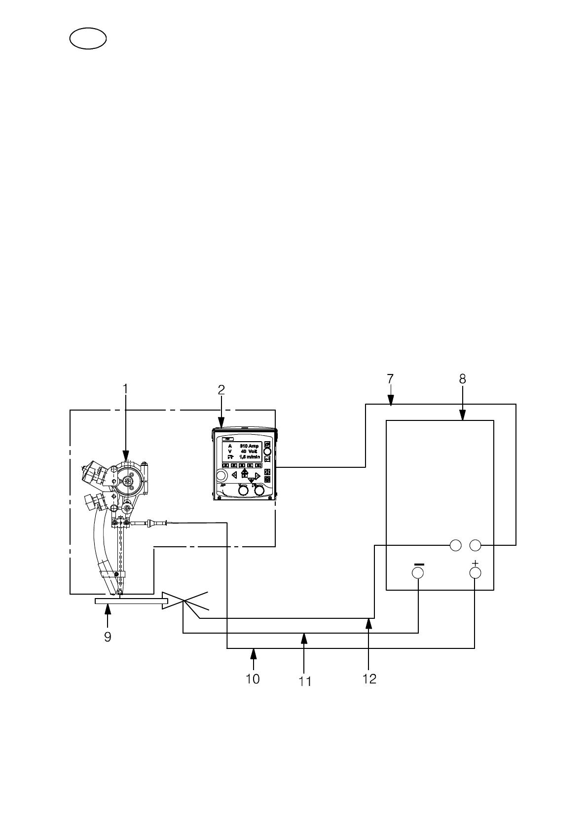
3.4.2 Automatic welding machine A2TF J1/ A2TF J1 Twin
(Submerged arc welding, SAW)
1. Connect the control cable (7) between the power source (8) and the control box
PEK (2).
2. Connect the return cable (11) between the power source (8) and work piece (9).
3. Connect the welding cable (10) between the power source (8) and the automatic
welding machine (1).
4. Connect the measurement cable (12) between the power source (8) and
workpiece ( 9 ).
GB

-14-
hha1i1ea
3.4.3 Automatic welding machine A2TG J1
(Gas metal arc welding, MIG/MAG)
1. Connect the control cable (7) between the power source (8) and control box
PEK (2).
2. Connect the return cable (11) between the power source (8) and work piece (9).
3. Connect the welding cable (10) between the power source (8) and the automatic
welding machine (1).
4. Connect the gas hose ( 5) between the reducer valve (6) and the gas connection
(13) on the welding machine.
5. Connect the cooling water hoses (3) between the cooling unit (4)andthe
automatic welding machine (1).
6. Connect the measurement cable (12) between the power source (8) and
workpiece ( 9 ).
GB

-15-
hha1i1ea
3.4.4 Automatic welding machine A2TG J1 4WD
(Gas metal arc welding, MIG/MAG)
1. Connect the control cable (7) between the welding power source (8) and the
PEK (2).
2. Connect the return cable (11) between the welding power source (8) and the
work piece (9).
3. Connect the welding cable (10) between the welding power source (8) and the
automatic welding machine (1).
4. Connect the gas hose ( 5) between the reduction valve (6) and the gas valve on
the automatic welding m achine (13).
5. Connect the hoses for cooling water (3) between the cooling unit (4) and the
automatic welding machine (1).
6. Connect the measuring cable (12) between the welding power source (8) and
the work piece (9).
GB

-16-
hha1o1ea
4OPERATION
4.1 General
WARNING:
Have you read and understood the safety
information ?
You must not operate the machine before then !
General safety regulations for the handling of the equipment can be found on
page 5. Read through before you start using the equipment!
Before welding start, check that the return cable is connected. See page 13- 15.
GB

-17-
hha1o1ea
4.2 Loading the welding wire (A2TF J1/ A2TF J1 Twin, A2TG J1)
A2TF J1 (SAW) A2TF J1 Twin (SAW) A2TG J1 (MIG/MAG)
1. Mount the wire drum according to the instructions on page 12.
2. Check that feed roller (1) and contact jaw or contact tip (3) are of the correct
dimension for the selected wire size.
3. For A2TF J1 Twin and A2TG J1:
S Feed the wire through the wire guide ( 8).
4. When welding with fine wire:
S Feed the wire through the fine Wire feed unit ( 6).
Ensure that the straightener is correctly adjusted so that the wire emerges
straight out through the contact jaws or contact tip (3).
5. Pull the end of the wire through the straightener (2).
S For a wire diameter greater than 2 mm; straighten out 0.5 m of wire and feed
it by hand down through the straightener.
6. Locate the end of the wire in the feed roller (1) groove.
7. Set the wire tension on the feed roller with the knob (4).
S Note! Do not tension more than is required to achieve an even feed.
8. Feed the wire forward 30 mm below the contact tip by pressing on the
control box PEK.
9. Direct the wire by adjusting the knob (5).
S Always use a guide tube (7) to ensure even feed of fine wire (1.6 - 2.5 mm).
S For MIG/MAG welding with wire sizes < 1.6 mm, use a guide spiral, which is
inserted in the guide tube (7).
GB

-18-
hha1o1ea
4.3 Loading the welding wire (A2TG J1 4WD)
1. Check that the feed rollers (1, 4) and the contact nozzle (7) are of the correct
dimension for the wire size selected.
NOTE!
The feed rollers are m arked with their respective groove diameter (D) on the
opposite side of the roller.
2. Undo the pressure devices (10) and put up the pressure arms (11).
3. Put the end of the wire through the wire guide nipple (12).
4. Locate the end of the wire in the groove of the feed roller (1) and feed it through
the intermediate nozzle (3).
5. Locate the end of the wire in the groove of the other feed roller (4) and feed it
through the outlet nozzle (9).
6. Put down the pressure arms (11) and adjust the wire tension on the
feed rollers (1, 4) by way of the pressure devices (10).
NOTE! Do not tighten down too hard.
7. Feed the wire forward 30 mm below the contact nozzle by pressing on
the control box PEK.
GB

-19-
hha1o1ea
4.4 Changing the feed roller (A2TF J1/A2TF J1 Twin, A2TG J1)
Single wire
S Release the knobs (3) and (4).
S Release the hand wheel (2).
S Change the feed roller (1).
They are m arked with their respective wire sizes.
Twin wire ( T win-arc)
S Change the feed roller (1) with twin grooves in the same way as for single wire.
S NOTE! The pressure roller (5) must also be changed. A special curved pressure
roller for twin wire replaces the standard pressure roller for single wire.
S Assemble the pressure roller with special stub shaft
(order no. 0146 253 001).
Flux-cored wire for knurled rollers (Accessories)
S Change the feed roller (1) and pressure roller (5) as a pair for the wire size to be
used.
NOTE! A special stub shaft is required for the pressure roller
(order no. 0212 901 101).
S Tighten the pressure screw (4) with moderate pressure to ensure that the
flux-cored wire does not deform.
4.5 Changing the feed rollers (A2TG J1 4WD)
S Undo the pressure devices (10).
S Put up the pressure arms (11).
S Undo the mounting screws (2)ofthe
feed rollers.
S Replace the feed rollers ( 1, 4).
S Adjust the wire tension on the new feed rollers.
GB

-20-
hha1o1ea
4.6 Contact equipment for Submerged arc welding
4.6.1 For single wire 1.6 - 4.0 mm. Light duty (D20)
Use automatic welding machine A2TF J1 (SAW)
where the following are included:
S Wire feed unit (1),
S Connector D20 (2)
S Contact tip (3) (M12 thread).
Tighten the contact tip (3) with a key in order to
ensure that a good contact is achieved.
4.6.2 Fortwinwires2x1.2-2.0mm,LightTwin(D35)
Use automatic welding machine A2TF J1 Twin (SAW)
where the following are included:
S Wire feed unit (1),
S Connector Twin D35 ( 2 )
S Contact tip (3) (M6 thread).
S F ine-Wire feed unit (5)
S Guide tubes (4, 6).
Tighten the contact tip (3) with a key in order to
ensure that a good contact is achieved.
Accessories:
S F ine-wire straightener (5)tobefittedontopof
the clamp of the wire feed unit (1).
N.B. When mounting the fine-wire straightener,
remove the plate ( 7 ) if it's exists.
N.B. Theprotectionplate(8) shall not be removed
Adjustment of the wires for T win-arc welding :
S Position the wires in the joint so as to achieve optimal weld quality by rotating the
connector. The two wires can be rotated so that they are positioned one after the
other along the line of the joint, or in any position up to 90 across the joint, i.e.
one wire on each side of the joint.
GB
/


