Page is loading ...

CL940A, CL945A
Digital Temperature
Calibrator–Thermometer
TM
e-mail: [email protected]
For latest product manuals:
www.omegamanual.info
Shop online at
omega.com
SM
User’s Guide

Where Do I Find Everything I Need
for Process Measurement and Control?
OMEGA… Of Course!
Shop online at omega.com
SM
TEMPERATURE
MU
Thermocouple, RTD & Thermistor Probes, Connectors, Panels & Assemblies
MU
Wire: Thermocouple, RTD & Thermistor
MU
Calibrators & Ice Point References
MU
Recorders, Controllers & Process Monitors
MU
Infrared Pyrometers
PRESSURE, STRAIN AND FORCE
MU
Transducers & Strain Gages
MU
Load Cells & Pressure Gages
MU
Displacement Transducers
MU
Instrumentation & Accessories
FLOW/LEVEL
MU
Rotameters, Gas Mass Flowmeters & Flow Computers
MU
Air Velocity Indicators
MU
Turbine/Paddlewheel Systems
MU
Totalizers & Batch Controllers
pH/CONDUCTIVITY
MU
pH Electrodes, Testers & Accessories
MU
Benchtop/Laboratory Meters
MU
Controllers, Calibrators, Simulators & Pumps
MU
Industrial pH & Conductivity Equipment
DATA ACQUISITION
MU
Communications-Based Acquisition Systems
MU
Data Logging Systems
MU
Wireless Sensors, Transmitters, & Receivers
MU
Signal Conditioners
MU
Data Acquisition Software
HEATERS
MU
Heating Cable
MU
Cartridge & Strip Heaters
MU
Immersion & Band Heaters
MU
Flexible Heaters
MU
Laboratory Heaters
ENVIRONMENTAL
MONITORING AND CONTROL
MU
Metering & Control Instrumentation
MU
Refractometers
MU
Pumps & Tubing
MU
Air, Soil & Water Monitors
MU
Industrial Water & Wastewater Treatment
MU
pH, Conductivity & Dissolved Oxygen Instruments
M5725/0219CL940A Rev. A

Table of Contents
TABLE OF CONTENTS
1. Instrument Description ............................................................. 1-1
Specifications .................................................................... 1-1
OMEGA Family of Thermometers ........................................... 1-5
2. Preparation for Use .................................................................. 2-1
General Information ........................................................... 2-1
Feature Overview ............................................................... 2-1
Safety Notices and Information ............................................ 2-2
Unpacking and Inspection .................................................... 2-4
Battery Installation and Replacement .................................... 2-4
Initial Power ON ................................................................. 2-5
3. Operating Instructions .............................................................. 3-1
Keypad Functions ............................................................... 3-1
LCD Display ....................................................................... 3-2
Setup Menu ....................................................................... 3-4
View Modes and Statistics .................................................... 3-6
Auto-Power Off .................................................................. 3-7
Backlight and Backlight Timeout ........................................... 3-8
Operating Modes ................................................................ 3-8
Trend Indicators ................................................................. 3-9
Battery Indicator ................................................................ 3-9
Probe Offset ...................................................................... 3-9
Open Lead Detection Enable/Disable ................................... 3-11
Clear Function .................................................................. 3-11
Presets: Save, Recall and Erase .......................................... 3-12
Invalid Measurement Indications ........................................ 3-13
4. Service Information ................................................................ 4-14
Inspection and Cleaning .................................................... 4-14
Calibration ...................................................................... 4-14
Troubleshooting ............................................................... 4-19
Diagnostic Routines and Error Codes ................................... 4-20
Memory Sterilization ......................................................... 4-20
Statement of Calibration .................................................... 4-21
A. Required Equipment .................................................................. A-i
B. Expanded Instrument Uncertainties ............................................. B-i
C. Instrument Verification Data Sheet .............................................. C-i

Instrument Description
1-1
1. INSTRUMENT DESCRIPTION
Specifications
Source/Measure
Accuracy
±0.003% * [READING] ± 5µV 18° TO 28°C
1
R
ESOLUTION
0.01°C
UP TO
999.99°C
AND
0.1°C
≥
1000°C
R
ANGE
-15
M
V
TO
85
M
V
C
OLD
J
UNCTION
E
RROR
±0.15°C
DISPLAY
5-D
IGIT
A
UTO
-R
ESOLUTION
(0.1/0.01)
WITH
B
ACKLIGHT AND
FUNCTION
ANNUNCIATORS
A
CCURACY
1
OVER RANGE OF
18
TO
28°C
(64.4
TO
82.4°F) | CJC error included
Conformity
ITS-90
Types B,E,J,K,N,R,S,T
EN 60584-1 2013 Type C
ASTM E988 Table 3 Type D
ASTM E1751 5.1.1 Type G
DIN 43710
Types L and U
ASTM E1751 5.1.2
Type P
Temperature Ranges
°C Range
°C
K
-230°C - 1372°C
-382°F - 2502°F
-230 to -160
±1.2 to ±0.6
-160 to -90
±0.5 to ±0.4
-90 to 380
±0.3
380 to 665
±0.2
665 to 1372
±0.3
J
-200°C - 1200°C
-328°F – 2192°F
-200 to -160
±0.7 to ±0.5
-160 to -110
±0.4
-110 to 10
±0.3
10 to 1200
±0.2
T
-260°C – 400°C
-436°F – 752°F
-260 to -190
±2.6 to ±0.7
-190 to -120
±0.6 to ±0.5
-120 to -70
±0.4
-70 to 80
±0.3
80 to 400
±0.2
1
See Graphs in Appendix B for Expanded Uncertainties

Instrument Description
1-2
E
-240°C – 1000°C
-400°F – 1832°F
-240 to -150
±1.2 to ±0.4
-150 to -100
±0.4
-100 to 20
±0.3
20 to 1000
±0.2
B
2
310°C – 1820°C
590°F – 3308°F
310 to 595
±1.8 to ±1.0
595 to 830
±0.9
830 to 965
±0.7
965 to 1820
±0.6
N
2
-230°C – 1300°C
-382°F – 2372°F
-230 to -150
±1.6 to ±0.7
-150 to -50
±0.5
-50 to 215
±0.3
215 to 1300
±0.2
R
2
-15°C – 1768°C
5°F – 3214°F
-15 to 100
±1.2 to ±0.8
100 to 240
±0.7
240 to 495
±0.6
495 to 1768
±0.5
S
2
-20°C – 1768°C
-4°F – 3214°F
-20 to 75
±1.2 to ±0.9
75 to 150
±0.8
150 to 285
±0.7
285 to 1768
±0.6
G
2
100°C - 2315°C
212°F – 4199°F
100 to 240
±1.0 to ±0.6
240 to 310
±0.5
310 to 460
±0.4
460 to 2315
±0.3
C
2
0°C – 2315°C
32°F – 4199°F
0 to 60
±0.5
60 to 2200
±0.4
2200 to 2315 ±0.5
D
2
0°C – 2315°C
32°F – 4199°F
0 to 100
±0.6 to ±0.5
100 to 230
±0.4
230 to 2315 ±0.3
2
Thermocouple types B, N, R, S, C, D, G, P, L and U are model CL945A only.

Instrument Description
1-3
P
2
0°C to 1395°C
32°F to 2543°F
0 to 1395 ±0.3
L
2
J-DIN
-200°C - 900°C
-328°F – 1652°F
-200 to -90
±0.6 to ±0.4
-100 to -40
±0.4
-40 to 655
±0.3
655 to 665
±0.4
665 to 900
±0.3
U
2
T-DIN
-200°C – 600°C
-328°F – 1112°F
-200 to -75
±0.8 to ±0.5
-75 to 0
±0.4
-0 to 385
±0.3
385 to 600
±0.2
Connector Type
Two (2) Mini-TC Copper
Temperature Units
°C, °F, mV
Probe Zero Function
Resolution 0.1 °C/°F
Reading Rate
3/sec. for Readings and TREND indicators
Battery Type
3 AA (IEC LR6, ANSI 15) Alkaline
Battery Life
500 Hours Typical
Battery Indicator
Four (4) Stage Battery Charge Indicator
Display
Two (2) rows of Five (5) digit LCD with separate minus
sign, decimal indicators, with offset, thermocouple types
KJTEBNRSGCDPLU, battery, source, read, temperature
units, voltage units, percent, trend, PRST (0-19), MIN,
MAX, AVG, RNG, STDEV, Transfer, symbols: Fast Ramp,
Slow Ramp, Step, Bluetooth
Statistics
Minimum Reading, Maximum Reading, Average Reading,
Reading Range, Standard Deviation
Display Backlight
Four (4) LED Backlight with 30-second timeout
Display Resolution
0.01° <1000 °
.1° ≥ 1000 °
Auto Off
20 minute no key pressed Auto Off. Feature can be
disabled
Keypad
Twelve (12) momentary switches with audible and tactile
feedback
Power Cycle
Configuration
Retention
Instrument retains: Sensor Type, Temperature Unit
Offset Values, Presets, Statistics, Open Lead detection
status, 0%/100% span settings, and operating mode
Internal Preset Storage
20 Preset user-determined storage registers, 0-19

Instrument Description
1-4
Input Current
±50 nA maximum
Maximum Common
Mode Voltage
42 V peak to earth 1 V p-p between T1 and T2
Low Resistance Load
Less than 5µV change in output with a 100KΩ resistance
Operating
Environment
Operating Temp
-20 to 55 °C
-4 to 131 °F
Storage Temp
-51 to 71 °C
-59.8 to 159.8 °F
Humidity
<10 °C (50 °F): Non-condensing
10 to 30 °C (50 to 86 °F): 5 to 95% RH
30 to 40 °C (86 to 104 °F): 5 to 85% RH
40°C to 55°C (104 to 131 °F): 5 to 60% RH
Altitude
0 to 4600 m
0 to 15,092 ft
Vibration
Random 10 – 500 Hz, 0.03 g
2
/Hz
Shock
30g Half Sine
Drop
4 Drops from 1 m to Concrete
Compliance, Electrical
CE, MIL-PRF-28800F Class 2
Compliance,
Substances
RoHS 2 Directive, 2011/65/EU Compliant, REACH
Electrical Safety
IEC-61010
EMC
EN 61326, MIL-PRF-28800F, Class 2
ESD
IEC 61326 Criterion B
Sanitation
NSF/ANSI/3-1 14159-2
Standards
MIL-PRF-28800F, Class 2
Temperature
Coefficient
For specification variances due to ambient operating temperature,
see the Expanded Instrument Uncertainty charts in Appendix B of
this manual. For ambient operating temperatures not shown in
Appendix B, accuracies shall be interpolated linearly.
Included Accessories
3 AA Batteries, Quick Start Guide, Tilt Stand/Magnetic,
Calibration Report
P
HYSICAL
CHARACTERISTICS:
Dimensions
193 x 84 x 28 mm
7.6 x 3.3 x 1.1 in
Weight including
Batteries
362.9g 12.8 oz.

Instrument Description
1-5
OMEGA Family of Thermometers
Thermocouple
Thermometers
HH911T
Thermocouple Thermometer, Single Input
HH912T
Thermocouple Thermometer, Dual Input
Data
Thermometers
HH931T
Data Thermometer, Single Input
HH932T
Data Thermometer, Dual Input

Preparation for Use
2-1
2. PREPARATION FOR USE
General Information
This manual provides operating instructions and maintenance information for two calibrator
instruments, CL940A and CL945A. These instruments are high performance calibrator-
thermometers capable of simulating and measuring a wide-variety of sensors. In addition,
features such as high accuracies, preset storage, ramp, step and transfer modes further
enhance their versatility.
It is recommended that you read this manual thoroughly, especially the sections on safety,
prior to operating these instruments.
Feature Overview
• 0.01° / 0.1 ° display resolution
• Internal storage for 20 presets
• 500-hour battery life
3
• Five (5) digit dual LCD with LED Backlight
• Simultaneous Source/Measure
• Comprehensive real-time statistics: MIN, MAX, AVG, RNG, and STDEV
• Easy to clean
• Probe offset function to minimize probe error
• °F, °C, and mV temperature and voltage units
• Durable: Meets MIL-PRF-28800F, Class 2 requirements
• Tilt Stand/Magnet/Hanger
3
Typical battery life under normal use conditions in laboratory environment. Continuous or repeated use of
features such as the backlight or use or storage at high or low temperature extremes may reduce battery life.

Preparation for Use
2-2
Safety Notices and Information
Read this Operation Manual thoroughly before using the instrument to become familiar with its
operations and capabilities.
Visually inspect instrument before using. Do not use if unit appears damaged or with any part of the
case removed.
WARNING
MAINTENANCE INSTRUCTIONS WITHIN THIS MANUAL ARE FOR USE BY QUALIFIED SERVICE
PERSONNEL ONLY. DO NOT ATTEMPT TO SERVICE THIS UNIT UNLESS YOU ARE QUALIFIED TO DO
SO.
SHOCK HAZARD
Disconnect all temperature probes and turn the unit off before removing the battery cover.
Never connect thermocouple leads to any source where more than 42 Volts (peak) could exist
between the lead and ground. If it is necessary to make measurements of an object at elevated
electrical potential, the user is responsible for obtaining and properly using a probe that provides
adequate insulation between the surface with elevated potential and the thermocouple wiring.
Always disconnect probe leads before opening the battery door or the instrument housing.
Internal circuits can present a shock hazard if leads are connected to a source of elevated potential.
Do not use this instrument if the housing, probe wiring, probe, or probe handle are damaged
or distorted. Housings and wire insulation are part of the personnel protection system, and if damaged
could expose users to elevated potentials.
EXPLOSION HAZARD
Never use or store this product with batteries installed, or change batteries, in an
environment where explosive or flammable vapors or dust suspensions may exist. For
thermocouple thermometers suitable for use in explosive environments, see Error! Reference source
not found.’s 921A or 922A Intrinsically Safe Thermometers.
Do not attempt to recharge alkaline batteries.
Do not put batteries into bags designed to protect parts from electrostatic discharge (ESD).
These bags are specially designed with metal shielding which can short circuit a battery.
Do not expose batteries to extreme heat or fire. Observe all regional laws and regulations when
disposing batteries.
Never use this instrument or any temperature probe or sensor inside a microwave oven.
BURN HAZARD
Do not touch a temperature probe sheath that has been exposed to toxic substances or
extremely high or low temperatures.
Do not attempt to measure temperatures beyond the range of the temperature probe. Probe
damage or personal injury could result from exceeding a probe’s maximum temperature rating.
Safety Notices and Information continued on next page . . . .

Preparation for Use
2-3
CAUTION
RISK OF INCORRECT READING
Do not use when AC or DC voltages in excess of 1V exist between thermocouple channels (on
instruments with more than one channel). Excessive voltage could result in an incorrect reading,
or in more extreme cases, a blown fuse that will result in incorrect readings and need for repair.
RISK OF INSTRUMENT DAMAGE
Only replace batteries with size AA (IEC LR6, ANSI 15). Observe proper polarity when installing
batteries. Do not mix old and new batteries.
Do not apply voltages across thermocouple leads in excess of normal thermocouple voltage
for the selected range. Excessive input voltage could result in blown fuse, component damage, or
fire. Application of excessive voltage is not covered by the warranty.
Avoid making sharp bends in probe or sensor lead wires. Bending lead wires at sharp angles can
damage the wire and cause probe failure.
When using both thermometer inputs and a voltage differential exists between the two
measurement points, at least one probe should be electrically insulated. If not, a ground-loop
current can flow through the thermocouple leads causing measurement error or instrument damage.
Static discharge through a connected temperature probe may cause instrument damage. Use
care to avoid static discharge when handling the instrument or connected probes.

Preparation for Use
2-4
Unpacking and Inspection
Each instrument is electrically and mechanically inspected before shipment. Upon receiving
your new OMEGA Data Thermometer, unpack all items from the shipping container and
check for any obvious damage that may have occurred during transit. Use the original
packing materials if reshipment is necessary.
If any dents, broken, or loose parts are seen, do not use the equipment. Notify OMEGA
immediately.
Check that all items are present. If any items are missing, notify OMEGA immediately.
The following items are included with every new instrument:
• One (1) Calibrator Thermometer;
• One (1) Quick Start Guide;
• Calibration Report;
• Three (3) AA, 1.5 V batteries; and
• Optional accessories (if purchased).
Battery Installation and Replacement
Three (3) AA 1.5 V batteries are supplied with the instrument, but not installed. Read the
following battery replacement instructions before attempting to install or remove the
batteries.
CAUTION
Always turn the instrument off and disconnect any input connections before replacing
the batteries. Re-install the battery compartment cover before resuming use of the
instrument.
CAUTION
The battery compartment is sealed with a rubber gasket. Use care to not damage the
gasket when removing or installing the battery compartment cover.
CAUTION
Remove the batteries when storing the instrument for an extended period of time or
in a high temperature environment to prevent battery leakage and possible damage
to the instrument.
All measurement parameters may be reset to factory default if batteries are removed while
the instrument is powered on. Always turn the instrument off before changing batteries.
To install or replace batteries:
Required Tools: Phillips Head Screwdriver
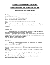
1. Identify the battery compartment located on the back of the instrument (see
Figure 1 below);
2. Remove the two (2) battery compartment retaining screws;
3. Remove the battery compartment cover;
4. If present, carefully remove old batteries being careful to not damage the battery
contacts;

Preparation for Use
2-5
5. Observing proper polarity, install three (3) new, AA alkaline (IEC LR6, ANSI 15)
batteries;
6. Re-install the battery cover and two (2) retaining screws;
7. At initial power on after battery replacement, allow approximately 30 seconds for
instrument to stabilize.
Figure 1: Battery Installation
Initial Power ON
OMEGA’s 900 Series Calibrator Thermometers are designed for easy operation, while still
providing a feature-rich experience via the intuitive user interface.
To get started follow these steps:
1. Perform Section 2.5, Battery Installation and Replacement;
2. The instrument will initially display every segment on the LCD for 2 seconds as a
test. An internal hardware, memory and battery self-test is performed during this
time.
3. Upon completing the internal tests, the instrument will immediately display the
Source and Read mode last user settings and battery indicator.
4. Set the desired measurement parameters as follows:
a. Enter the Setup Menu by pressing , hold the key down for
approximately 1.5 seconds, and then release it;
b. The active thermocouple type is flashing on the display. Use or
to select the desired thermocouple type. You are setting the
thermocouple type of the Read Channel.;
Retaining
Screws
Battery
Compartment
Gasket

Preparation for Use
2-6
The arrows always change a value. The arrows position
the cursor or will act to select only when changing Thermocouple type,
desired digit or changing the mode.
c. Momentarily (do not hold) press to save your selection and move to
the next parameter;
d. The active temperature unit is flashing on the display. Use to
select the desired temperature unit (°C, °F, or mV);
e. Momentarily press to save your selection and move to the next
parameter;
f. Read Channel 2 offset value is flashing on the display. If the
temperature probe’s offset value is known, press to set the
Channel 2 probe offset to the probe’s offset value. See Section 3.10,
Probe Offset, for more information.
g. Momentarily press to save your selection and move to Open Lead
Detection, press to toggle on/off;
h. Momentarily press to save your selection and move to Source on/off;
See Section 3.3, Set Up, figure 4 for more information.
i. To save the current parameter value and exit the Setup Menu, press ;
j. To disregard changes made to the current parameter value and exit the
Setup Menu, press .

Operating Instructions
3-1
3. OPERATING INSTRUCTIONS
Keypad Functions
The instrument keypad is a twelve (12) key, sealed membrane keypad. Each key provides
audible and tactile user feedback when pressed. Key functions are described in Figure 2
below.
Power instrument ON or OFF and exits Key
Lock mode.
(1.5s)
Disable auto-power OFF
(1.5s)
Enter instrument Setup Menu
While in Setup Menu, save current value and
step to next parameter
Toggle display backlight
(1.5s)
Disable backlight 30-second timeout
While in Setup Menu, discard all unsaved
changes and exit menu
(1.5s)
Delete all saved measurement data and
reset all statistics currently stored in
memory, MIN/MIX/AVG/RNG/STDEV
(1.5s)
While in PRST selection mode with PRST flashing, erases current preset
number contents
Displays in order: Current Source Channel reading, MIN, MAX, AVG, RNG,
STDEV
While in Setup Menu, save changes and exit menu
While displaying Cold Junction Compensation (CJC) reading, toggles between
CJC 1 and CJC 2
(1.5s)
Displays Cold Junction Compensation (CJC) readings.
The 10%/90% key toggles between 10% and 90% of span. The first press
of the key goes to 10%.
The 0%/+25% key manually increments the output by 25% of the defined
span for the selected TC. Once the output reaches 100% the next press of
the key will wrap around to 0%.
Once in Preset, single press saves and exits leaving the selected preset
number active
(1.5s)
Enters the Preset selection mode
Up and Down Buttons: Increment/Decrement currently selected Source digit
by 1.
Left and Right Buttons: Move active Source digit indicator by 1 place left or
right.
Figure 2 Keypad Button Functional Description
The , , , and keys have multiple functions which can be accessed by
momentarily pressing the key, or alternatively, by pressing and holding the key for

Operating Instructions
3-2
approximately 1.5 seconds. Throughout this Operation Manual, the press and hold sequence
is indicated by the key designator followed by the subscript (1.5s). For instance,
(1.5s)
indicates that the key should be pressed and held for 1.5 seconds, then released to
access the desired function.
LCD Display
The display is a large, easy to read, dual LCD display, with an LED backlight for clear
viewing in low-light conditions. It simultaneously displays Source channel and Read channel
values, current thermocouple type and temperature unit, Source and Read channel labels,
trend indicators for the Read Channel and a battery voltage indicator.
In Statistics View, the initial value displayed is a mirror of the Source channel. Each press
of the View key after that displays the active statistic result and its corresponding label
below. See Figure 3 below for further description of each display indicator.
1
OFFSET is
applicable to
Reading in
Line 2
2
Source
Channel 5
digit display
3
The active
thermocouple
type
4
Remaining
battery life
5
Temperature
units
6
Active Digit
Indicator
7
milliVolt
designation
8
Read
Channel 5
digit display
9 Value displayed in Read Channel display is a percentage
10
Value displayed in the Read Channel is the Standard Deviation (using total
population formula) over the last 1000 measurement cycles.
11
4
Flashing: Broadcasting to pair with a device
Solid On: Bluetooth connection has paired
12
Transfer is active. TRANSFER mode reads the input TC and outputs an offset
corrected mV signal to an upstream TC input. Source output is matched to the
reading using the same user settings.
4
Bluetooth symbol on LCD reserved for future models.

Operating Instructions
3-3
13 Range is currently displayed, the MAX minus MIN value.
14
Instrument is displaying the Average reading over the last 1000 measurement
cycles.
15
Step Function: There are 10 equal steps between 0°C and Span. Source
continuously steps up and down. There is a 5 second dwell time on each step.
16
MAX statistic. Displays the maximum reading over the last 1,000 measurement
cycles.
17
Slow Ramp: Source Channel continuously cycles from 0°C to Span and then back to
0°C. The ramp rate is 5°C per second.
18
MIN statistic. Displays the minimum reading over the last 1,000 measurement
cycles.
19
Fast Ramp: Source Channel continuously cycles from 0°C to Span and then back to
0°C. The ramp rate is 50°C per second.
20 Displays the number of the current 20 possible presets, (0-19).
21
PRST: Preset is active. Each preset value includes Source Value, TC Type, (no TC
type if in mV), Units, Mode, Span (0% and 100%), and preset number.
22 Trend Indicators, Read channel.
23 Minus sign, Read channel.
24 Read channel Label.
25 Minus sign, Source channel.
26 Source channel Label.
Figure 3: LCD Display Description
The LCD can display error information about the current measurement, as shown in Figure
4.
D
ISPLAY DESCRIPTION
OPEn No thermocouple probe is connected
O rnG
Over Range: The applied temperature is greater than the maximum
temperature for the selected thermocouple type
U rnG
Under Range: The applied temperature is less than the minimum
temperature for the selected thermocouple type
Figure 4: LCD Error Indications

Operating Instructions
3-4
Setup Menu
Key designators followed by (1.5s), e.g.
(1.5s)
, indicate that the key should be
pressed and held for 1.5 seconds, then released to access the desired function.
Measurement settings are configured in the Setup Menu. Press
(1.5s)
to access the Setup
Menu. From within the Setup Menu, press to step through the user-definable parameters
and the keys to increment/decrement or
keys to move left/right while in the
Setup Menu. The active parameter value will flash on the display or the active digit indicator
will flash beneath the digit.
Press to save a setting and exit the Setup Menu. Press to disregard unsaved changes
and exit the Setup Menu. If no key is pressed for 10 seconds, the current configuration is
saved and the instrument will exit the Setup Menu.
Figure 5 lists the user-definable parameters and the available values for each parameter.
To set a parameter value:
1. Press
(1.5s)
to enter the Setup Menu;
2. Press to cycle through parameters as shown in Figure 6 until the desired
parameter is reached;
3. To change the value of the current parameter, press
or ;
4. To save the current parameter value and cycle to the next parameter, press
(1.5s)
;
5. To save the current parameter value and exit the Setup Menu, press ;
6. To disregard changes made to the current parameter value and exit the Setup
Menu, press .
7. If parameter 2, “Temperature and Voltage Units” are set as either “°C” or “°F”, the
remaining parameter choices available are in Figure 5 below under “Setup Choices
for °C and °F”. If parameter 2 is set to “mV”, the remaining parameter choices
available are in Figure 5 below under “Setup Choices for mV”.
STATS
are not active in mV mode.

Operating Instructions
3-5
5
The CL945A includes K,J,T,E,B,N,R,S,G,C,D,P,L,U
6
All though still selectable, TC type is not visible on LCD while mV is the active unit
SETUP MENU CHOICES FOR °C AND °F
PARAMETER AVAILABLE VALUES
Thermocouple Type
5
K, J, T, E
Temperature and
voltage Units
°C, °F, mV
Probe Offset ±0.1 ° increments
Open Lead detection
(old)
On / Off
Source (SourC) On / Off
If on – Set Span
Set 100% Level
Set 0% Level
If on – Set Mode
Manual
blinking
“__ __ __ __”
Fast Ramp
Slow Ramp
Step
Transfer
SETUP MENU CHOICES FOR MV
PARAMETER
AVAILABLE VALUES
Thermocouple Type
6
K, J, T, E
5
Temperature and
voltage Units
°C, °F, mV
Probe Offset
±0.1mV increments
Open Lead detection
(old)
On / Off
Source (SourC)
On / Off
If on – Set Span
Set 100% Level

Operating Instructions
3-6
If no key is pressed for 10 seconds, the instrument will save the current configuration
and exit the Setup Menu.
View Modes and Statistics
The instrument features multiple view modes including a variety of real-time statistics, all
available at the touch of a button. Figure 6 below describes each view mode.
Set 0% Level
Range (rAnGE)
Range Hi mV (default)
[-15mV to +85mV]
Range Lo mV
7
(mV flashing)
[-15mV to +35mV]
If on – Set Mode
Manual
blinking
“__ __ __ __”
Fast Ramp
Slow Ramp
Step
Transfer
7
Low range is for calibration verification only.
Figure 5
VIEW MODE
D
ISPLAY
INDICATOR
DESCRIPTION
Minimum MIN
Minimum temperature recorded during current
session
Maximum MAX
Maximum temperature recorded during current
session
Average AVG
Average of all temperatures recorded during
current session
Range RNG Maximum minus Minimum
Standard Deviation STDEV
Standard deviation of all temperatures recorded
during the current session
1
.
1
Standard Deviation is calculated using the population formula: =
�
∑
(−µ)
2
Figure 6: View Modes and Statistics
/