CFM-34-REBM
Modular Fast Ethernet Bridge
Indoor Unit Management System
Technical Description and Configuration
Guide
Software Version 3.12
SAF Tehnika A/S 2003

Modular Fast Ethernet Bridge Management System Technical Description and Configuration Guide
V. 3.12. 1.0 · © SAF Tehnika A/S 2003 2
Table of Contents
1 CFM-34-REBM Fast Ethernet Bridge Indoor Unit Overview....................... 3
2 Fast Ethernet Bridge IDU Appearance...................................................... 4
2.1 Labelling ............................................................................................. 7
3 Interface modules.................................................................................... 8
3.1 V.35 Interface Module........................................................................... 8
3.1.1 Configuring V.35 Module.................................................................. 8
3.1.2 V.35 Interface Module LEDs ............................................................. 9
3.2 E1 Interface Module ............................................................................10
3.2.1 Configuring E1 Interface Module ......................................................10
3.3 REB Interface Module ..........................................................................11
4 Management Interfaces ......................................................................... 12
4.1 Reading the LEDs................................................................................12
4.2 LCD/Keypad .......................................................................................12
4.2.1 “Status Display” Mode of the IDU LCD Management Interface ..............12
4.2.2 “Setup” Mode of the IDU LCD Management Interface ..........................14
4.2.3 Reset Functions.............................................................................15
4.3 RS-232 Serial Management Port............................................................16
4.4 Ethernet Management Port ...................................................................19
4.4.1 Web Interface ...............................................................................19
4.4.2 SNMP Interface .............................................................................22
4.4.3 Command Line Interface for Telnet/ASCII consoles.............................26
4.5 Alarm Interface Port ............................................................................33
4.6 Performing Loop-back Tests..................................................................34
4.6.1 Ethernet interface loop tests............................................................34
4.6.2 Base-band and Radio loop tests .......................................................35
4.6.3 Interface Module loop tests .............................................................37
4.7 DIP Switch Settings .............................................................................39
4.8 Configuring Management Service Channel ..............................................40
4.9 Algorithm of LCD Operation ..................................................................43
4.10 Replacing the Indoor Unit .....................................................................44
4.11 Updating Management Software............................................................44
4.12 Default Settings ..................................................................................45
5 Configuring Radio Parameters ............................................................... 46
5.1 Default ODU Settings...........................................................................46
5.2 Configuring Tx Frequency.....................................................................46
5.3 Configuring Tx Power...........................................................................47
5.4 RSSI Voltage-Rx Signal Level Relation....................................................47
6 Pinouts................................................................................................... 48
7 Mechanical Data..................................................................................... 51
8 Frequency Channel Arrangement ........................................................... 52
9 SAF Tehnika A/S Contacts...................................................................... 54
10 References........................................................................................... 55
10.1 Technical Description ...........................................................................55
10.2 Configuration Guides ...........................................................................55
10.3 Management Software Update Guide......................................................55

Modular Fast Ethernet Bridge Management System Technical Description and Configuration Guide
V. 3.12. 1.0 · © SAF Tehnika A/S 2003 3
1 CFM-34-REBM Fast Ethernet Bridge Indoor Unit
Overview
Proprietary notice
The specifications or information contained in this document are subject to change
without notice due to continuing introduction of design improvements. If there is any
conflict between this document and compliance statements, the latter will supersede
this document.
The following document is dedicated to the CFM series Modular Remote Fast Ethernet
Bridge Indoor Units, describing the built-in management system, configuration
functionality, hardware features, etc.
This document describes particularly the CFM-34-REBM modular bridge.
The CFM-34-REBM Fast Ethernet Bridge is part of SAF Tehnika’s CFM series digital
microwave radio product family and serves as Indoor Unit (IDU) providing:
- Means of interconnecting Outdoor Unit (ODU or Radio) and user equipment;
The CFM-8-REBM, the CFM-16-REBM and the CFM-34-REBM is intended
for use with the CFM-LM Radio.
- Local management functionality.
Current document covers versions 3.12 and above for the management controller
software of all modular Ethernet bridge models.
The Ethernet bridge (henceforth in some places referred as primary bridge) is built
on the High performance full remote Ethernet bridge chipset. The Bridge is fully
compatible with IEEE802.3/Ethernet V.2 specifications. It has a 100Base-Tx LAN
interface (UTP) implemented on RJ-45 connector.
Wire speed screening and bridging is performed, depending on LAN port setting at
100 Mbps (HDX) or 200 Mbps (in full duplex topology). The bridge automatically
detects FDx/HDx mode and 10/100 Mbps LAN speed.
WAN link data rate is 34 Mbps, which is equal to full radio channel capacity available.
The bridge automatically learns MAC addresses on the LAN to which it is connected
and forwards only those frames destined for another LAN. The LAN table stores up to
1000 addresses and is automatically updated.
Filtering and forwarding is performed at the maximum theoretical rate of 150,000
frames per second (wire speed). The buffer can hold 170 frames with a throughput
latency of one frame. Forwarding can be disabled for multicast and broadcast
messages from LAN to WAN. Delay time is one Ethernet frame.
The Ethernet Bridge is of the so-called “store and forward” type, - the packet is
placed in buffer, examined, and forwarded to another port. The bridge supports
packets up to 1534 bytes long (including VLAN tagged packets) compared to
Ethernet standard value of 1518.
Feature summary:
− Full compatibility with IEEE 802.3 / Ethernet V.2
− VLAN tagging support
− 100Base-Tx (UTP) LAN interface
− Auto negotiation
− 150,000 frames per second filtering and forwarding rate
− 170-frame buffer
− 1000 MAC address LAN table
− Automatic learning and aging
The total WAN data rate of the CFM-34-REBM Fast Ethernet bridge is 34 Mbps. The
bridge provides two interface slots and thereby can be equipped with two interface
modules providing additional traffic interfaces with a maximum capacity of 2 Mbps
each. The slots can be switched on and off. The WAN data rate of the primary
Ethernet traffic (Fast Ethernet) will decrease by 2 Mbps per each active slot.

Modular Fast Ethernet Bridge Management System Technical Description and Configuration Guide
V. 3.12. 1.0 · © SAF Tehnika A/S 2003 4
2 Fast Ethernet Bridge IDU Appearance
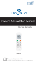
The modular Ethernet bridge IDU is implemented as 19” rack mountable aluminium
1U high unit; the depth of the unit is 230 mm without front panel handles and 270
mm with handles.
A maximum of 350 mm deep rack is required for the IDU to be mounted, from
mounting points of front panel, including space behind the unit for cables to RF,
Grounding point, Ethernet and Serial management interfaces. Some space is
required in front of the IDU for traffic interface cables, roughly 10 cm are needed for
V.35 interface port connector, 8 cm for E1 BNC port connectors.
The CFM-34-REBM IDU contains:
- Multiplexer board;
- Ethernet bridge board (provides the primary 100Base-Tx Ethernet interface);
- Interface module(s) (optional)
- Management controller board;
- IDU-ODU Cable interface;
- Baseband modem;
- Power Supply module;
- LCD and Keypad modules.
All the aforementioned boards and modules are interconnected with flat ribbon
cables and snap-on connectors.
Figure 1. Modular Ethernet bridge front panel (with no modules installed)
8 cm
10 cm
V.35 E1
4 cm
23 cm
(9.10 ")
(3.15 ")
(3.94 ")
(1.57 ")
(16.93 ")42.6 cm
(19.29 ")48.6 cm
12 cm
(4.72 ")
Eth
LAN
100M
CLEAR
ENTER
SL
RA
CFM-8-REBM
Slot 3 Slot 4

Modular Fast Ethernet Bridge Management System Technical Description and Configuration Guide
V. 3.12. 1.0 · © SAF Tehnika A/S 2003
5
The CFM-34-REBM IDU provides:
- Interfaces to:
- Radio outdoor Unit (ODU), N-type female connector;
- 100Base-Tx Ethernet LAN port, for connection to LANs;
- RS-232 serial management port;
- 10Base-T Ethernet management port;
- LCD display and corresponding keypad buttons to control LCD;
- LAN activity LEDs (speed, link integrity);
- Power connector;
- Reset button;
- DIP switch for the primary bridge configuration.
Table 1. Connectors
Front panel connectors
Connector or label Description
+-48V Power connector, IDU should be powered from 20 to 60 VDC
power source. Both “+” or “–“ poles of the power source could be
grounded, one should make sure if the chosen grounding wire is
connected to ground on the IDU power connector.
LAN 100Base-Tx Ethernet port (primary), shielded RJ-45 connector;
Interface module port
connectors
Please refer to Chapter 3.
Rear panel connectors
Connector or label Description
RF (N-type
connector)
Radio Unit port; Use 50 Ω coaxial cable with N-type male
connectors on both sides to connect the ODU to the IDU, such as
RG-213, LMR-400 or equivalent;
DB-9 RS232 management port for connection of ASCII console (or
analog line modem for the remote connection of ASCII console);
the RS232 console port is also used to update management
software.
RJ-45 10Base-T Ethernet management port, this port is used to connect
Telnet or Web terminal.
DB-25 Alarm port. This feature is optional.

Modular Fast Ethernet Bridge Management System Technical Description and Configuration Guide
V. 3.12. 1.0 · © SAF Tehnika A/S 2003 6
Table 2. Front panel LEDs
Label Color Description
RA Red Radio Alarm LED indicates problems with radio unit.
The following problems cause the Radio Alarm to turn on:
− Rx signal level is lower the predefined value, - the
corresponding parameter is RxAlarmLev on the LCD or
RxAlarmLevel using Telnet/ASCII console. The default value
for this parameter is -77 dBm;
− The humidity within the radio is too high (possibly ODU is
opened);
− Transmitter malfunction (TxOut=Error)
− RF Cable=Short – cable is faulty, RF Cable=Off – cable or
Radio is faulty;
− Tx and Rx syntheser loops are not locked (TxPLL=Error,
RxPLL=Error)
If not lit – operating properly (Rx=OK & TxOut=OK &
Humidity=Low & RF Cable – OK & TxPLL=OK & RxPLL=OK);
The RA LED will also switch on if the Radio loopback is active
and/or if the transmitter power is switched off.
The RA LED is updated one time per second.
SL Red Red Sync Lost LED indicates the multiplexer has lost
synchronization;
If not lit – operating properly;
The SL LED is updated one time per second.
100M Green Indicates LAN port speed: ON – 100 Mbps, OFF – 10 Mbps
Green
(right)
Indicates good LAN link integrity LAN port
connector
LEDs
Yellow
(left)
LAN receiving data

Modular Fast Ethernet Bridge Management System Technical Description and Configuration Guide
V. 3.12. 1.0 · © SAF Tehnika A/S 2003
7
Table 3. Rear side LEDs
The rear side LEDs refer to the operation of Ethernet port on the management
module board.
LED Description
A If blinking (with a period of about 1 sec.), indicates operation of the
management module CPU;
B If lit, indicates that Ethernet link is established with the
management terminal;
C If blinking, indicates data interchange between the IDU and the
management terminal;
Note: A, B and C correspondence to LEDs is shown in the figure below.
Figure 2. CFM-34 Remote Fast Ethernet Bridge rear side panel LEDs
For more information on Reset button please refer to the section 4.2.3.
2.1 Labelling
The IDU label is found at the rear panel;
P/N – product number, the last two numbers denote the product version;
S/N – serial number.
The combination of product number and serial number uniquely identifies each unit.
Figure 3. Label of the CFM-34-REBM IDU
AB C
Hidden reset
button

Modular Fast Ethernet Bridge Management System Technical Description and Configuration Guide
V. 3.12. 1.0 · © SAF Tehnika A/S 2003 8
3 Interface modules
3.1 V.35 Interface Module
V.35 interface module is provided with M34 standard connector. In the modular
Ethernet bridge the V.35 module terminates 2 Mbps from Mux and provides user
selectable data rates of 64 kbps, 128 kbps, 256 kbps, 512 kbps, 1024 kbps and
2048 kbps to single V.35 interface on M.34 connector.
3.1.1 Configuring V.35 Module
The V.35 interface module has three jumpers on the board. These jumpers are used
for adjusting the capacity.
V.35 vers. 2
jumpers for
configuration
of capacity ABC
V.35 interface module
The adjustments should be done in accordance with the table below.
The capacity can also be adjusted from IDU LCD or through the Telnet or ASCII
management terminal:
• From Telnet/ASCII terminal use the command line: “Mod # setv35 speed <speed
in kbps>”, see also Chapter 4.4.3 for details.
• From IDU LCD: Press “ENTER” to enter setup mode → select “Modules” → select
“Module # V35” → select “V.35 Speed” → “Change Speed”, choose the capacity
and confirm as prompted.
The special installation and configuration guide is available for V.35 Interface
module, which has a review of parameters and describes how to configure them, see
Refer for details.
Jumper
layout
A B C
Capacity,
[kbps]
2048
1024
512
256
128
64
Notes:
• A, B and C jumpers are depicted in the figure
above (on the right);
• - conjuncted jumper;
• For rates under 2 Mbps, the corresponding
multiplexer slot should be configured on 2 Mbps;
• * - Can be set from Telnet or ASCII console only;
• The software setting has a priority over the
jumper setting, i.e. if the software settings were
made, jumper setting is overrided.

Modular Fast Ethernet Bridge Management System Technical Description and Configuration Guide
V. 3.12. 1.0 · © SAF Tehnika A/S 2003 9
3.1.2 V.35 Interface Module LEDs
There are four LEDs on V.35 module. LEDs have a multifunctional meaning, basic
meanings are:
• C (DCD) - data carrier detected
• D (Data, both TxD and RxD)
• S (Send, both RTS - Request to Send, CTS - Clear to Send)
• R (Ready, both DSR - Data Set Ready, DTR - Data Terminal Ready)
General color meaning:
Green – normal operation; Yellow – information for service modes;
Red – fault indication; Not lit – no signal; Flickering – additional information.
Table 4. V.35 interface module LEDs
LED Description
Green – carrier is detected;
Red – carrier is NOT detected, (problem with radio)
C (DCD)
The following will be available through management facilities:
Flickering yellow and green(7:1) – loopback is set and carrier is
detected;
Flickering yellow and red(7:1) – loopback is set and carrier is NOT
detected;
Flickering yellow (7:1) – loopback is set and cable is damaged;
Flickering green (7:1) – cable is damaged and loopback is NOT set;
D (RxD,
TxD)
Green – both received and transmitted data signals are OK,
Off – none is present,
Green is blinking and goes off – just one data signal is present
(TxD:RxD = 7:1),
Yellow – remote loopback is set;
S (RTS,
CTS)
Green – both signals are active,
Off – both signals are inactive,
Flickering green – one control signal is present, another is absent
(RTS:CTS = 7:1),
Blinks yellow and red – module has set the CTS signal but the
returned signal is dissimilar to that set by the module, - indicates cable
fault;
R (DSR,
DTR)
Green – both signals are active,
Off – both signals are inactive,
Flickering green – one control signal is present, another is absent
(DSR:DTR = 7:1),
Blinks yellow and red – module has set the DSR signal but the
returned signal is dissimilar to that set by the module, - indicates cable
fault.

Modular Fast Ethernet Bridge Management System Technical Description and Configuration Guide
V. 3.12. 1.0 · © SAF Tehnika A/S 2003 10
3.2 E1 Interface Module
The E1 interface module is a single port module provided with two types of
interfaces:
• 120 Ω balanced interface, accessible through RJ-45 type connector,
• 75 Ω unbalanced interface, requires a pair of coaxial cables with the BNC type
connector.
Both interfaces are provided for termination of 2 Mbps (G.703) streams.
Table 5. E1 Interface module connectors
Out,
In
Two BNC connectors provide means to connect the CPE equipment to the IDU;
Tx data stream is transmitted over OUT (output) port;
Rx data is to be received through IN (input) port.
RJ-45 RJ-45 connector for balanced E1 interface.
Table 6. E1 interface module LEDs
Label Color Description
Tx Green Steady green light indicates the E1 module is ready to transmit data
to CPE connected to E1 port.
In case if Multiplexer synchronization is lost (S.L. LED is lit), Tx LED
goes off and AIS signal is transmitted from E1 port to CPE.
Rx Green Steady green light indicates the data signal from E1 input.
AIS Red Steady red LED indicates the AIS signal from E1 input.
LB Red “LoopBack” LED (red) indicates loopback mode is activated in the
module.
3.2.1 Configuring E1 Interface Module
The switching between balanced/unbalanced interfaces is available from
LCD/Keypad, Telnet, ASCII and Web terminals:
• From Telnet or ASCII console it can be accomplished using “Mod # setE1
{120|75}” command line, see Chapter 4.4.3.
• From IDU LCD: Press “ENTER” to enter setup mode → select “Modules” → select
“Module # E1” → select “E1 Interface” → “Ch. Interface”, choose the interface
and confirm as prompted.

Modular Fast Ethernet Bridge Management System Technical Description and Configuration Guide
V. 3.12. 1.0 · © SAF Tehnika A/S 2003 11
3.3 REB Interface Module
The CFM series REB interface module features a complete filtering Ethernet bridge.
The REB module terminates any capacity of 2-4-6-8 Mbps from the multiplexer on a
single 10 Mbps 10Base-T UTP Ethernet port.
REB Interface Module LEDs
There are two groups of LEDs on the front of the module:
• LAN: Rx, Tx
• WAN: Rx, Tx
Green color of the LED indicates activity.
Red color of the LAN Tx LED indicates the absence of the LAN link signal on the
Ethernet.
Red color of the LAN Rx LED indicates LAN collision in case if Ethernet port of the
REB module operates in Half Duplex mode.
The REB module has a connector and a jumper onboard marked with “JMP” and the
reset button to restart the Ethernet bridge.
JMP
Jumper and Connector
for production use only
(not configurable)
Reset button
Figure 3.1. The remote Ethernet bridge module
The reset button may useful for testing purposes.
Both the jumper and the connector are used for production and are not configurable.
The switching between Fdx and Hdx port modes can be accomplished as follows:
• From Telnet or ASCII terminal it can be accomplished using “Mod # setbridge
{Hdx|Fdx}” command line (Chapter 4.4.3).
• From IDU LCD: Press “ENTER” to enter setup mode → select “Modules” → select
“Module # Bridge” → select “Bridge Interface” → “Change FDX/HDX”, choose the
mode and confirm as prompted
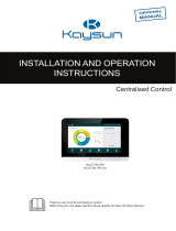
The front view of the interface modules: E1, REB, V.35
TX
AIS
LB
RX
E1
REB
LAN
RX
WAN
RX
TX TX
V.35
CDSR
OUT IN

Modular Fast Ethernet Bridge Management System Technical Description and Configuration Guide
V. 3.12. 1.0 · © SAF Tehnika A/S 2003 12
4 Management Interfaces
4.1 Reading the LEDs
Refer to Chapter 2 (Table 2) and Chapter 3.
4.2 LCD/Keypad
LCD display and keypad provides most basic method to locally configure and monitor
the local CFM terminal (IDU + ODU).
The LCD is constantly backlit and is able to display 2 lines of 16 symbols each line.
The LCD operates in two modes, Status display and Setup mode, please refer to
Flow Chart 1, page 43.
Keypad consists of 4 buttons:
ENTER is used to confirm the choice of displayed item or entered data as
well as to switch from status display to setup mode.
CLEAR is used to cancel the choice or to move to previous menu level.
↑ ↓ Up/Down buttons are used:
- To switch between options for menu items displayed;
- To choose parameter to set up and to set its value.
4.2.1 “Status Display” Mode of the IDU LCD Management Interface
Once the IDU is powered up, it automatically enters “Status Display” mode,
displaying two parameters at a time statically (use up/down buttons to scroll through
parameters). These parameters are listed in the Table 7.
Table 7
Parameter Values and description
Tx=23362.5MHz Parameter indicates Tx frequency of the Radio.
Rx=22354.5MHz Parameter indicates Rx frequency of the Radio.
TxPower=+20dBm Parameter indicates Tx power of the Radio.
Rx= OK Rx parameter indicates various states of IDU receiver and ODU:
“OK” indicates the IDU receives acceptable signal from ODU;
“Low” indicates the received signal level is too low for the IDU to
operate properly;
“Error” indicates some internal fault in the ODU receiver, please
contact sales representative or manufacturer.
Cable=–5 dB Parameter indicates signal attenuation in ODU-IDU cable, values
of 0 … -20 dB provide proper operation of IDU.

Modular Fast Ethernet Bridge Management System Technical Description and Configuration Guide
V. 3.12. 1.0 · © SAF Tehnika A/S 2003 13
RxLev= -66dBm Parameter RxLev indicates the level of the received signal,
values from –40 dBm to –90 dBm provide proper operation of
the system.
TxOut=Ok Parameter indicates operation status of ODU transmitter:
“Ok” indicates proper operation;
“Error” indicates internal fault in ODU transmitter, please
contact sales representative or manufacturer.
TxPLL=Ok Parameter indicates operation status of ODU Tx Syntheser Loop
(PLL lock):
“Ok” indicates proper operation;
“Error” indicates internal fault in ODU transmitter, please
contact sales representative or manufacturer.
RxPLL=Ok Parameter indicates operation status of ODU Rx Syntheser Loop
(PLL lock):
“Ok” indicates proper operation;
“Error” indicates internal fault in ODU receiver, please contact
sales representative or manufacturer.
t= 23C Indicates ODU internal temperature
Humidity=Low Parameter indicates humidity level inside ODU,
“Low” indicates acceptable moisture levels;
“High” indicates too high level of humidity, condensing.
Restart= 3 Parameter indicates number of ODU management controller
restarts since counter was reset.
IDU t= 31C Parameter indicates internal temperature inside IDU
LAN= Half Duplex Parameter indicates the primary Ethernet port mode: "Eth=Half
Duplex" or "Eth= Full Duplex".
LAN link= OFF Indicates Ethernet LAN link integrity
LAN speed= 10M Indicates the primary Ethernet port speed: 10M or 100M
RF Cable – OFF Parameter indicates power consumption of the ODU:
“OK” indicates acceptable level;
“Short” indicates short circuit in cable;
“Off” indicates too low power consumption by ODU. This is most
likely due to the brake in the cable. If the cable is intact, the
ODU is faulty (contact your SAF Tehnika sales representative).
MUX
0M+34M+0M+0M
Indicates the current MUX slot speed configuration (see chapter
4.2.2 for details).
RxAlarmLev =-71 Indicates the Rx level (in dBm) at which the Radio Alarm is
switched on (parameter adjustable from Telnet/ASCII console).
UpTime=5371 Indicates the system up-time in seconds.
DownTime=4 Indicates the system down-time (SL alarm on) in seconds.
FrmErr=23 Indicates the count of frames received from the WAN that has
error(s) within the time interval equal to the sum of uptime and
downtime counters.
BBLoopback=OFF Indicates if the base-band loopback is switched on or off.

Modular Fast Ethernet Bridge Management System Technical Description and Configuration Guide
V. 3.12. 1.0 · © SAF Tehnika A/S 2003 14
4.2.2 “Setup” Mode of the IDU LCD Management Interface
Following table describes parameters available for change by the CFM-34-REBM
Indoor Unit in “Setup” mode.
Algorithm of LCD operation is shown on Flow Chart 1, page 43.
Table 8
Parameter Values and description
Change Chan ## “Change Chan” item provides ODU Tx and Rx frequency setup
functionality:
If this item is chosen LCD shows, for example:
where “163” – number of currently used Tx channel and “Tx” -
frequency appropriate to channel.
Channel numbers and corresponding Tx, Rx frequency values are
listed in tables in Chapter 8, page 52.
Operator sets desired channel number scrolling through values with
“Up” or “Down” buttons and confirming the choice with “Enter” button.
Tx Power +5dBm “TxPower” parameter sets the ODU Transmitter power rate.
The default setting is “OFF”, allowing safe deployment of the
equipment avoiding interference risk with other radio equipment.
Select IP Default value - 192.168.205.010 or 192.168.206.010
Important!: Do not enter address “255.255.255.255”
Select NETMASK Default value – 255.255.255.000
Select Gateway Default value – 255.255.255.255 (No gateway specified)
IP (IP address), Netmask and Gateway parameters provide the
means of addressing management board of IDU in order to control
and manage IDU locally and monitor ODU both locally and remotely.
Note: It is necessary to restart the management CPU for any changes
in IP settings (including SNMP terminal IP settings) to take effect.
Access Code Specify the panel access code (a number from 0 – 200) to enable any
adjustments from IDU.
Reset counters Resets up-time, down-time and Frame error counter, see page 30 for
details.
RF loopback OFF Turns the RF loopback (Radio loopback) on or off.
BB loopback ON Turns the baseband loopback on/off (BB loop analog – analog base-
band loop, BB loopback on – digital base-band loopback).
MUX speeds Sets the data rate for multiplexer slots (for slot numbering see Figure
1); the following configurations are available:
Data rate
Designation Primary Ethernet Slot 3 Slot 4
0M+34M+0M+0M 34 Mbps 0 Mbps 0 Mbps
0M+30M+2M+2M 30 Mbps 2 Mbps 2 Mbps
0M+32M+0M+2M 32 Mbps 0 Mbps 2 Mbps
0M+32M+2M+0M 32 Mbps 2 Mbps 0 Mbps
The numbering of slots is shown in Chapter 2.
Note: if no additional interface modules are used, the multiplexer
should be configured as [0M+34M+0M+0M] to ensure maximum
capacity (34 Mbps) of the primary Ethernet interface.
continued on next page

Modular Fast Ethernet Bridge Management System Technical Description and Configuration Guide
V. 3.12. 1.0 · © SAF Tehnika A/S 2003 1
5
continued from previous page
Setup mode menu tree
Access code Change * - current channel number
Restart CPU ** - multiplexer slot number
Reset Counters *** - Dloop - Digital loopback
Write Config **** - Aloop - Analog loopback
Loopbacks RF loopback ON
RF loopback OFF
BB loopback ON
BB loop analog
BB loopback OFF
Outdoor unit Chan ##* Change Chan ##
Power Tx Power
Ethernet Select IP Change
Select NETMASK Change
Select Gateway Change
Modules Module #** Bridge Bridge interface Change FDX/HDX
Module # E1 E1 Interface Ch. Interface
E1 Dloop*** Change Dloop
E1 Aloop**** Change Aloop
Module # V35 V.35 Speed Change Speed
V.35 Loopback Change Loopback
V.35 Clock Change Mode
Module # N/A
MUX Speeds Change
Service line Select local IP Change
Select remote IP Change
4.2.3 Reset Functions
Depending on the method used, the user may reset the whole terminal (IDU+ODU)
or the management controller individually, see table below for details.
Reset through the LCD menu
system using “Restart CPU”
option or from the
Telnet/ASCII console using
“restartcpu” command
Restarts the management module. Resets all
management counters.
Reset action using hidden
button at the rear side of the
IDU (see Figure 2)
Restarts both the multiplexer module and the
management module. Resets all management
counters.
Note: This may require a pin, at least 15 mm long,
approx. 1.5 mm in diameter.
Unplugging of power supply Restarts the multiplexer module and the management
module. Resets all management counters.
Write config Saves all settings in EPROM of the management controller.
Restart CPU Restarts management CPU for the new IP settings to take effect.
Resets all management counters.

Modular Fast Ethernet Bridge Management System Technical Description and Configuration Guide
V. 3.12. 1.0 · © SAF Tehnika A/S 2003 16
4.3 RS-232 Serial Management Port
RS-232 serial management port of the IDU will provide terminal management via
connected PC or other terminal or modem.
In order to interconnect the IDU and the management terminal directly through
serial ports, a straight through modem cable is needed. The serial port of the
management terminal should be configured as 19200 8-N-1, no data flow control.
Modem PC/Terminal
Modem
IDU
PC/Terminal
IDU RS-232
RS-232
If using modems, the management terminal is connected with the IDU remotely
through a telephone line. In this case the modem, which is connected with the IDU,
should be configured as stated below:
- Auto answer on first ring ON
- Echo offline commands OFF
- Suppress result codes
- DTR override
The modem configuration then should be saved (typically with AT&W string).
Telnet/ASCII management console command interface
For the pin assignments of the RS232 serial port, please refer to the CFM-LM series
product family technical description. The document can be ordered from SAF Tehnika
sales representatives or downloaded from SAF Tehnika’s Web site (see Chapter 8).

Modular Fast Ethernet Bridge Management System Technical Description and Configuration Guide
V. 3.12. 1.0 · © SAF Tehnika A/S 2003 1
7
In order to connect the PC to the RS232 management port using Hyper Terminal
program (this program is included in any Windows version), proceed as described
below.
1. Connect PC to the RS232 serial port by means of “straight through” or modem
serial cable (null-cable).
2. Run “Hyper Terminal” program.
3. Make a New connection, enter connection name.
4. Choose port (COM1 or COM2).

Modular Fast Ethernet Bridge Management System Technical Description and Configuration Guide
V. 3.12. 1.0 · © SAF Tehnika A/S 2003 18
5. Set port settings (bits per second: 19200, data bits: 8, parity: none, stop bits: 1,
no data flow control).
6. Press OK
7. Press Enter. Password is disabled by default.
If successfully connected, the prompt should appear as in the picture below; see
Chapter 4.4.3 for available commands.

Modular Fast Ethernet Bridge Management System Technical Description and Configuration Guide
V. 3.12. 1.0 · © SAF Tehnika A/S 2003 19
4.4 Ethernet Management Port
Ethernet port of the CFM-34-REBM IDU terminal is intended as main source of
management connectivity and will provide the broadest range of management
functionality:
- Web management via integrated Web server of management board;
- SNMP management via integrated SNMP agent of management board;
- Telnet server and CLI interface.
Ethernet interface could be used:
- To connect IDU to PC/Laptop to manage IDU;
- To LAN for constant monitoring of IDU;
- To router or any other TCP/IP packet network termination unit to have IDU as
part of network for management information.
4.4.1 Web Interface
The implementation of Web interface for the CFM-34-REBM IDU provides monitoring
and configuration capabilities similar to ones available from the IDU LCD/Keypad,
front panel LEDs, and from the Telnet/ASCII console, for details please refer to
Chapters 4.2.1, 4.2.2, and 4.4.3.
The Web interface functionality is available via the Ethernet management
port only.
Web interface is accessible by any standards based Web browser.
The CFM-34-REBM IDU Main Web management window: it shows the Radio
characteristics, main system settings, and alarm status. Entries, which are
highlighted in red, indicate that specific parameters do not comply with the norms of
normal operation, all other parameters are satisfactory

Modular Fast Ethernet Bridge Management System Technical Description and Configuration Guide
V. 3.12. 1.0 · © SAF Tehnika A/S 2003 20
To check the status of each module, click on a Module Status link to open the
module status window.
The CFM-34-REBM Module Status window
When clicked on the link of any of the configuration windows for the first time since
the main Web page was opened, you will be prompted to enter User Name and
Password. The default username is SAF (in capital letters) and the default password
is test.
There are two configuration windows, - the Main Configuration window and the
Module Configuration window.
The following operations can be performed from the Main Configuration window:
− restart the system,
− save the current configuration,
− change MUX slot speeds,
− change the Web page refresh time.
Page is loading ...
Page is loading ...
Page is loading ...
Page is loading ...
Page is loading ...
Page is loading ...
Page is loading ...
Page is loading ...
Page is loading ...
Page is loading ...
Page is loading ...
Page is loading ...
Page is loading ...
Page is loading ...
Page is loading ...
Page is loading ...
Page is loading ...
Page is loading ...
Page is loading ...
Page is loading ...
Page is loading ...
Page is loading ...
Page is loading ...
Page is loading ...
Page is loading ...
Page is loading ...
Page is loading ...
Page is loading ...
Page is loading ...
Page is loading ...
Page is loading ...
Page is loading ...
Page is loading ...
Page is loading ...
Page is loading ...
/