ST VL53L1X API User manual

Type
User manual

ST VL53L1X API is a comprehensive software package that unleashes the capabilities of your ST VL53L1X long-distance ranging Time-of-Flight sensor. With this API, you can effortlessly measure distances with high accuracy and precision, making it ideal for various applications such as people counting, robotics, and industrial automation.

ST VL53L1X API is a comprehensive software package that unleashes the capabilities of your ST VL53L1X long-distance ranging Time-of-Flight sensor. With this API, you can effortlessly measure distances with high accuracy and precision, making it ideal for various applications such as people counting, robotics, and industrial automation.

Introduction
This user manual explains how to use a VL53L1X long-distance ranging Time-of-Flight (ToF) sensor to count people crossing a
specific predefined area, like a meeting room entrance or a particular location in a corridor. It also describes an algorithm used
to count the people. The algorithm is provided as an example and can be downloaded from st.com, in the VL53L1X embedded
SW section, under the reference STSW-IMG010.
In addition, this document presents the details of a counting application where a sensor is set on the top, not the side, of the
area to be tracked.
Counting people with the VL53L1X long-distance ranging Time-of-Flight sensor
UM2600
User manual
UM2600 - Rev 1 - June 2019
For further information contact your local STMicroelectronics sales office.
www.st.com
1Acronyms and abbreviations
Table 1. Acronyms and abbreviations
Acronym/abbreviation Definition
FoV field of view
SPAD single photon avalanche diode
SW software
ToF Time-of-Flight
UM2600
Acronyms and abbreviations
UM2600 - Rev 1 page 2/14
2Overview
Counting people with the VL53L1X consists of using the multiple zones of the sensor receiving SPAD area, and of
configuring it with two distinct fields of view (FoV), to alternatively get a ranging distance from them and
consequently recognize the movements of a person. Using this method, the number of people occupying a
meeting room, accessible from a reasonably narrow access, is known at all times by detecting the entrances and
exits of the attendees.
By measuring and analyzing the distances of targets within the FoVs of a front and back zone (see figure below
and Figure 3. Front and back zones), a simple algorithm can detect the direction a person crosses the area under
the two FoVs. This algorithm "understands" that someone is under one of the FoV as long as the distance
measured by the sensor under this FoV is between 0 and a threshold value specified in mm.
Figure 1. VL53L1X FoV divided in two subfields of view
From a timing perspective, the sensor alternatively ranges on each of the two zones, for a very short period of
time in milliseconds. It is possible to determine in which direction a person crosses the area, depending in which
order this person has been detected in the two zones, as shown in the figure below.
Figure 2. Person counting chronogram
UM2600
Overview
UM2600 - Rev 1 page 3/14
3Algorithm description
The counting algorithm example relies on a list of states that have to occur in a certain order to detect if a person
has crossed the specified area and in which direction this area has been crossed. These states are stored in a list
and compared to two default lists of states that represent how the area is crossed in two different directions.
When no-one is seen in either of the two zones, the list of states is reset.
If we consider that a person detected in the front zone equals 2, and a person detected in the back zone equals 1,
the algorithm adds the value of the two states and stores the result as soon as it changes.
Eventually, if the consecutive states in the list are 0, 1, 3, 2, 0 or 0, 2, 3, 1, 0 this means a person has been
detected in one direction or the other, as described in the figures below.
Figure 3. Front and back zones
Figure 4. List of status vales
UM2600
Algorithm description
UM2600 - Rev 1 page 4/14
4Hysteresis
The algorithm validates a crossing event only when a person has fully crossed the two zones. It does not validate
the event when the person remains for a long time under the FoV or when the person decides to return from the
place he came from.
This is illustrated in the figure below: the algorithm stops and the list of states is reset as soon as no-one is
detected in any of the two FoVs.
Figure 5. Hysteresis principle
UM2600
Hysteresis
UM2600 - Rev 1 page 5/14
5VL53L1X sensor and algorithm configuration
It is sufficient to set the two FoVs by dividing the 16*16 SPAD array of the VL53L1X sensor into two sub N*16
arrays. For example, N can be chosen within the interval [4, 8]. This means that it is not necessary to use the
same SPADs for front and back ranging. Alternatively, enabling 7*16 SPADs is sufficient to see a person in the
two zones at the same time when this person stands directly under the sensor, in the middle of the two FoVs.
Figure 6. Example of configuration of the SPAD array
UM2600
VL53L1X sensor and algorithm configuration
UM2600 - Rev 1 page 6/14
6Software and board package
The software code example runs a proof of concept, implementing the algorithm as described in the sections
above. This software runs on a NUCLEO F401RE board and is accompanied by one X-NUCLEO 53L1A1
expansion board. The VL53L1X “left” satellite (see figure below) is the one enabled by the software example.
Figure 7. NUCLEO F401RE, X-NUCLEO, and VL53L1X satellite sensors
To test the software, you can move your hand from right to left or from left to right, at a distance of around 30 cm
above the sensor at a reasonable speed. Moving your hand simulates a person crossing a specified area which
gives an output on a counter.
The serial speed is set at the 460800 bauds per second.
The figure below shows the captured distances from two zones, where the VL53L1X is set at 2600 mm from the
floor. The black arrows correspond to the times when a person was detected entering or exiting the area being
tracked. Three crossings are visible. The first two arrows correspond to two entries and the last one corresponds
to an exit. The red and blue dots are distances measured by the sensor from the front and back zones.
UM2600
Software and board package
UM2600 - Rev 1 page 7/14
Figure 8. Example of captured distances
UM2600
Software and board package
UM2600 - Rev 1 page 8/14
7Setup reliability
7.1 Ranging on the floor
Reliability of the algorithm relies on the accuracy of the setup which detects the distance between the sensor and
the floor. This can be ensured only if nothing (e.g. no obstacle or static object) blocks the front and back FoVs.
The two figures below illustrate two cases where the distance to the floor is measured over many measurements.
The mean of the measured distances (if they equal the real distance between the sensor and the floor) and the
standard deviation, are an indication of the reliability of the setup.
It is recommended to consider a minimum distance of 700 mm between the floor and the sensor threshold as this
validates a person crossing the FoV under the sensor. This 700 mm is a good estimate of the maximum standard
deviation that we can consider in a noisy environment to define if a setup is reliable or not (see the real test
examples in the following figures).
In Figure 9. Reliable setup, the mean of the measured distances from the two zones is the same and the
minimum measured distance is less than the distance between the sensor and the floor (2600 mm) minus 700
mm. This indicates a reliable setup.
Figure 9. Reliable setup
UM2600
Setup reliability
UM2600 - Rev 1 page 9/14
In Figure 10. Unreliable setup, the mean of the measured distances from the two zones is significantly different
and the minimum measured distance is greater than the distance between the sensor and the floor (2600 mm)
minus 700 mm. This indicates an unreliable setup.
Figure 10. Unreliable setup
The "reliable" setup is considered good because the sensor detects only the floor in the two FoVs. Consequently,
the verticality of the FoV is ensured. However, the tracking area must not be too narrow. In situations where the
verticality cannot be fully ensured, or when the FoVs are narrow, it is advised to alternatively enable N*M SPADs
as follows:
N to be within the interval [4, 8] as described above and enabled SPADs should be centered
M to be within the interval [8, 16] and the SPADs to remain centered for a narrow but non vertical setup. If
the verticality of the FoV cannot be ensured, the SPADs do not have to be centered.
Floor detection reliability can be checked by running a trimming procedure to adjust the width of the back and
front FoVs, by enabling the relevant SPADs. Analysis of the extracted histograms can help in detecting the SPADs
belonging to the parts of the FoVs that do not range on the floor and should never be enabled. Note that the
smaller the number of lines of SPADs used for this trimming, the larger the number of histogram values that have
to be computed.
UM2600
Ranging on the floor
UM2600 - Rev 1 page 10/14
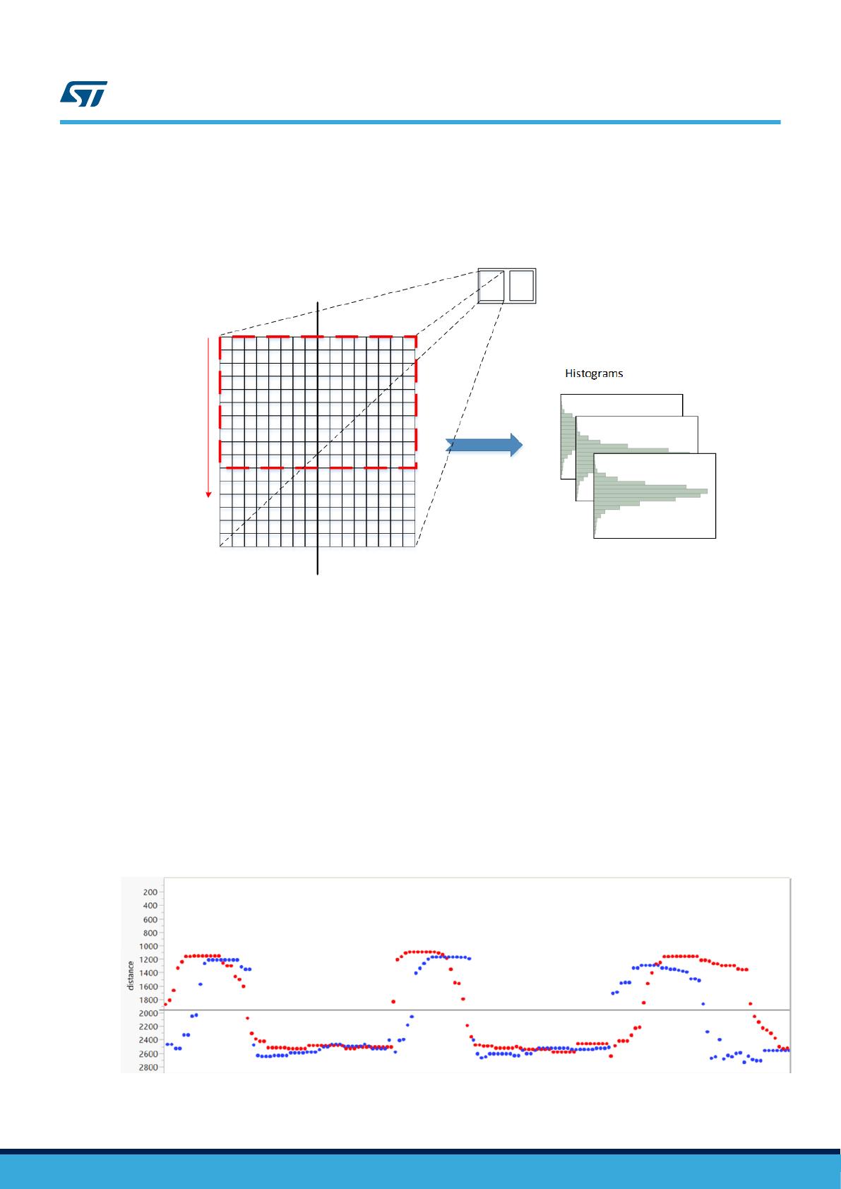
The figure below shows a trimming procedure example in which a significant number of distances have been
extracted by ranging with the SPADs enabled within the red rectangle (10 SPADs lines). The red rectangle can be
moved by one line or more between each test.
Figure 11. Trimming procedure
7.2 Ensure overlap in the two detection zones
The algorithm example relies on the fact that a person crossing an area being tracked must first be detected in
the first zone, then in both zones at the same time, and finally in the second zone. In Figure 8. Example of
captured distances, both tracking paths have a few dots corresponding to the moment when a person was
detected in both zones simultaneously. Increasing N, increases this number of dots, but could decrease the
number of dots corresponding to the time when a person is detected only in the first or second zone.
To optimize the behavior of the algorithm, it is advised to choose N as small as possible and to apply a filter, on
the detected distances, which consists of considering only the minimum distance value from the last Z
measurements, up to the time where a person is detected in the last zone. This significantly optimizes the
probability of detecting a person in each of the zones of the tracking path.
Note that this filter is not implemented in the source code example.
The figure below shows the well-defined detection of a person in each of the three zones.
Figure 12. Filter on the measured distances with Z = 10, N = 6, M = 16
UM2600
Ensure overlap in the two detection zones
UM2600 - Rev 1 page 11/14
Revision history
Table 2. Document revision history
Date Version Changes
26-Jun-2019 1 Initial release
UM2600
UM2600 - Rev 1 page 12/14
Contents
1Acronyms and abbreviations ......................................................2
2Overview ..........................................................................3
3Algorithm description..............................................................4
4Hysteresis .........................................................................5
5VL53L1X sensor and algorithm configuration ......................................6
6Software and board package.......................................................7
7Setup reliability....................................................................9
7.1 Ranging on the floor ............................................................9
7.2 Ensure overlap in the two detection zones ........................................11
Revision history .......................................................................12
Contents ..............................................................................13
UM2600
Contents
UM2600 - Rev 1 page 13/14
IMPORTANT NOTICE – PLEASE READ CAREFULLY
STMicroelectronics NV and its subsidiaries (“ST”) reserve the right to make changes, corrections, enhancements, modifications, and improvements to ST
products and/or to this document at any time without notice. Purchasers should obtain the latest relevant information on ST products before placing orders. ST
products are sold pursuant to ST’s terms and conditions of sale in place at the time of order acknowledgement.
Purchasers are solely responsible for the choice, selection, and use of ST products and ST assumes no liability for application assistance or the design of
Purchasers’ products.
No license, express or implied, to any intellectual property right is granted by ST herein.
Resale of ST products with provisions different from the information set forth herein shall void any warranty granted by ST for such product.
ST and the ST logo are trademarks of ST. For additional information about ST trademarks, please refer to www.st.com/trademarks. All other product or service
names are the property of their respective owners.
Information in this document supersedes and replaces information previously supplied in any prior versions of this document.
© 2019 STMicroelectronics – All rights reserved
UM2600
UM2600 - Rev 1 page 14/14
  • Page 1 1
  • Page 2 2
  • Page 3 3
  • Page 4 4
  • Page 5 5
  • Page 6 6
  • Page 7 7
  • Page 8 8
  • Page 9 9
  • Page 10 10
  • Page 11 11
  • Page 12 12
  • Page 13 13
  • Page 14 14

ST VL53L1X API User manual

Type
User manual

ST VL53L1X API is a comprehensive software package that unleashes the capabilities of your ST VL53L1X long-distance ranging Time-of-Flight sensor. With this API, you can effortlessly measure distances with high accuracy and precision, making it ideal for various applications such as people counting, robotics, and industrial automation.

Ask a question and I''ll find the answer in the document

Finding information in a document is now easier with AI