Peavey UMA 35T II User manual
- Category
- Musical Equipment
- Type
- User manual

S P E C I F I C A T I O N S
Outputs:
Direct: 4 ohms
XFMR: 8 ohms, 600 ohms, 25 V, and
70 V (balanced)
Ch. 3 Output, Loop Out, AUX Out:
1 V @ 100 ohms
Inputs:
Channel 1:
Low-Z 500 uV @ 1.8 K ohms (XLR or
screw terminals)
High-Z 50 mV @ 9.5 K ohms
(screw terminals)
Channel 2:
Low-Z 500 uV @ 1.8 K ohms
(screw terminals)
High-Z 50 mV @ 9.5 K ohms (RCA or
screw terminals)
Channel 3:
High-Z 50 mV @ 9.5 K ohms (RCA)
Page: 100 mV (600 ohm transformer
balanced screw terminals)
Loop In: 1 volt @ 3.6 K ohms
Tone Controls:
Bass: ±10 dB @ 100 Hz
Treble: ±10 dB @ 10 kHz
Contour: +6 dB @ 100 Hz and 10 kHz
Controls:
Channel 1 Volume Control
Channel 2 Volume Control
Channel 3 Volume Control
Page 1 Volume Control (rear panel
screwdriver adjust)
Page Mute Threshold Control (rear
panel screwdriver adjust)
Channel 1 Mute Threshold Control
(rear panel screwdriver adjust)
Bass Control
Treble Control
Master Volume Control
Contour Switch
Link Switch
Power Switch
Indicators:
Power Indicator (Red LED)
Activity Indicator (Green LED)
SPS™ Active Indicator (Yellow LED)
Mute 1 and Mute 2 Indicators (Yellow
LEDs)
Muting:
Mute 1: Page input overrides
Channels 1 through 3 with
adjustable threshold
Mute 2: Channel 1 overrides Channels
2 and 3 with adjustable
threshold
Power Requirements:
120 V AC, 60 Hz
Other Features:
Remote Volume Control via screw
terminals
Mute 1 and Mute 2 switch closure via
screw terminals
15 V DC phantom power on Low-Z
inputs
FEATURES
• Two mic/line inputs with screw
terminals on each; one with XLR and
one with dual RCA phono jacks
• One line level input with dual RCA
phono jacks
• One dedicated 600 ohm transformer
balanced paging input with screw
SPECIFICATIONS
Output Power:
35 watts
Frequency Response:
Power Amplifier:
Direct: ±0.5 dB, 20 Hz to 20 kHz
XFMR: ±0.5 dB, 50 Hz to 20 kHz
Preamplifier:
±1.5 dB, 50 Hz to 20 kHz
Distortion:
Power Amplifier:
0.02% (1 kHz)
Preamplifier:
< 0.1% with nominal gain settings
S/N Ratio:
Master Volume Min:
95 dB below rated power
Master Volume Max:
80 dB below rated power
High-Z Inputs:
75 dB below rated power
Low-Z Inputs:
65 dB below rated power
Power Bandwidth:
Direct: 20 Hz to 20 kHz < 0.5% THD
XFMR: 50 Hz to 20 kHz < 0.5% THD
Output Regulation:
Direct: < 0.5 dB
XFMR: < 1.0 dB
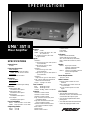
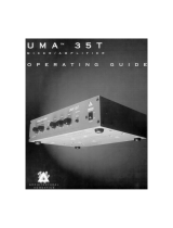
UMA
™
35T II
Mixer Amplifier
®
ARCHITECTURAL ACOUSTICS
®

terminals and rear panel screwdriver
adjust level control
• Two mute lines, providing internal
signal override or external switch
closure, with adjustable thresholds
and indicators
• Provisions for external master
volume control
• Bass, Treble, and Contour EQ
controls
• Loop Out/Loop In patch point with
RCA phono connectors and link
switch
• Channel 3 output (RCA phono),
which gives a non-mutable output of
Channel 3
• AUX output for tape recorders, etc.
• Signal activity indicator
• Power indicator
• SPS™ (Speaker Protection System)
circuitry with indicator
• 4 ohm, 8 ohm, 25 V and 70 V
transformer-isolated outputs
• 600 ohm balanced line level output
• AC convenience outlet
• Powder coated steel chassis
• Optional rack-mounting kits available
DESCRIPTION
The UMA™ 35T II is a versatile mixer/
amplifier designed for numerous sound
reinforcement applications. The flexible
input configurations make it an excel-
lent choice for paging and/or back/
foreground music systems. The UMA™
Series mixer/amplifiers are ready for
any job, utilizing an isolated transformer
with multiple output configurations.
ARCHITECTURAL &
ENGINEERING
SPECIFICATIONS
The mixer amplifier shall have two
microphone/line inputs, one line input,
and one dedicated page input. Channel
1 shall have screw terminals and an
XLR connector for the Low-Z input;
screw terminals for the Hi Z input.
Channel 2 shall have screw terminals
for the Low- Z input; screw terminals
and RCA phono connectors for the
High-Z inputs. Channel 3 shall have
RCA phono connectors. Channels 1
and 2 shall have 15 volt phantom power
for the Low-Z inputs. The page input
shall be transformer balanced
(600 ohms) and shall have screw
terminals for the input connection.
The master section shall include one
master volume level control, two EQ
controls providing 10 dB boost or cut at
100 Hz and 10 kHz, and a "Contour"
switch providing 6 dB of boost at
100 Hz and 10 kHz.
The unit shall have two levels of
automatic muting. Mute 1 shall give
LIMITED WARRANTY
Peavey Electronics Corporation warrants to the original purchaser of this new Architectural Acoustics product that it is free from
defects in material and workmanship. If within one (1) year from date of purchase a properly installed product proves to be defective and
Peavey is notified, Peavey will repair or replace it at no charge. (Note: Batteries and patch cords not covered.) “Original purchaser” means
the customer for whom the product is originally installed.
Damage resulting from improper installation, interconnection of a unit or system of another manufacturer, accident or unreasonable
use, neglect or any other cause not arising from defects in material and workmanship is not covered by this warranty. The warranty is
valid only as to products purchased and installed in the United States and Canada.
THIS LIMITED WARRANTY IS IN LIEU OF ANY AND ALL WARRANTIES, EXPRESSED OR IMPLIED, INCLUDING THE IMPLIED
WARRANTIES OF MERCHANTABILITY AND FITNESS FOR A PARTICULAR USE. UNDER NO CIRCUMSTANCES WILL PEAVEY BE
LIABLE FOR ANY LOST PROFITS, LOST SAVINGS, INCIDENTAL DAMAGES OR CONSEQUENTIAL DAMAGES ARISING OUT OF THE USE
OR INABILITY TO USE THE PRODUCT, EVEN IF PEAVEY HAS BEEN ADVISED OF THE POSSIBILITY OF SUCH DAMAGE. THIS LIMITED
WARRANTY IS THE ONLY EXPRESSED WARRANTY ON THIS PRODUCT, AND NO OTHER STATEMENT, REPRESENTATION, WAR-
RANTY, OR AGREEMENT BY ANY PERSON SHALL BE VALID OR BINDING UPON PEAVEY.
Peavey’s liability to the original purchaser for damages for any cause whatsoever and regardless of the form of action is limited to
the actual damages up to the greater of Five Hundred Dollars ($500) or an amount equal to the purchase price of the product that caused
the damage or that is the subject of or is directly related to the cause of action. This limitation of liability will not apply to claims for personal
injury or damage to real property or tangible personal property allegedly caused by Peavey’s negligence. For information on service
under this warranty, call a Peavey customer service representative at (601) 483-5376.
Features and specifications subject to change without notice.
A Division of Peavey Electronics Corporation
711 A Street / Meridian, MS 39301 / U.S.A. / (601) 483-5376 / Fax 486-1154
©1994 #80302293 Printed in U.S.A. 12/94
precedence to the page input, and it
shall override Channels 1 through 3,
with a threshold control on the page
input. Mute 2 shall give precedence to
Channel 1, and it shall override
Channels 2 and 3, with a threshold
control on Channel 1. The two mute
lines shall have screw terminals for
external mute control.
The unit shall have a Channel 3
output that provides an RCA phono,
non-mutable output of Channel 3.
Provision for an external master volume
control shall be made via screw
terminals.
The unit shall be packaged in a
rugged metal chassis 17" wide by
3-1/2" high by 15-5/8" deep. The unit
shall operate from standard 120 volts
AC, 60 Hz power. The internal power
amplifier shall be capable of delivering
35 watts into 4 ohms and 8 ohms, as
well as providing 25 volt and 70 volt
balanced line outputs. The unit shall be
capable of delivering rated power from
20 Hz to 20 kHz ±1.5 dB into 4 ohms at
its direct output at 0.5% or less distor-
tion with hum and noise at least 80 dB
below rated output from line level
inputs. The unit shall be called the
Peavey Architectural Acoustics Division
model UMA™35T II.
®
ARCHITECTURAL ACOUSTICS
®
TM
®
-
 1
1
-
 2
2


Peavey UMA 35T II User manual
- Category
- Musical Equipment
- Type
- User manual
Ask a question and I''ll find the answer in the document
Finding information in a document is now easier with AI
Related papers
-
Peavey UMA 75/150T II Owner's manual
-
-
-
 UMA Enterprises UMA/35T Utility Mixer/Amplifier User manual
-
-
-
-
-
-

